4.11 LCD1602 display screen
4.11.1 introduction to schematic diagram
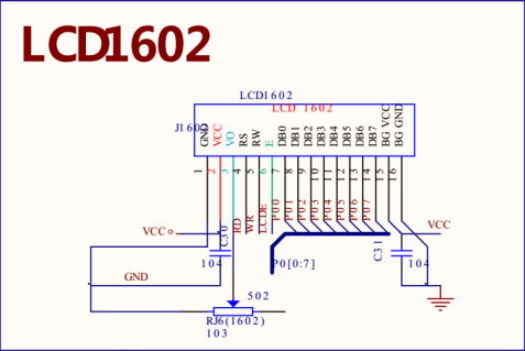
Figure 4-11-1
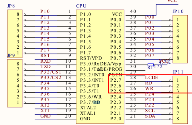
Figure 4-11-2
According to the schematic diagram:
The data pin of LCD1602 is connected to port P0.
RD(RS) pin is connected to P2 six
WR(RW) pin is connected to P2 five
LCDE(E) pin is connected to P2 seven
4.11.2 introduction to LCD1602 character screen
1602 LCD is also called 1602 character LCD. It is a dot matrix LCD module specially used to display letters, numbers and symbols.
It is composed of several 5x7 or 5x11 dot matrix character bits. Each dot matrix character bit can be used to display a character. There is an interval between each dot and between each line, which plays the role of character spacing and line spacing. Because of this, it can not display pictures well.
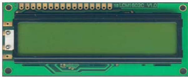
Figure 4-11-3
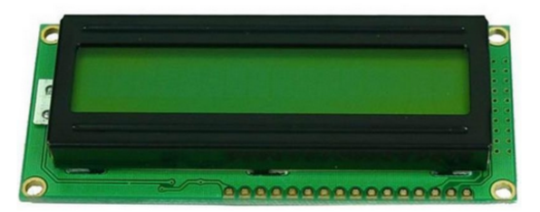
Figure 4-11-4

Figure 4-11-5
4.11.3 timing introduction
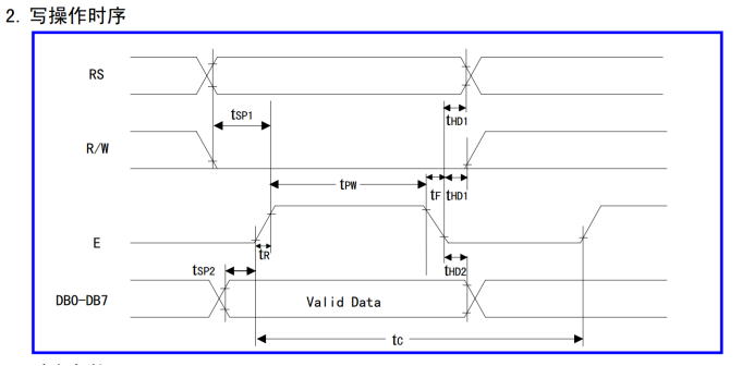
Figure 4-11-6
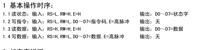
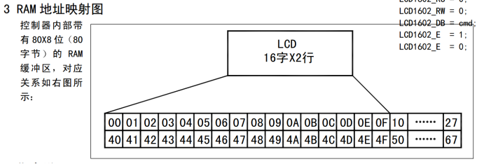
Figure 4-11-8
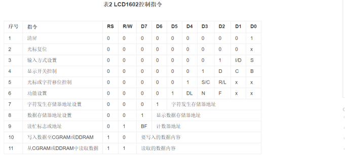
Figure 4-11-9
The read / write operation of LCD1602 LCD module and the operation of display screen and cursor are realized through instruction programming (where 1 is high level and 0 is low level), which are introduced as follows.
(1) Command 1: clear the screen. Instruction code 01H, the cursor is reset to address 00H.
(2) Instruction 2: cursor reset. Reset the cursor to address 00H.
(3) Instruction 3: input mode setting. Wherein, I/D represents the moving direction of the cursor, and the high level moves to the right and the low level moves to the left; S indicates whether all words on the display screen move left or right. High level indicates valid and low level indicates invalid.
(4) Command 4: display switch control. Among them, D is used to control the on and off of the overall display, high level indicates on display, and low level indicates off display; C is used to control the opening and closing of the cursor. A high level indicates that there is a cursor and a low level indicates that there is no cursor; B is used to control whether the cursor flashes, high level flashes and low level does not flash.
(5) Instruction 5: cursor or character shift control. Where, S/C means moving the displayed text at high level and moving the cursor at low level.
(6) Instruction 6: function setting command. DL indicates that it is a 4-bit bus at high level and an 8-bit bus at low level; N indicates single line display at low level and double line display at high level; F means 5 is displayed at low level × 7 dot matrix character, high level display 5 × 10 dot matrix characters.
(7) Instruction 7: character generator RAM address setting.
(8) Instruction 8: DDRAM address setting.
(9) Instruction 9: read busy signal and cursor address. Where BF is the busy flag bit, and high level indicates busy. At this time, the module cannot receive commands or data. If it is low level, it indicates not busy.
(10) Instruction 10: write data.
(11) Instruction 11: read data.
4.11.4 example code
The following code displays two rows of alphanumeric characters on the LCD1602 screen.
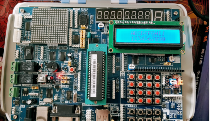
Figure 4-11-10
Example code:
#include <reg51.h>
sbit lcd_1602_RS=P2^6;  //Distinguish between commands and data
sbit lcd_1602_R_W=P2^5; //Read write distinction
sbit lcd_1602_E=P2^7;   //Enable signal
#define lcd_1602_data_cmd P0 / / send and receive data and commands

//Initialization function of 1602
void LCD1602_Init(void)
{
    LCD1602_WriteCmd(0x38); //Set display mode
    LCD1602_WriteCmd(0x06); //Set data pointer auto increment
    LCD1602_WriteCmd(0x0C); //Set the cursor display off and on
    LCD1602_WriteCmd(0x01); //Clear screen
}

//1602 write data
void LCD1602_WriteData(unsigned char dat)
{
    lcd_1602_RS=1;//Indicates write data
    lcd_1602_R_W=0;//Indicates a write operation
    lcd_1602_data_cmd=dat;//Data written
    lcd_1602_E=1;//High pulse
    DelayMs(5);
    lcd_1602_E=0;
}

//1602 write command
void LCD1602_WriteCmd(unsigned char cmd)
{
    lcd_1602_RS=0;
    lcd_1602_R_W=0;
    lcd_1602_data_cmd=cmd;
    lcd_1602_E=1;
    DelayMs(5);
    lcd_1602_E=0;
}

/*
Set cursor address
x : Display location
y : Number of rows displayed ; 0 indicates 1 row display ; 1 indicates the second row display
*/
void LCD1602_SetCursorAddr(unsigned char x,unsigned char y)
{
    unsigned char addr=0;
    if(y==1) //Indicates that the settings are displayed on line 2
    {
        addr=x+0x40;  //Second line address
    }
    else
    {
        addr=x+0x00;    //First line address
    }
    LCD1602_WriteCmd(0x80|addr); //Add 0x80 to set the address
}

/*
Set displayed data
*dat :Represents the data to display
len  :Displays the length of the data
*/
void LCD1602_DisplayData(unsigned  char *dat,unsigned char len)
{
     while(len--)
     {
         LCD1602_WriteData(*dat++);
     }
}
code u8 str1[]="ABCDEFGHIJ";  //End of string '\ 0'
code u8 str2[]="1234567890";  //End of string '\ 0'
int main()
{
    LCD1602_Init();  //1602 initialization
    DelayMs(50);
    LCD1602_SetCursorAddr(0x3,0x0);  //Set cursor address
    LCD1602_DisplayData(str1,strlen(str1)); //Display data on 1602
    LCD1602_SetCursorAddr(0x3,0x1);  //Set cursor address
    LCD1602_DisplayData(str2,strlen(str2)); //Display data on 1602
    while(1)
    {

}
}