1. VLAN Technology Principle
The following problems existed in the early bus-based local area network (LAN):
- Conflict can occur if there are currently multiple nodes sending data at the same time.
- Data sent by any node will be sent to other nodes to form a broadcast.
- All nodes share the same transmission channel, so the security of information transmission is poor.
That is to say, in the early traditional LAN, there were some problems, such as conflict domain, broadcast domain, which could not guarantee the security of information transmission; especially when more and more computers in the network, these problems were particularly obvious. Virtual LAN (VLAN) just solves these problems. VLAN can realize the isolation of broadcast domain and the safe transmission of information in LAN.
VLAN technology is mainly deployed in data link layer to isolate two-tier traffic.
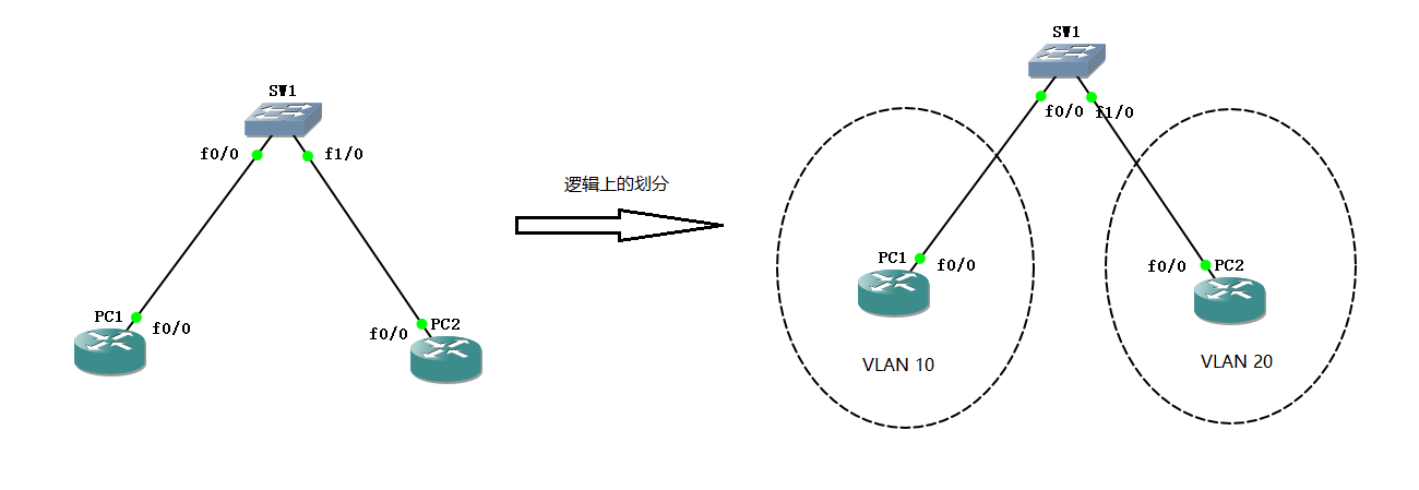
VLAN technology can logically divide a physical LAN into multiple VLANs. The original PC1 and PC2 in the figure above are in the same LAN, but through VLAN technology we divide PC1 into VLAN 10, PC2 into VLAN 20. Because PC1 and PC2 are now in different VLANs, the broadcast domain is isolated, which means that they cannot communicate directly with each other in two layers.
Only the host of the same VLAN can communicate directly in the second layer and share the same broadcast domain.
2. Scope of VLAN
The division scope of VLAN:
0 and 4095: System only, users can't view and use these VLAN s
1: Cisco's default vlan, which users can use but cannot delete
2-1001: Users can create, use and delete the range of Ethernet VLAN at will
1006 - 1024: Users cannot view and use these VLAN s for system use only
1025 - 4094: Expanding VLAN for Ethernet only
3. Experiments on VLAN partitioning and deployment
VLAN divides the steps of experimental deployment:
- Create VLAN
- Put the interface into a specific VLAN
Before that, we configure the IP address information of PC1 and PC2, which is skipped here. (If you don't know how to configure the IP address of children's shoes, you can turn over the previous article.)
In general, all ports of the switch are VLAN 1-based and can be viewed through the show command:
SW1#show vlan-switch brief

VLAN Name                             Status    Ports
---- -------------------------------- --------- -------------------------------
1    default                          active    Fa2/0, Fa2/1, Fa2/2, Fa2/3
                                                Fa2/4, Fa2/5, Fa2/6, Fa2/7
                                                Fa2/8, Fa2/9, Fa2/10, Fa2/11
                                                Fa2/12, Fa2/13, Fa2/14, Fa2/15
1002 fddi-default                     active
1003 token-ring-default               active
1004 fddinet-default                  active
1005 trnet-default                    active
From the information given by the show command, we can see that PC 1 and PC2 are in the same VLAN, that is, the default VLAN 1, so PC1 and PC2 can communicate directly.
Next, we need to divide and deploy the VLAN and go to SW1 switch to create VLAN:
//Enter VLAN database to create VLAN
SW1#vlan database
//Select the vlan 10 database and name it VLAN10
SW1(vlan)#vlan 10 name VLAN10
VLAN 10 modified:
Name: VLAN10
//Select the vlan 20 database and name it vlan 20
SW1(vlan)#vlan 20 name VLAN20
VLAN 20 modified:
    Name: VLAN20
SW1(vlan)#exit
APPLY completed.
Exiting....
SW1#
Then the switch ports are divided into specific VLAN:
SW1#conf t
Enter configuration commands, one per line.  End with CNTL/Z.
SW1(config)#int f2/0
//Set the f2/0 port of the switch to access mode, indicating that the port is used to connect computers.
SW1(config-if)#switchport mode access
//Divide the port into vlan 10
SW1(config-if)#switchport access vlan 10
//Ditto
SW1(config-if)#int f2/1
SW1(config-if)#switchport mode access
//Divide ports into vlan 20
SW1(config-if)#switchport access vlan 20
View the VLAN information of the switch again through the show command:
SW1#show vlan-switch brief

VLAN Name                             Status    Ports
---- -------------------------------- --------- -------------------------------
1    default                          active    Fa2/2, Fa2/3, Fa2/4, Fa2/5
                                                Fa2/6, Fa2/7, Fa2/8, Fa2/9
                                                Fa2/10, Fa2/11, Fa2/12, Fa2/13
                                                Fa2/14, Fa2/15
10   VLAN10                           active    Fa2/0
20   VLAN20                           active    Fa2/1
1002 fddi-default                     active
1003 token-ring-default               active
1004 fddinet-default                  active
1005 trnet-default                    active
From the vlan configuration information of the switch, we can see that VLAN 10 and VLAN 20 are at different ports.
Test network connectivity:
PC1#ping 192.168.1.2

Type escape sequence to abort.
Sending 5, 100-byte ICMP Echos to 192.168.1.2, timeout is 2 seconds:
.....
Success rate is 0 percent (0/5)
At this time, when PC1 goes to ping PC2, it can't communicate directly with the second layer, because now PC1 and pc2 do VLAN isolation in different VLAN, so they can't communicate directly.