This paper shows the identification operation of STM32 external interrupt EXTI
The content involves:
Identification of external interrupt EXTI
IO port input and output
External interrupt processing of key
External interrupt capture method
preface
Here we only explain the code of the core part. The setting of some variables and the inclusion of header files may not be involved. For the complete code, please refer to the supporting projects in this chapter. In order to make the project more organized, we store the codes related to LED light control independently, which is convenient for transplantation in the future. Create "RCC_book.c" and "RCC_book.h" files and the previous "Led_book.c" and "Led_book.h" files on the "project template": Git code
1, Programming points
External interrupt:1) Initialize the GPIO used to generate interrupts and enable an interrupt in the peripheral
2) Initialize EXTI
a: Initialize NVIC_InitTypeDef structure, configure interrupt priority grouping, set preemption priority and sub priority, and enable interrupt requests
b:NVIC_IROChannel: used to set the interrupt source
c:NVIC_IRQChannelPreemptionPriority: Preemption priority
d:NVIC_IRQChannelSubPriority
e:NVIC_IRQChannelCmd: interrupt ENABLE or DISABLE
3) Configure NVIC
4) Write interrupt service function
2, Use steps
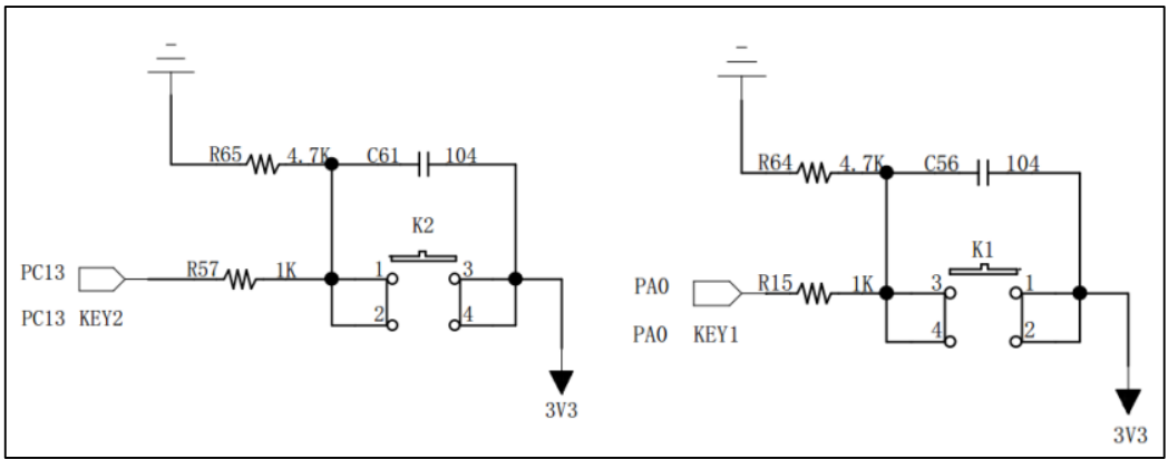
1. Understand schematic diagram
,
The code is as follows:
: STM32F103ZET6 output port is valid for PB5 low level point
: STM32F103ZET6 Key detection pin is PA8
2. Create the header file exit of exi keyboard interrupt_ book. h
The code is as follows (example):
#ifndef  __EXIT_BOOK_H_
#define  __EXIT_BOOK_H_

#include "stm32f10x.h"

#define  _KEY_EXTI_IN_GPIO_Port      GPIOA
#define  _KEY_EXTI_IN_GPIO_Pin       GPIO_Pin_0
#define  _EXTI_IN_GPIO_PortSource     GPIO_PortSourceGPIOA
#define  _EXTI_IN_GPIO_PinSource      GPIO_PinSource0
#define  _EXTI_IN_EXTI_Line           EXTI_Line0
#define  _EXTI_IN_EXTI_Trigger        EXTI_Trigger_Rising
#define  _EXTI_IN_GPIO_Clock          RCC_APB2Periph_AFIO
#define  _EXTI_IN_EXTI_Mode           EXTI_Mode_Interrupt
#define  _EXTI_IN_EXTI_LineCmd        ENABLE

#define  _NVIC_IN_EXTI_IRQChannel     EXTI0_IRQn
#define  _NVIC_IN_EXTI_IRQChannelCmd  ENABLE


#define  _KEY2_EXTI_IN_GPIO_Port     GPIOC
#define  _KEY2_EXTI_IN_GPIO_Pin      GPIO_Pin_13
#define  _EXTI_IN2_GPIO_PortSource    GPIO_PortSourceGPIOC
#define  _EXTI_IN2_GPIO_PinSource     GPIO_PinSource13
#define  _EXTI_IN2_EXTI_Line          EXTI_Line13
#define  _EXTI_IN2_EXTI_Trigger       EXTI_Trigger_Falling
#define  _EXTI_IN2_GPIO_Clock         RCC_APB2Periph_AFIO
#define  _EXTI_IN2_EXTI_Mode          EXTI_Mode_Interrupt
#define  _EXTI_IN2_EXTI_LineCmd       ENABLE

#define  _NVIC_IN2_EXTI_IRQChannel    EXTI15_10_IRQn
#define  _NVIC_IN2_EXTI_IRQChannelCmd  ENABLE


void  fn_EXTI_GPIO_Config(void);
void  fn_NVIC_Config(void);
void  EXTI0_IRQHandler(void);

#endif
3. Create the header file exit of exi keyboard interrupt_ book. c
The code is as follows (example):
#include "Exit_book.h"
#include "Led_book.h"

/**************************************************************
* @brief
* void  fn_EXTI_GPIO_Config(void)
* @param
*
*   #define  _KEY_EXTI_IN_GPIO_Port      GPIOA
*   #define  _KEY_EXTI_IN_GPIO_Pin       GPIO_Pin_0
*   #define  _EXTI_IN_GPIO_PortSource     GPIO_PortSourceGPIOA
*   #define  _EXTI_IN_GPIO_PinSource      GPIO_PinSource0
*   #define  _EXTI_IN_EXTI_Line           EXTI_Line0
*   #define  _EXTI_IN_EXTI_Trigger        EXTI_Trigger_Rising
*   #define  _EXTI_IN_GPIO_Clock          RCC_APB2Periph_AFIO
*   #define  _EXTI_IN_EXTI_Mode           EXTI_Mode_Interrupt
*   #define  _EXTI_IN_EXTI_LineCmd        ENABLE
*
*   #define  _KEY2_EXTI_IN_GPIO_Port     GPIOC
*   #define  _KEY2_EXTI_IN_GPIO_Pin      GPIO_Pin_13
*   #define  _EXTI_IN2_GPIO_PortSource    GPIO_PortSourceGPIOC
*   #define  _EXTI_IN2_GPIO_PinSource     GPIO_PinSource13
*   #define  _EXTI_IN2_EXTI_Line          EXTI_Line13
*   #define  _EXTI_IN2_EXTI_Trigger       EXTI_Trigger_Falling
*   #define  _EXTI_IN2_GPIO_Clock         RCC_APB2Periph_AFIO
*   #define  _EXTI_IN2_EXTI_Mode          EXTI_Mode_Interrupt
*   #define  _EXTI_IN2_EXTI_LineCmd       ENABLE
* @retval
*************************************************************/
void  fn_EXTI_GPIO_Config(void){
  EXTI_InitTypeDef   EXIT_InitStruck;
  RCC_APB2PeriphClockCmd(_EXTI_IN_GPIO_Clock , ENABLE);
  //Note: in addition to opening the port clock of GPIO, we also opened the clock of AFIO
  GPIO_EXTILineConfig(_EXTI_IN_GPIO_PortSource | _EXTI_IN2_GPIO_PortSource , _EXTI_IN_GPIO_PinSource | _EXTI_IN2_GPIO_PinSource);
  /* Select signal source of EXTI */
  // GPIO_ The exilineconfig function is used to specify the input source of the interrupt / event line. It actually sets the external interrupt configuration
  // Afio setting register_ Exicrx value. This function receives two parameters. The first parameter specifies the GPIO port source, and the second parameter specifies the GPIO port source
  // The second parameter is to select the corresponding GPIO pin source number.


  EXIT_InitStruck.EXTI_Line = _EXTI_IN_EXTI_Line ; /* Select signal source of EXTI */
  EXIT_InitStruck.EXTI_Mode = _EXTI_IN_EXTI_Mode;   /* EXTI Interrupt mode */
  EXIT_InitStruck.EXTI_Trigger = _EXTI_IN_EXTI_Trigger ; /* Rising edge interrupt */
  EXIT_InitStruck.EXTI_LineCmd = _EXTI_IN_EXTI_LineCmd; /* Enable interrupt */
  EXTI_Init(&EXIT_InitStruck);
  //  EXTI initializes the configured variables
  //  fn_NVIC_Config();
  //  Call NVIC_ The configuration function completes the priority configuration of key 1 and key 2 and enables the channel to be interrupted

  EXIT_InitStruck.EXTI_Line = _EXTI_IN2_EXTI_Line; /* Select signal source of EXTI */
  EXIT_InitStruck.EXTI_Mode = _EXTI_IN2_EXTI_Mode;   /* EXTI Interrupt mode */
  EXIT_InitStruck.EXTI_Trigger = _EXTI_IN2_EXTI_Trigger; /* Falling edge interrupt */
  EXIT_InitStruck.EXTI_LineCmd = _EXTI_IN_EXTI_LineCmd;/* Enable interrupt */
  EXTI_Init(&EXIT_InitStruck);

  fn_NVIC_Config();
}

/**************************************************************
* @brief
* void  fn_NVIC_Config(void)
* @param
*   #define  _NVIC_IN_EXTI_IRQChannel     EXTI0_IRQn
*   #define  _NVIC_IN_EXTI_IRQChannelCmd  ENABLE
*   #define  _NVIC_IN2_EXTI_IRQChannel    EXTI15_10_IRQn
*   #define  _NVIC_IN2_EXTI_IRQChannelCmd  ENABLE
* @retval
*************************************************************/
void  fn_NVIC_Config(void){
  NVIC_InitTypeDef NVIC_InitStruct;
  /* Configure NVIC as priority group 1 */
  NVIC_PriorityGroupConfig(NVIC_PriorityGroup_1);

  /* Configure interrupt source:  */
  NVIC_InitStruct.NVIC_IRQChannel = _NVIC_IN_EXTI_IRQChannel; //EXTI0_IRQn;
  /* Configure preemption priority: 1 */
  NVIC_InitStruct.NVIC_IRQChannelPreemptionPriority = 1;
  /* Configure sub priority: 1 */
  NVIC_InitStruct.NVIC_IRQChannelSubPriority = 1;
  /* Enable interrupt channel */
  NVIC_InitStruct.NVIC_IRQChannelCmd = _NVIC_IN_EXTI_IRQChannelCmd; //ENABLE
  NVIC_Init(&NVIC_InitStruct);

  /* Configure interrupt source:  */
  NVIC_InitStruct.NVIC_IRQChannel = _NVIC_IN2_EXTI_IRQChannel; //EXTI0_IRQn;
  NVIC_Init(&NVIC_InitStruct);
}

/**************************************************************
* @brief
* void  fn_NVIC_Config(void)
* @param
*   #define   _KEY_EXTI_IN_GPIO_Port      GPIOA
*   #define   _KEY_EXTI_IN_GPIO_Pin       GPIO_Pin_0
* @retval
*************************************************************/
void EXTI0_IRQHandler(void){
//  EXTI_GetITStatus function is used to obtain the interrupt flag bit status of exti. If there is an interrupt occurrence function on exti line
//The number returns "SET", otherwise it returns "RESET". In fact, exti_ The getitstatus function reads
//EXTI_PR register value to judge the status of the exti line.
  if(EXTI_GetITStatus(_EXTI_IN_EXTI_Line)!= RESET){
    if(GPIO_ReadInputDataBit(_KEY_EXTI_IN_GPIO_Port, _KEY_EXTI_IN_GPIO_Pin)==1){
      __LED_Change__;
    }
  }
  EXTI_ClearITPendingBit(_EXTI_IN_EXTI_Line);  // Important clear interrupt flag bit
}


void EXTI15_10_IRQHandler(void){
 if(EXTI_GetITStatus(_EXTI_IN2_EXTI_Line)!= RESET){
    if(GPIO_ReadInputDataBit(_KEY2_EXTI_IN_GPIO_Port, _KEY2_EXTI_IN_GPIO_Pin)==0){
      __LED_Change__;
    }
  }
  EXTI_ClearITPendingBit(_EXTI_IN2_EXTI_Line);  // Important clear interrupt flag bit
}
4. Create the header file Key for Key collection_ book. h
The code is as follows (example):
#ifndef  __KEY_BOOK_H_
#define  __KEY_BOOK_H_


#include "stm32f10x.h"
#include "Led_book.h"

#define   KEY_IN_GPIO_Port      GPIOA
#define   KEY_IN_GPIO_Clock     RCC_APB2Periph_GPIOA
#define   KEY_IN_GPIO_Pin       GPIO_Pin_0
#define   KEY_IN_GPIO_Pin_Bit   0
#define   Key_IN_GPIO_Modle     GPIO_Mode_IN_FLOATING / / floating input


#define   KEY2_IN_GPIO_Port      GPIOC
#define   KEY2_IN_GPIO_Clock     RCC_APB2Periph_GPIOC
#define   KEY2_IN_GPIO_Pin       GPIO_Pin_13
#define   KEY2_IN_GPIO_Pin_Bit   13
#define   Key2_IN_GPIO_Modle     GPIO_Mode_IN_FLOATING / / floating input


typedef union {
  struct{
    unsigned char BIT0:1;unsigned char BIT1:1;unsigned char BIT2:1;unsigned char BIT3:1;
    unsigned char BIT4:1;unsigned char BIT5:1;unsigned char BIT6:1;unsigned char BIT7:1;
    //unsigned char BIT8:1;unsigned char BIT9:1;unsigned char BIT10:1;unsigned char BIT11:1;
    //unsigned char BIT12:1;unsigned char BIT13:1;unsigned char BIT14:1;unsigned char BIT15:1;
  }DATA_BIT;
  uint8_t DATA_BYTE;
}Per_key_type;

extern volatile  Per_key_type key_flag;
  #define bkey_10ms         key_flag.DATA_BIT.BIT0
  #define bkey_judge        key_flag.DATA_BIT.BIT1
  #define bkey_judge_long   key_flag.DATA_BIT.BIT2
  #define bkey_Effect       key_flag.DATA_BIT.BIT3
  #define bkey_LongEffect   key_flag.DATA_BIT.BIT4
  #define bkey_Effect_Lose  key_flag.DATA_BIT.BIT5
  #define bkey_Effect_LLose key_flag.DATA_BIT.BIT6
void  fn_Key_GPIO_Config( GPIO_TypeDef* _GPIO_x , uint32_t _GPIO_Clock , uint16_t _GPIO_Pin_x , GPIOMode_TypeDef  _GPIOMode_TypeDef );
void  fn_Key_Init(void);
void  fn_key_judge(void);
void  fn_key_Effect(void);
void  fn_key_Check(void);
#endif
5. Create the header file Key for Key collection_ book. c
The code is as follows (example):
#include  "Key_book.h"

volatile  Per_key_type key_flag;

/**************************************************************
* @brief
* void  fn_Key_GPIO_Config( GPIO_TypeDef* _GPIO_x , uint32_t _GPIO_Clock ,
*                  uint16_t _GPIO_Pin_x , GPIOMode_TypeDef  _GPIOMode_TypeDef );
* @param
*     #define   KEY_IN_GPIO_Port      GPIOA
*     #define   KEY_IN_GPIO_Clock     RCC_APB2Periph_GPIOA
*     #define   KEY_IN_GPIO_Pin       GPIO_Pin_0
*     #define   KEY_IN_GPIO_Pin_Bit   0
*     #define   Key_IN_GPIO_Modle     GPIO_Mode_IN_FLOATING   //Floating input
*
*     #define   KEY2_IN_GPIO_Port      GPIOC
*     #define   KEY2_IN_GPIO_Clock     RCC_APB2Periph_GPIOC
*     #define   KEY2_IN_GPIO_Pin       GPIO_Pin_13
*     #define   KEY2_IN_GPIO_Pin_Bit   13
*     #define   Key2_IN_GPIO_Modle     GPIO_Mode_IN_FLOATING   //Floating input
* @retval
*************************************************************/
void  fn_Key_GPIO_Config( GPIO_TypeDef* _GPIO_x , uint32_t _GPIO_Clock , uint16_t _GPIO_Pin_x , GPIOMode_TypeDef  _GPIOMode_TypeDef ){
    GPIO_InitTypeDef  GPIO_InitStruct;
    GPIO_InitStruct.GPIO_Mode = _GPIOMode_TypeDef;
    GPIO_InitStruct.GPIO_Pin = _GPIO_Pin_x;
    RCC_APB2PeriphClockCmd(_GPIO_Clock,ENABLE);
    GPIO_Init(_GPIO_x , &GPIO_InitStruct);
}

/**************************************************************
* @brief
* void fn_Key_Init(void);
* @param
* @retval
*************************************************************/
void  fn_Key_Init(void){
    fn_Key_GPIO_Config(KEY_IN_GPIO_Port,KEY_IN_GPIO_Clock,KEY_IN_GPIO_Pin,Key_IN_GPIO_Modle);
    fn_Key_GPIO_Config(KEY2_IN_GPIO_Port,KEY2_IN_GPIO_Clock,KEY2_IN_GPIO_Pin,Key2_IN_GPIO_Modle);
}

/************************************************************
* @brief
* void  fn_key_judge(void);
* @param
* @retval
**************************************************************/
#define  _LONG_key  30
static uint16_t count_key ;
void  fn_key_judge(void){

   if(!bkey_10ms){return;}
   bkey_10ms = 0;
   if(GPIO_ReadInputDataBit(KEY_IN_GPIO_Port,KEY_IN_GPIO_Pin)){
     if(count_key++<3){return;}
     if(!bkey_judge){
       bkey_judge = 1;
       bkey_Effect = 1;
     }else{
       if(count_key>_LONG_key){
          bkey_judge_long = 1;
          bkey_LongEffect = 1;
       }
     }
   }
   else{
     count_key = 0;
     if(bkey_judge){
        bkey_judge = 0;
        if(bkey_judge_long){
            bkey_judge_long = 0;
            bkey_Effect_LLose = 1;
        }else{
            bkey_judge_long = 0;
            bkey_Effect_Lose = 1;
        }
     }else{
        bkey_judge = 0;
     }
  }
}

/************************************************************
* @brief
* void fn_key_Effect(void);
* @param
* @retval
*************************************************************/
void  fn_key_Effect(void){
  if(bkey_Effect){
    bkey_Effect = 0;
    fn_LED_Corporate(LED_OUT_GPIO_Port,LED_OUT_GPIO_Pin,LED_Corporate_Toggle);
  }
}

/**************************************************************
* @brief
* void fn_key_Check(void);
* @param
* @retval
*************************************************************/
void fn_key_Check(void){
  fn_key_judge();
  fn_key_Effect();
}
6. Use the previous LED output header file Led_book.h
The code is as follows (example):
#ifndef  __LED_BOOK_H_
#define  __LED_BOOK_H_

#include "stm32f10x.h"


#define   LED_OUT_GPIO_Port     GPIOB                 //GPIO Point
#define   LED_OUT_GPIO_Clock    RCC_APB2Periph_GPIOB  //GPIO clock
#define   LED_OUT_GPIO_Pin      GPIO_Pin_5
#define   LED_OUT_GPIO_Pin_Bit  5
#define   LED_OUT_GPIO_Modle    GPIO_Mode_Out_PP

typedef enum {
		LED_Corporate_On = 1,
		LED_Corporate_OFF = 2,
		LED_Corporate_Toggle = 3,
} LED_Corporate_state_t;

void fn_LED_GPIO_Config(GPIO_TypeDef* _GPIO_x , uint32_t _GPIO_Clock ,\
          uint16_t _GPIO_Pin_x , GPIOMode_TypeDef _GPIOMode_TypeDef);
void fn_Led_Init(void);
void fn_LED_Corporate(GPIO_TypeDef* _GPIO_x , uint16_t _GPIO_Pin_x , \
          LED_Corporate_state_t _LED_Corporate_state_t );

#define __LED_Change__  fn_LED_Corporate(LED_OUT_GPIO_Port,LED_OUT_GPIO_Pin,LED_Corporate_Toggle)
#endif
7. Use the header file LED output by the previous Led_book.c
The code is as follows (example):
#include "Led_book.h"

/**************************************************************
* @brief
* void fn_LED_GPIO_Config(GPIO_TypeDef* _GPIO_x , uint32_t _GPIO_Clock ,
*             uint16_t _GPIO_Pin_x , GPIOMode_TypeDef _GPIOMode_TypeDef);
* @param
* @retval
*************************************************************/
#define LED_GPIO_Speed GPIO_Speed_10MHz
void fn_LED_GPIO_Config(GPIO_TypeDef* _GPIO_x , uint32_t _GPIO_Clock ,uint16_t _GPIO_Pin_x , GPIOMode_TypeDef _GPIOMode_TypeDef){
  GPIO_InitTypeDef  GPIO_InitStruct;
  GPIO_InitStruct.GPIO_Mode = _GPIOMode_TypeDef;
  GPIO_InitStruct.GPIO_Pin = _GPIO_Pin_x;
  GPIO_InitStruct.GPIO_Speed = LED_GPIO_Speed;
  RCC_APB2PeriphClockCmd(_GPIO_Clock ,ENABLE);
  GPIO_Init(_GPIO_x , &GPIO_InitStruct) ;
  GPIO_SetBits(_GPIO_x,_GPIO_Pin_x);
}

/**************************************************************
* @brief
* void fn_Led_Init(void);
* @param
* @retval
*************************************************************/
void fn_Led_Init(void){
  fn_LED_GPIO_Config (LED_OUT_GPIO_Port,LED_OUT_GPIO_Clock,LED_OUT_GPIO_Pin,LED_OUT_GPIO_Modle);
}

/**************************************************************
* @brief
* void fn_LED_Corporate(GPIO_TypeDef*  _GPIO_x , uint16_t  _GPIO_Pin_x ,
*            LED_Corporate_state_t  _LED_Corporate_state_t );
* @param
* @retval
*************************************************************/
void fn_LED_Corporate(GPIO_TypeDef*  _GPIO_x , uint16_t  _GPIO_Pin_x , LED_Corporate_state_t  _LED_Corporate_state_t ){
  switch(_LED_Corporate_state_t){
    case  LED_Corporate_On :
      GPIO_SetBits(_GPIO_x,_GPIO_Pin_x);
      break;
		case  LED_Corporate_OFF:
      GPIO_ResetBits(_GPIO_x,_GPIO_Pin_x);
      break;
		case  LED_Corporate_Toggle:
      GPIO_ReadOutputDataBit(_GPIO_x,_GPIO_Pin_x)?GPIO_ResetBits(_GPIO_x,_GPIO_Pin_x):GPIO_SetBits(_GPIO_x,_GPIO_Pin_x);
      break;
  }
}


//practice
//fn_LED_GPIO_Config (LED_OUT_GPIO_Port,LED_OUT_GPIO_Clock,LED_OUT_GPIO_Pin,LED_OUT_GPIO_Modle);
// while(1){
//  delay(10000);
//  fn_LED_Corporate(LED_OUT_GPIO_Port,LED_OUT_GPIO_Pin,LED_Corporate_Toggle);
// }
8. Set up the main program of the Systicks Key output main c
The code is as follows (example):
/**
  ******************************************************************************
  * @file    GPIO/JTAG_Remap/main.c
  * @author  MCD Application Team
  * @version V3.5.0
  * @date    08-April-2011
  * @brief   Main program body
  ******************************************************************************
  * @attention
  *
  *
  ******************************************************************************
  */

/* Includes ------------------------------------------------------------------*/
#include "stm32f10x.h"
#include "PROJ_book.h"

/* Private functions ---------------------------------------------------------*/

/**
  * @brief  Main program.
  * @param  None
  * @retval None
  */
void delay(int x);
void fn_Main_Init(void);
int main(void)
{
      fn_Led_Init();
      fn_Key_Init();
      fn_Main_Init();
      fn_EXTI_GPIO_Config();
      while(1){
       // fn_key_Check();
        delay(10000);
      }
}

void fn_Main_Init(void){
  uint16_t  count_Init = 2;
  while(count_Init-->0){
    __LED_Change__;
    fn_Systick_Delay(500,_Systick_ms);
    __LED_Change__;
    fn_Systick_Delay(100,_Systick_ms);
    __LED_Change__;
    fn_Systick_Delay(100,_Systick_ms);
    __LED_Change__;
    fn_Systick_Delay(500,_Systick_ms);
  }
}

void delay(int x){
	int y = 0xFFFFF;
	while((x--)>0){
		while((y--)>0){
			__NOP();
			__NOP();
			__NOP();
			__NOP();
			__NOP();
		}
	}
}
/******************* (C) COPYRIGHT 2011 STMicroelectronics *****END OF FILE****/
www.firebbs.cn.
Reference notes.
_ STM32f103 interrupt and EXT
STM32 EXIT – LED program
STM32 EXIT – EXIT program
STM32 EXIT – Key program
STM32 RCC - main program
summary
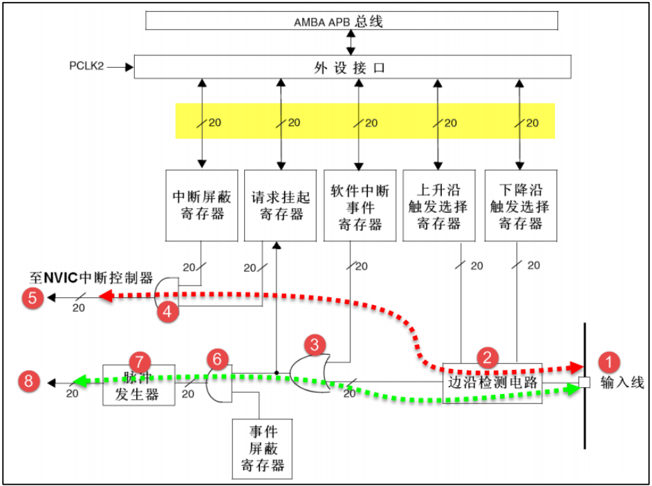
EXTI(External interrupt/event controller)—External interrupt/Event controller, which manages 20 of the controller
 Interrupts/Event line. Each interrupt/Each event line corresponds to an edge detector, which can realize the rising edge of the input signal
 Detection and falling edge detection. EXTI Each interrupt can be implemented/The event line can be configured separately as
 Interrupt or event, and the properties of the trigger event.
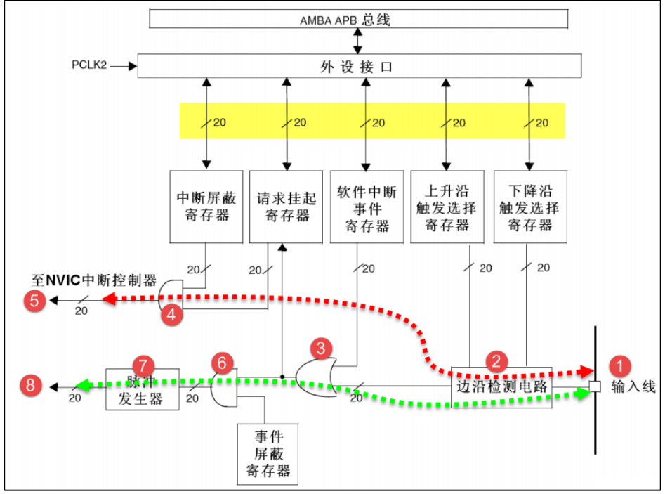
EXTI The functional block diagram includes EXTI The core content, master the functional block diagram, right EXTI There is a whole
When programming, the idea is very clear. EXTI The functional block diagram is shown in Figure 18-1. In Figure 18-1 You can see that many people put a slash on the signal line and mark the word "20", which indicates that it is in the controller
There are 20 internal similar signal lines, which is similar to EXTI There are 20 interrupts in total/The event line is consistent. So we just
To understand the principle of one of them, you can know the principle of the other 19 lines
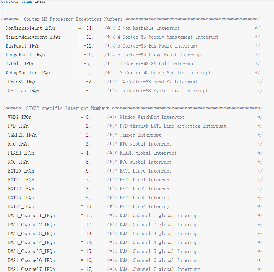
EXTI0 to EXTI15 be used for GPIO,Any one can be realized through programming control GPIO As EXTI Lose
Incoming source. From table 18-1 You know, EXTI0 Can pass AFIO External interrupt configuration register 1(AFIO_EXTICR1)of
EXTI0[3:0]Bit selection configuration is PA0,PB0,PC0,PD0,PE0,PF0,PG0,PH0 or
EXTI Detailed explanation of initialization structure
The standard library function establishes an initialization structure for each peripheral, such as EXTI_InitTypeDef,structural morphology
Member is used to set the working parameters of the peripheral, and the peripheral initializes the configuration function, such as EXTI_Init()Call, these settings
The parameter will set the corresponding register of the peripheral to achieve the purpose of configuring the working environment of the peripheral
typedef struct {
2 uint32_t EXTI_Line; // Interrupt / event line
3 EXTIMode_TypeDef EXTI_Mode; // EXTI mode
4 EXTITrigger_TypeDef EXTI_Trigger; // Trigger type
5 FunctionalState EXTI_LineCmd; // EXTI enable
6 } EXTI_InitTypeDef;
1. First, press the key and EXTI Macro definition uses the macro definition method to specify the configuration related to hardware circuit design, which is very useful for program transplantation or upgrade. In the macro definition above, we can only open GPIO In addition to the port clock, we also turned it on AFIO This is because of the configuration later EXTI The signal source needs to be used AFIO External interrupt control register AFIO_EXTICRx
2. Nested vector interrupt controller NVIC Configure, configure the priority of two interrupt software
3. EXTI Interrupt configuration
4. use GPIO_InitTypeDef and EXTI_InitTypeDef Structure defines two for GPIO and EXTI Initialization configuration variables. The two structures have been explained in detail before.
use GPIO Must be turned on before GPIO Clock of port; be used EXTI Must be on AFIO Clock.
call NVIC_Configuration Function to configure the key priority and enable the interrupt channel.
As interrupt/Event input line GPIO It is configured as input mode, specifically floating input, and the state of the pin is completely determined by the external circuit. GPIO_EXTILineConfig Function to specify an interrupt/The input source of the event line, which actually sets the external interrupt configuration register AFIO_EXTICRx Value, the function receives two parameters, and the first parameter specifies GPIO Port source, the second parameter is the corresponding selection GPIO Pin source number.
Our purpose is to generate interrupts and execute interrupt service functions, EXTI Select the interrupt mode, press key 1 to use the rising edge trigger mode and enable EXTI Line. Key 2 basically adopts the parameter configuration related to key 1, but it is changed to the falling edge trigger mode