SPI
This article shows STM32 SPI Transfer
The content involves:
SPI byte data analog output independent write cache read and write
Identification of USART serial port
IO port input / output
External interrupt processing of key
32-bit data communication, string communication, single character communication
Full code:
: GIT source code
preface
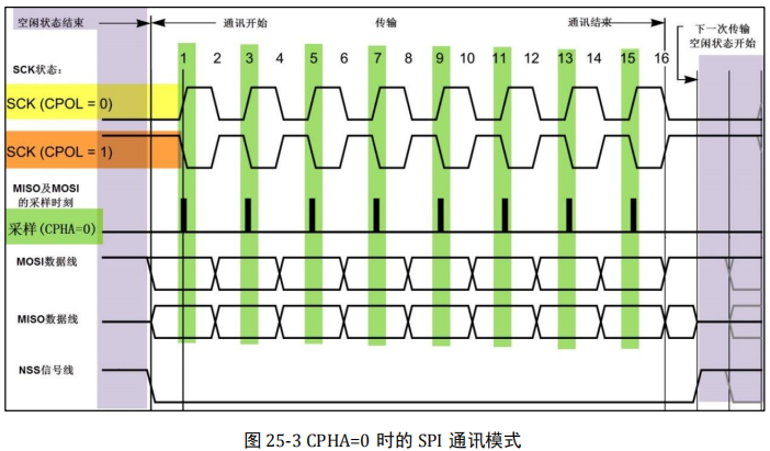
Introduction to spi of STM32 SPI protocol is a communication protocol (Serial Peripheral Interface) proposed by Motorola, that is, serial peripheral interface. It is a high-speed full duplex communication bus. It is widely used between ADC, LCD and MCU, which requires high communication rate.According to the level of SCK in idle state, it can be divided into two cases. When the SCK signal line is at low level in idle state, CPOL=0; When the idle state is high, CPOL=1.
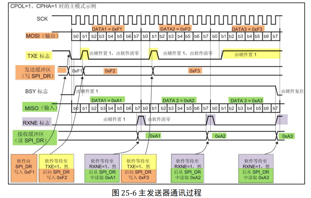
Whether CPOL=0 or = 1, because the clock phase CPHA configured by us is equal to 0, it can be seen in the figure that the sampling time is at the odd edge of SCK. Note that when CPOL=0, the odd edge of the clock is the rising edge, while when CPOL=1, the odd edge of the clock is the falling edge. Therefore, the sampling time of SPI is not determined by the rising / falling edge. The effective signals of MOSI and MISO data lines remain unchanged at the odd edge of SCK, and the data signals will be sampled at the odd edge of SCK. At the non sampling time, the effective signals of MOSI and MISO will be switched.
SPI communication protocol is a very concise communication protocol from the physical layer. There are two buses in total, one SCL (clock bus) and one SDA (data bus). The communication principle is to generate the signals required by I2C bus protocol for data transmission by controlling the high and low level timing of SCL and SDA lines. When the bus is idle, these two lines are generally pulled up by the pull-up resistance connected above to maintain the high level (original link: ttps://blog.csdn.net/qq_42660303/article/details/81154995 )
1, Programming points
SPI:(1) Initialize the target pin and port clock used for communication
(2) Enable SPI peripheral clock
(3) Configure the mode, address, rate and other parameters of SPI peripherals and enable SPI peripherals
(4) Write the function of sending and receiving basic SPI by bytes;
(5) Write functions for FLASH erase and read / write operations
(6) Write a test program to verify the read and write data
2, Use steps
1. Understand schematic diagram
Communication process
(note) Keil configuration status
My blog has project configuration design here;
Click the link
(https://blog.csdn.net/u012651389/article/details/119189949)
2. Establish the main program main c
Insert picture description here
The code is as follows:
/**
******************************************************************************
* @file GPIO/JTAG_Remap/main.c
* @author MCD Application Team
* @version V3.5.0
* @date 08-April-2011
* @brief Main program body
******************************************************************************
* @attention
*
*
******************************************************************************
*/
/* Includes ------------------------------------------------------------------*/
#include "stm32f10x.h"
#include "PROJ_book.h"
/* Private functions ---------------------------------------------------------*/
/**
* @brief Main program.
* @param None
* @retval None
*/
void fn_LED_Flash_Init(void);
void fn_usart_show_Init(void);
void fn_DMA_show_Init(void);
void fn_I2C_EE_Init(void);
void fn_I2C_EE_Soft_Init(void);
void fn_SPI_FLASH_Soft_Init(void);
#define countof(a) (sizeof(a) / sizeof(*(a)))
#define _I2C_BufferSize (countof(writeData)-1)
static uint8_t writeData[_I2C_PageSize]={4,5,6,7,8,9,10,11};
static uint8_t writeData2[_I2C_PageSize]={24,25,26,27,28,29,30,31};
static uint8_t ReadData[_I2C_BufferSize]={0};
#define _SPI_BufferSize SPI_PAGE_SIZE //(countof(write_SPI_Data)-1)
static uint8_t write_SPI_Data[_SPI_BufferSize]={0};
static uint8_t Read_SPI_Data[_SPI_BufferSize]={0};
int main(void)
{
fn_RCC_Init(); //CPU frequency doubling
fn_Led_Init(); //LED output initialization
fn_Key_Init(); //Key input initialization
fn_USART_Init(); //Serial output initialization
fn_LED_Flash_Init(); //RGB output test
fn_usart_show_Init(); //Serial port output test
fn_EXTI_GPIO_Config(); //External interrupt entry
fn_DMA_show_Init(); //Initialize DMA data link
fn_I2C_EE_Init(); //Initialize hardware I2C data link
fn_I2C_EE_Soft_Init(); //Initialize the software I2C data link
fn_SPI_FLASH_Soft_Init(); //SPI test communication
while(1){
fn_LED_ALL_OFF();
fn_Systick_Delay(500,_Systick_ms);
__G_OUT__;
fn_Systick_Delay(500,_Systick_ms);
}
}
void fn_LED_Flash_Init(void){
uint16_t count_Init = 2;
printf("\n ---> LED Start running \n");
while(count_Init-->0){
fn_LED_ALL_OFF();
__R_OUT__;
fn_Systick_Delay(500,_Systick_ms);
fn_LED_ALL_OFF();
__G_OUT__;
fn_Systick_Delay(500,_Systick_ms);
fn_LED_ALL_OFF();
__B_OUT__;
fn_Systick_Delay(500,_Systick_ms);
fn_LED_ALL_OFF();
__R_OUT__;
}
}
void fn_usart_show_Init(void){
fn_Usart_Send_Byte(_DEBUG_USARTx,'\r');
printf("-->Serial communication means that the test is completed \n");
fn_Usart_SendString(_DEBUG_USARTx," : wangqi \n");
}
void fn_DMA_show_Init(void){
printf("\n ---> DMA Start running \n");
_DMA_ROM_TO_RAM(Map_BUFFER_SIZE ,aSRC_Cont_Buffer , aDST_Buffer);
_DMA_RAM_TO_USART(Map_BUFFER_SIZE ,USART_Source_ADDR , aDST_Buffer);
printf("---> DMA Operation completed \n");
}
void fn_I2C_EE_Init(void){
printf("\n-->I2C_Function write start \n");
_I2C_EE_Init();
I2C_Write_fun(writeData ,EEP_Firstpage ,_I2C_BufferSize);
I2C_Read_fun(ReadData ,EEP_Firstpage ,_I2C_BufferSize);
printf("--->I2C_Function write complete\n\r");
}
void fn_I2C_EE_Soft_Init(void){
printf("\n-->I2C_Software function write start \n");
I2C_Soft_Init();
I2C_Soft_Write_fun(writeData2 ,EEP_Firstpage ,_I2C_BufferSize);
I2C_Soft_Read_fun(ReadData ,EEP_Firstpage ,_I2C_BufferSize);
printf("\n--->I2C_Software function written\n\r");
}
void fn_SPI_FLASH_Soft_Init(void){
uint16_t i,FlashID;
printf("-->SPI Communication means the start of the test \n");
SPI_FLASH_Init();
FlashID = SPI_Read_ID() ;
if(FlashID == _SPI_FLASH_ID){
printf("-->SPI 0x%x \n",FlashID);
}
SPI_Erase_Sector(0); //Clear space for one page
printf("\n\n-->SPI Emptying start \n");
SPI_Read_Data(Read_SPI_Data , 0, SPI_PAGE_SIZE);
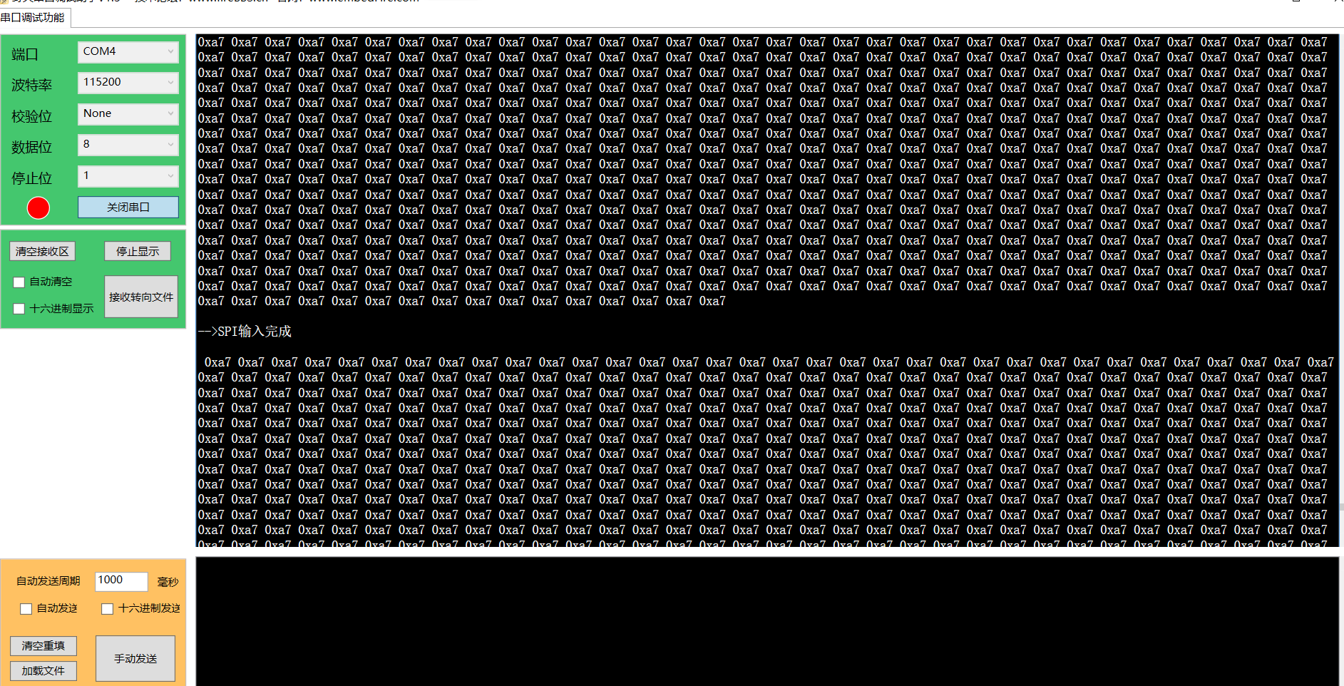
SPI_Show_Data(Read_SPI_Data , SPI_PAGE_SIZE);
printf("\n\n-->SPI Emptying complete \n");
for(i=0 ; i < _SPI_BufferSize ; i++){
write_SPI_Data[i] = 0xA7;
}
SPI_Show_Data(write_SPI_Data , SPI_PAGE_SIZE);
SPI_BufferWrite_Data(write_SPI_Data ,0x000000,_SPI_BufferSize);
printf("\n\n-->SPI Input complete \n");
SPI_Read_Data(Read_SPI_Data , 0x000000, _SPI_BufferSize);
SPI_Show_Data(Read_SPI_Data , _SPI_BufferSize);
printf("-->SPI Communication means that the test is completed \n");
}
void delay(int x){
int y = 0xFFFFF;
while((x--)>0){
while((y--)>0){
__NOP();
__NOP();
__NOP();
__NOP();
__NOP();
}
}
}
/******************* (C) COPYRIGHT 2011 STMicroelectronics *****END OF FILE****/
3. Establish SPI transmission header file_ book. h
The code is as follows:
#ifndef __SPI_BOOK_H_
#define __SPI_BOOK_H_
#include "stm32f10x.h"
//#define _SPI_FLASH_ID 0xEF3015 //W25X16
//#define _SPI_FLASH_ID 0xEF4015 //W25Q16
//#define _SPI_FLASH_ID 0XEF4018 //W25Q128
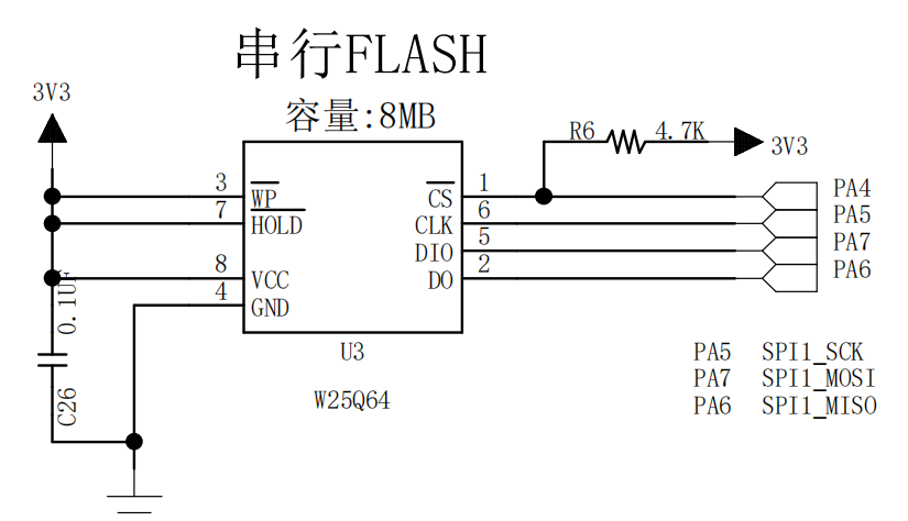
#define _SPI_FLASH_ID 0XEF4017 //W25Q64
//----------------I2C communication configuration information is encapsulated here-------------------
#define _FLASH_SPIx SPI1
#define _FLASH_SPI_APBxClock_FUN RCC_APB2PeriphClockCmd
#define _FLASH_SPI_CLK RCC_APB2Periph_SPI1
#define _FLASH_SPI_GPIO_APBxClock_FUN RCC_APB2PeriphClockCmd
#define _FLASH_SPI_GPIO_CLK RCC_APB2Periph_GPIOA
#define _FLASH_SPI_SCL_PORT GPIOA
#define _FLASH_SPI_SCL_PIN GPIO_Pin_5
#define _FLASH_SPI_MISO_PORT GPIOA
#define _FLASH_SPI_MISO_PIN GPIO_Pin_6
#define _FLASH_SPI_MOSI_PORT GPIOA
#define _FLASH_SPI_MOSI_PIN GPIO_Pin_7
#define _FLASH_SPI_CSS_PORT GPIOA
#define _FLASH_SPI_CSS_PIN GPIO_Pin_4
//FLASH_SPI pin configuration
#define _FLASH_CSS_HIGH() _FLASH_SPI_CSS_PORT->BSRR = _FLASH_SPI_CSS_PIN
#define _FLASH_CSS_LOW() _FLASH_SPI_CSS_PORT->BRR = _FLASH_SPI_CSS_PIN
/*Communication waiting timeout*/
#define FLASH_SPI_TIMEOUT ((uint32_t)0x6000)
#define FLASH_SPI_LONG_TIMEOUT ((uint32_t)(10*FLASH_SPI_TIMEOUT))
//Information output
#define FLASH_ERROR(fmt,arg...) printf("<<-FLASH-ERROR->> "fmt"\n",##arg)
//
#define SPI_PAGE_SIZE 4096
#define SPI_PAGE_Write_SIZE 256
//FLASH instruction
#define FLASH_SPI_DUMMY 0x00
#define FLASH_SPI_READ_JEDEC_ID 0x9f
#define FLASH_SPI_REASE_SECTOR 0x20
#define FLASH_SPI_READ_STATUS 0x05
#define FLASH_SPI_READ_DATA 0x03
#define FLASH_SPI_WRITE_ENABLE 0x06
#define FLASH_SPI_WRITE_DATA 0x02
#define FLASH_SPI_ChipErase 0xC7
void SPI_FLASH_Init(void);
uint32_t SPI_Read_ID(void);
uint32_t SPI_Read_DeviceID(void);
void SPI_Erase_Sector(uint32_t addr);
void SPI_FLASH_BulkErase(void);
void SPI_Read_Data(uint8_t *readBuffer , uint32_t addr ,uint16_t numByteToRead );
void SPI_BufferRead_Data(uint8_t *writeBuffer , uint32_t WriteAddr ,uint16_t numByteToWrite );
void SPI_Write_Data(uint8_t *writeBuffer , uint32_t addr ,uint16_t numByteToRead );
void SPI_BufferWrite_Data(uint8_t *writeBuffer , uint32_t WriteAddr ,uint16_t numByteToWrite );
void SPI_Show_Data(uint8_t *readBuffer , uint16_t numByteToRead);
#endif
4. Establish SPI transmission header file_ book. c
The code is as follows:
#include "SPI_book.h"
#include "Systick_book.h"


static __IO  uint32_t SPITimeout = FLASH_SPI_LONG_TIMEOUT;


/**
  * @brief  SPII/O to configure
  * @param  nothing
  * @retval nothing
  */
static void SPI_GPIO_Config(void){
  GPIO_InitTypeDef  GPIO_InitStructure;
  //Enable SPI related clocks
  _FLASH_SPI_APBxClock_FUN(_FLASH_SPI_CLK , ENABLE);
  _FLASH_SPI_GPIO_APBxClock_FUN(_FLASH_SPI_GPIO_CLK , ENABLE);

  //MISO MOSI SCK
  GPIO_InitStructure.GPIO_Pin = _FLASH_SPI_SCL_PIN;
  GPIO_InitStructure.GPIO_Speed = GPIO_Speed_50MHz;
  GPIO_InitStructure.GPIO_Mode = GPIO_Mode_AF_PP;
  GPIO_Init(_FLASH_SPI_SCL_PORT,&GPIO_InitStructure);

  GPIO_InitStructure.GPIO_Pin = _FLASH_SPI_MISO_PIN;
  GPIO_InitStructure.GPIO_Speed = GPIO_Speed_50MHz;
  GPIO_InitStructure.GPIO_Mode = GPIO_Mode_IN_FLOATING;
  GPIO_Init(_FLASH_SPI_SCL_PORT,&GPIO_InitStructure);

  GPIO_InitStructure.GPIO_Pin = _FLASH_SPI_MOSI_PIN;
  GPIO_InitStructure.GPIO_Speed = GPIO_Speed_50MHz;
  GPIO_InitStructure.GPIO_Mode = GPIO_Mode_AF_PP;
  GPIO_Init(_FLASH_SPI_SCL_PORT,&GPIO_InitStructure);

  //Initialize CSS pin to enable software control, so it is directly set to push-pull output
  GPIO_InitStructure.GPIO_Pin = _FLASH_SPI_CSS_PIN;
  GPIO_InitStructure.GPIO_Speed = GPIO_Speed_50MHz;
  GPIO_InitStructure.GPIO_Mode = GPIO_Mode_Out_PP;
  GPIO_Init(_FLASH_SPI_SCL_PORT,&GPIO_InitStructure);

  _FLASH_CSS_HIGH();
}


/**
  * @brief  static void SPI_Mode_Config(void) to configure
  * @param  nothing
  * @retval nothing
  */
static void SPI_Mode_Config(void){
  SPI_InitTypeDef  SPI_InitStructure;

  SPI_InitStructure.SPI_BaudRatePrescaler = SPI_BaudRatePrescaler_2 ; //The baud rate prescaled value is 2
  SPI_InitStructure.SPI_CPHA = SPI_CPHA_2Edge ;        //Data is captured on the second clock edge
  SPI_InitStructure.SPI_CPOL = SPI_CPOL_High;          //Clock hanging height
  SPI_InitStructure.SPI_CRCPolynomial = 0;             //The CRC function is not used, and the value is written casually
  SPI_InitStructure.SPI_DataSize = SPI_DataSize_8b;    //SPI transmit receive 8-bit frame structure
  SPI_InitStructure.SPI_Direction = SPI_Direction_2Lines_FullDuplex ; //two-wire full duplex
  SPI_InitStructure.SPI_FirstBit = SPI_FirstBit_MSB;   //Data transmission starts from the MSB bit
  SPI_InitStructure.SPI_Mode = SPI_Mode_Master ;       //Set as master SPI
  SPI_InitStructure.SPI_NSS = SPI_NSS_Soft;            //The internal NSS signal is controlled by SSI bit

  SPI_Init(_FLASH_SPIx , &SPI_InitStructure ); //Write configuration to register
  SPI_Cmd(_FLASH_SPIx , ENABLE);   //Enable SPI
}

/**
  * @brief  void SPI_FLASH_Init(void) initialization
  * @param  nothing
  * @retval nothing
  */
void SPI_FLASH_Init(void){
  SPI_GPIO_Config();
  SPI_Mode_Config();
}

//+++++++++++++++++++++++++++++++++++++++++++++++++++++++++++++++
//                         Communication establishment operation
//+++++++++++++++++++++++++++++++++++++++++++++++++++++++++++++++
/**
  * @brief  Basic management of the timeout situation.
  * @param  errorCode: Error code, which can be used to locate the error link
  * @retval Return 0, indicating SPI read failure
  */
static  uint32_t SPI_TIMEOUT_UserCallback(uint8_t errorCode)
{
  /* Block communication and all processes */
  FLASH_ERROR("SPI Wait timeout!errorCode = %d",errorCode);

  return 0;
}
/**
  * @brief  uint8_t SPI_FLASH_Send_Byte(uint8_t data) initialization
  * @param  Send and receive a byte
  * @retval nothing
  */
static uint8_t SPI_FLASH_Send_Byte(uint8_t data){
  SPITimeout = FLASH_SPI_TIMEOUT;
  //Check and wait to TX buffer
  while(SPI_I2S_GetFlagStatus(_FLASH_SPIx,SPI_I2S_FLAG_TXE) == RESET){//Send cache empty flag bit
    if(SPITimeout--==0) {return SPI_TIMEOUT_UserCallback(0);}
  }
  //Judge that the program is empty
  SPI_I2S_SendData(_FLASH_SPIx , data);
  //Judge whether the acceptance cache is not empty
  SPITimeout = FLASH_SPI_TIMEOUT;
  while(SPI_I2S_GetFlagStatus(_FLASH_SPIx,SPI_I2S_FLAG_RXNE) == RESET){//Accept cache non null flag bit
    if(SPITimeout--==0) {return SPI_TIMEOUT_UserCallback(1);}
  }
  //The program has been sent And need to receive a byte
  return SPI_I2S_ReceiveData(_FLASH_SPIx);
}

/**
  * @brief  uint8_t SPI_FLASH_Send_Byte(uint8_t data) initialization
  * @param  Send and receive a byte
  * @retval nothing
  */
static uint8_t SPI_FLASH_SendHalf_Byte(uint16_t Halfdata){
  SPITimeout = FLASH_SPI_TIMEOUT;
  //Check and wait to TX buffer
  while(SPI_I2S_GetFlagStatus(_FLASH_SPIx,SPI_I2S_FLAG_TXE) == RESET){//Send cache empty flag bit
    if(SPITimeout--==0) {return SPI_TIMEOUT_UserCallback(2);}
  }
  //Judge that the program is empty
  SPI_I2S_SendData(_FLASH_SPIx , Halfdata);
  //Judge whether the acceptance cache is not empty
  SPITimeout = FLASH_SPI_TIMEOUT;
  while(SPI_I2S_GetFlagStatus(_FLASH_SPIx,SPI_I2S_FLAG_RXNE) == RESET){//Accept cache non null flag bit
    if(SPITimeout--==0) {return SPI_TIMEOUT_UserCallback(3);}
  }
  //The program has been sent And need to receive a byte
  return SPI_I2S_ReceiveData(_FLASH_SPIx);
}

/**
  * @brief  uint32_t SPI_Read_ID(void)
  * @param  Read ID number
  * @retval
  */
uint32_t SPI_Read_ID(void){
  uint32_t flash_id;
  //Film selection enable
  _FLASH_CSS_LOW();
  SPI_FLASH_Send_Byte(FLASH_SPI_READ_JEDEC_ID);
  flash_id = SPI_FLASH_Send_Byte(FLASH_SPI_DUMMY);//Memory typeID
  flash_id<<=8;
  flash_id|=SPI_FLASH_Send_Byte(FLASH_SPI_DUMMY);//Capcity typeID
  flash_id<<=8;
  flash_id|=SPI_FLASH_Send_Byte(FLASH_SPI_DUMMY);//Capcity typeID
  _FLASH_CSS_HIGH();
  return flash_id;
}

/**
  * @brief  uint32_t SPI_Read_ID(void)
  * @param  Read ID number
  * @retval
  */
//uint32_t SPI_Read_DeviceID(void){
//  uint32_t flash_id;
//  //Film selection enable
//  _FLASH_CSS_LOW();
//  SPI_FLASH_Send_Byte(FLASH_SPI_READ_JEDEC_ID);
//  SPI_FLASH_Send_Byte(FLASH_SPI_DUMMY);//Memory typeID
//  SPI_FLASH_Send_Byte(FLASH_SPI_DUMMY);//Capcity typeID
//  SPI_FLASH_Send_Byte(FLASH_SPI_DUMMY);//Capcity typeID
//  flash_id = SPI_FLASH_Send_Byte(FLASH_SPI_DUMMY);//Capcity typeID
//  _FLASH_CSS_HIGH();
//  return flash_id;
//}

/**
  * @brief  void SPI_Write_Enable(void)
  * @param  Write enable
  * @retval
  */
static void SPI_Write_Enable(void){
  //Film selection enable
  _FLASH_CSS_LOW();
  SPI_FLASH_Send_Byte(FLASH_SPI_WRITE_ENABLE);
  _FLASH_CSS_HIGH();
}

/**
  * @brief  static void SPI_WaitForWriteEnd(void);
  * @param  //Wait for the FLASH internal timing operation to complete
  * @retval
  */
static SPI_WaitForWriteEnd(void){
  uint8_t status_reg = 0;  //Judge the lowest S0 erse or write in progress
  // Chip selection instruction
  _FLASH_CSS_LOW();
  SPI_FLASH_Send_Byte(FLASH_SPI_READ_STATUS);
  do{
    status_reg = SPI_FLASH_Send_Byte(FLASH_SPI_DUMMY); //To read data, you need to continue sending
  }while((status_reg & 0x01)==1);  //Verify the lowest bit
  _FLASH_CSS_HIGH();

}
/**
  * @brief  svoid SPI_Erase_Sector(uint32_t addr)
  * @param  Erase FLASH specified sector
  * @retval
  */
void SPI_Erase_Sector(uint32_t addr){
  SPI_Write_Enable();
  /* Erase sector */
  /* Select FLASH: CS low level */
  _FLASH_CSS_LOW();
  /* Send sector erase instruction*/
  SPI_FLASH_Send_Byte(FLASH_SPI_REASE_SECTOR);
  /*Send high bit of erase sector address*/
  SPI_FLASH_Send_Byte((addr & 0xFF0000) >> 16);
  /* Send the median of the erase sector address */
  SPI_FLASH_Send_Byte((addr & 0xFF00) >> 8);
  /* Send low order of erase sector address */
  SPI_FLASH_Send_Byte(addr & 0xFF);
  /* Stop signal FLASH: CS high level */
  _FLASH_CSS_HIGH();
  /* Wait for the erase to complete*/
  SPI_WaitForWriteEnd();
}

 /**
  * @brief  Erase the FLASH sector and erase the whole chip
  * @param  nothing
  * @retval nothing
  */
void SPI_FLASH_BulkErase(void){
  //Send FLASH write enable command
  SPI_Write_Enable();
  //Block Erase
  //Select flash: CS low level
  _FLASH_CSS_LOW();
  SPI_FLASH_Send_Byte(FLASH_SPI_ChipErase);
  /* Stop signal FLASH: CS high level */
  _FLASH_CSS_HIGH();
  /* Wait for the erase to complete*/
  SPI_WaitForWriteEnd();
}


//+++++++++++++++++++++++++++++++++++++++++++++++++++++++++++++++
//                         Read / write operation
//+++++++++++++++++++++++++++++++++++++++++++++++++++++++++++++++

/**
  * @brief  void SPI_Read_Data(uint8_t *readBuffer , uint32_t addr ,uint32_t  numByteToRead ));
  * @param  Read the contents of FLASH
  * @retval
  */
void SPI_Read_Data(uint8_t *readBuffer , uint32_t addr ,uint16_t  numByteToRead ){
  //Film selection enable
  _FLASH_CSS_LOW();
  //Sending address
  /* Send read instruction */
  SPI_FLASH_Send_Byte(FLASH_SPI_READ_DATA);
  /* Send read address high bit */
  SPI_FLASH_Send_Byte((addr>>16)&0xff);
  /* Send read address median */
  SPI_FLASH_Send_Byte((addr>>8)&0xff);
  /* Send read address low order */
  SPI_FLASH_Send_Byte(addr&0xff);

//  if(numByteToRead > SPI_PAGE_SIZE){
//    numByteToRead = SPI_PAGE_SIZE;
//    printf("SPI_FLASH_PageWrite too large!\n");
//  }
  /* Read data */
  while(numByteToRead--){
    /* Read a byte*/
    *readBuffer = SPI_FLASH_Send_Byte(FLASH_SPI_DUMMY);
    /* Point to next byte buffer */
    readBuffer++;
  }
  /* Stop signal FLASH: CS high level */
  _FLASH_CSS_HIGH();
}


/**
  * @brief  void SPI_Write_Data(uint8_t *readBuffer , uint32_t addr ,uint32_t  numByteToRead ));
  * @param  Read the contents of FLASH
  * @retval
  */
void SPI_Write_Data(uint8_t *writeBuffer , uint32_t addr ,uint16_t  numByteToRead ){
  SPI_Write_Enable();
  //Film selection enable
  _FLASH_CSS_LOW();
  /* Page write instruction*/
  SPI_FLASH_Send_Byte(FLASH_SPI_WRITE_DATA);
  /*High bit of send write address*/
  SPI_FLASH_Send_Byte((addr&0xff0000)>>16);
  /*The median of the send write address*/
  SPI_FLASH_Send_Byte((addr&0xff00)>>8);
  /*Send low order of write address*/
  SPI_FLASH_Send_Byte(addr&0xff);

  if(numByteToRead > SPI_PAGE_SIZE){
    numByteToRead = SPI_PAGE_SIZE;
    printf("SPI_FLASH_PageWrite too large!\n");
  }
  //Write data
  while(numByteToRead--){
    //Send byte data currently to be written
    SPI_FLASH_Send_Byte(*writeBuffer);
    //Point to 100 million bytes of data
    writeBuffer++;
  }
  /* Stop signal FLASH: CS high level */
  _FLASH_CSS_HIGH();
  /* Wait for writing to complete*/
  SPI_WaitForWriteEnd();
}

/**
  * @brief  SPI_Write_Data(uint8_t *writeBuffer , uint32_t addr ,uint32_t  numByteToRead ){
  * @param  Read the contents of FLASH
  * @retval
  */
void SPI_BufferWrite_Data(uint8_t *writeBuffer , uint32_t WriteAddr ,uint16_t  numByteToWrite ){
  uint32_t NumOfPage , NumOfSingle , BufferAddr ,count , temp;

  if(numByteToWrite == 0){printf("SPI_FLASH_PageWrite too small!\n"); return;}
  BufferAddr = WriteAddr % SPI_PAGE_Write_SIZE;
  /*Number of front alignments of the page corresponding to the address*/
  count = SPI_PAGE_Write_SIZE - BufferAddr;
  /*Number of all addresses left on the current page*/
  if(count >= numByteToWrite){
    //The rest can be written in one line
     SPI_Write_Data(writeBuffer ,WriteAddr ,numByteToWrite );
     return;
  }
  SPI_Write_Data(writeBuffer ,WriteAddr ,(uint16_t)count );//Split write to separate page
  temp = numByteToWrite -  count ;  //Eliminate excess parts
  WriteAddr += count;
  writeBuffer+=count;
  NumOfPage = temp / SPI_PAGE_Write_SIZE ; //For large area split input
  NumOfSingle = temp % SPI_PAGE_Write_SIZE ;

  if(NumOfPage == 0){
    SPI_Write_Data(writeBuffer ,WriteAddr ,(uint16_t)NumOfSingle );
    return;
  }else{
    while(NumOfPage--){
      SPI_Write_Data(writeBuffer ,WriteAddr ,SPI_PAGE_Write_SIZE );
      WriteAddr += SPI_PAGE_Write_SIZE;
      writeBuffer += SPI_PAGE_Write_SIZE;
    }
    SPI_Write_Data(writeBuffer ,WriteAddr ,(uint16_t)NumOfSingle );
    return;
  }

}

/**
  * @brief  void SPI_Show_Data(uint8_t *readBuffer);
  * @param  Read the contents of FLASH
  * @retval
  */
void SPI_Show_Data(uint8_t *readBuffer , uint16_t  numByteToRead){
  uint32_t i;
  for(i=0 ;i<numByteToRead ;i++ ){
    if(i%SPI_PAGE_Write_SIZE == 0){ //Wrap every 256 bytes
      printf("\r\n ");
    }
     printf("0x%x ",readBuffer[i]);
  }
}
(1) Using GPIO_InitTypeDef defines GPIO initialization structure variables to store GPIO configuration below;
(2) Call library function RCC_APB2PeriphClockCmd enables the GPIO port clock used by the SPI pin.
(3) Assign a value to the GPIO initialization structure and initialize the SCK/MOSI/MISO pin to the multiplex push-pull mode. Since the CS(NSS) pin is controlled by software, we configure it as a normal push-pull output mode.
(4) Use the configuration of the initialization structure above to call GPIO_Init function writes parameters to the register to complete the initialization of GPIO
SPI_ FLASH_ The sendbyte function implements the "SPI communication process" explained earlier: (1) this function does not contain SPI start and stop signals, but the main process of sending and receiving, so the start and stop signals should be operated before and after calling this function;
(2) Assign the SPITimeout variable to the macro SPIT_FLAG_TIMEOUT. This SPITimeout variable is subtracted by 1 each time in the following while loop, which calls the library function SPI_I2S_GetFlagStatus detects events. If an event is detected, it enters the next stage of communication. If no event is detected, it stays here for detection. When detecting spit_ FLAG_ If the timeout has not yet waited for the event, it is considered that the communication has failed and the SPI is called_ TIMEOUT_ Usercallback outputs debugging information and exits communication;
(3) Obtain the status of the transmission buffer by detecting the TXE flag. If the transmission buffer is empty, it indicates that the last possible data has been transmitted;
(4) wait until the sending buffer is empty, then call the library function SPI_. I2S_ SendData writes the data "byte" to be sent to the SPI data register DR, and the data written to the SPI data register will be stored in the transmission buffer and sent by the SPI peripheral;
(5) Wait for RXNE event after writing, that is, receive non empty buffer event. Since MOSI and MISO data transmission are synchronous under SPI two-wire full duplex mode (please refer to "SPI communication process"), when the receiving buffer is not empty, it means that the above data has been sent and the receiving buffer has also received new data;
(6) Wait until the receive buffer is not empty by calling the library function SPI_I2S_ReceiveData reads the data register DR of SPI to obtain new data in the receive buffer. The code uses the keyword "return" to take the received data as SPI_ FLASH_ The return value of the sendbyte function, so we can see the SPI receiving data function SPI defined below_ FLASH_ Readbyte, which simply calls SPI_ FLASH_ The sendbyte function sends the data "Dummy_Byte" and obtains its return value (because it does not pay attention to the sent data, the input parameter "Dummy_Byte" can be any value at this time). The reason why we can do this is that the receiving process of SPI is essentially the same as the sending process. The key is that in our upper application, we focus on the data sent or received.
5. Create I2C header file for I2C analog transmission_ soft_ book. h
The code is as follows:
#ifndef  __I2C_SOFT_BOOK_H_
#define  __I2C_SOFT_BOOK_H_

#include "stm32f10x.h"

//----------------I2C communication configuration information is encapsulated here-------------------

#define   _Soft_I2C_GPIO_APBxClock_FUN   RCC_APB2PeriphClockCmd
#define   _Soft_I2C_GPIO_CLK             RCC_APB2Periph_GPIOB
#define   _Soft_I2C_SCL_PORT             GPIOB
#define   _Soft_I2C_SCL_PIN              GPIO_Pin_6
#define   _Soft_I2C_SDA_PORT             GPIOB
#define   _Soft_I2C_SDA_PIN              GPIO_Pin_7


#define   _I2C_SCL_1()   _Soft_I2C_SCL_PORT->BSRR = _Soft_I2C_SCL_PIN
#define   _I2C_SCL_0()   _Soft_I2C_SCL_PORT->BRR =  _Soft_I2C_SCL_PIN
#define   _I2C_SDA_1()   _Soft_I2C_SCL_PORT->BSRR = _Soft_I2C_SDA_PIN
#define   _I2C_SDA_0()   _Soft_I2C_SCL_PORT->BRR =  _Soft_I2C_SDA_PIN
#define   _I2C_SDA_READ()  ((_Soft_I2C_SCL_PORT->IDR & _Soft_I2C_SDA_PIN)!=0)

#define I2C_WR 	 0 		/*  Write control bit*/
#define I2C_RD 	 one 		/*  Read control bit*/

//----------------Device address--------------------
/*
 * AT24C02 2kb = 2048bit = 2048/8 B = 256 B
 * 32 pages of 8 bytes each
 *
 * Device Address
 * 1 0 1 0 A2 A1 A0 R/W
 * 1 0 1 0 0  0  0  0 = 0XA0
 * 1 0 1 0 0  0  0  1 = 0XA1
 */
/* EEPROM Addresses defines */
#define Soft_EEPROM_ADDRESS 0xA0   /* E2 = 0 */
//#define EEPROM_ADDRESS 0xA2 /* E2 = 0 */
//#define EEPROM_ADDRESS 0xA4 /* E2 = 0 */
//#define EEPROM_ADDRESS 0xA6 /* E2 = 0 */

/*Format of read data and number of characters*/
#define   _I2C_Soft_PageSize      8
#define   _I2C_Soft_SIZE 				 two hundred and fifty-six 			  /*  24xx02 total capacity*/
/*I2C Storage address*/
#define  EEP_Soft_Firstpage      0x90

void  I2C_Soft_Init(void);
void  EE_Soft_Trase(void);
uint8_t I2C_Soft_Write_fun(uint8_t* pBuffer, uint8_t WriteAddr, uint16_t NumByteToWrite);
uint8_t I2C_Soft_Read_fun(uint8_t* pBuffer, uint8_t WriteAddr, uint16_t NumByteToWrite);

#endif
6. Create I2C header file for I2C analog transmission_ soft_ book. c
The code is as follows:
#include "I2C_soft_book.h"
#include "Systick_book.h"

static I2C_GPIO_Soft_Config(void){
  GPIO_InitTypeDef   GPIO_InitStructure;
  _Soft_I2C_GPIO_APBxClock_FUN(_Soft_I2C_GPIO_CLK , ENABLE);

  GPIO_InitStructure.GPIO_Pin = _Soft_I2C_SCL_PIN;
  GPIO_InitStructure.GPIO_Speed = GPIO_Speed_50MHz;
  GPIO_InitStructure.GPIO_Mode = GPIO_Mode_Out_OD;  //Open drain output
  GPIO_Init(_Soft_I2C_SCL_PORT,&GPIO_InitStructure);

  GPIO_InitStructure.GPIO_Pin = _Soft_I2C_SDA_PIN;
  GPIO_InitStructure.GPIO_Speed = GPIO_Speed_50MHz;
  GPIO_InitStructure.GPIO_Mode = GPIO_Mode_Out_OD;  //Open drain output
  GPIO_Init(_Soft_I2C_SDA_PORT,&GPIO_InitStructure);
}

/**
  * @brief  I2C_EE_Init Program initialization
  * @param  nothing
  * @retval nothing
  */
static void I2C_Start(void){
  // When SCL is high, SDA shows a falling edge number bit I2C bus start signal
   _I2C_SCL_1();
   _I2C_SDA_1();
   fn_Systick_Delay(50,_Systick_us);
   _I2C_SDA_0();
   fn_Systick_Delay(50,_Systick_us);
   _I2C_SCL_0();
   fn_Systick_Delay(50,_Systick_us);
}


/**
  * @brief  I2C_Stop Program initialization
  * @param  nothing
  * @retval nothing
  */

static void I2C_Stop(void){
  // When SCL is high, the rising edge of SDA indicates I2C bus stop signal
  _I2C_SDA_0();
  _I2C_SCL_1();
  fn_Systick_Delay(50,_Systick_us);
  _I2C_SDA_1();
}


/**
  * @brief  I2C_SendByte Program initialization
  * @param  nothing
  * @retval nothing
  */

static void I2C_SendByte(uint8_t _ucByte){
  uint8_t i;
  //High bit of send byte
  for( i=0; i<8;i++ ){
    if(_ucByte & 0x80){
      _I2C_SDA_1();
    }else{
      _I2C_SDA_0();
    }
    fn_Systick_Delay(50,_Systick_us);
    _I2C_SCL_1();
    fn_Systick_Delay(50,_Systick_us);
    _I2C_SCL_0();
    _ucByte <<=1;               //------Note that it's different here
    fn_Systick_Delay(50,_Systick_us);
  }
  _I2C_SDA_1();// Release bus
}

/**
  * @brief  I2C_ReadByte Program initialization
  * @param  nothing
  * @retval nothing
  */
static uint8_t I2C_ReadByte(void){
  uint8_t i;
  uint8_t value;

  //Read that the first bit is bit7 of data
  value = 0;
  for(i=0 ;i<8 ;i++ ){
    value <<=1;
    _I2C_SCL_1();
    fn_Systick_Delay(50,_Systick_us);
    if(_I2C_SDA_READ()){
      value++;
    }
    _I2C_SCL_0();
    fn_Systick_Delay(50,_Systick_us);
  }
  return value;
}


/**
  * @brief  I2C_WaitAck
  * @param  nothing
  * @retval nothing
  */

static uint8_t I2C_WaitAck(void){
  uint8_t re;
  _I2C_SDA_1();
  fn_Systick_Delay(50,_Systick_us);
  _I2C_SCL_1();
  fn_Systick_Delay(50,_Systick_us);
  if(_I2C_SDA_READ()){
    re = 1;
  }else{
    re = 0;
  }
  _I2C_SCL_0();
  fn_Systick_Delay(50,_Systick_us);
  return re;
}


/**
  * @brief  I2C_ACK
  * @param  nothing
  * @retval nothing
  */

static void I2C_ACK(void){
  _I2C_SDA_0();  //CPU drive SDA = 0;
  fn_Systick_Delay(50,_Systick_us);
  _I2C_SCL_1();  //CPU generates 1 clock
  fn_Systick_Delay(50,_Systick_us);
  _I2C_SCL_0();
  fn_Systick_Delay(50,_Systick_us);
  _I2C_SDA_1(); //CPU releases SDA bus
}


/**
  * @brief  I2C_ACK
  * @param  nothing
  * @retval nothing
  */

static void I2C_NACK(void){
  _I2C_SDA_1();  //CPU driven SDA = 1;
  fn_Systick_Delay(50,_Systick_us);
  _I2C_SCL_1();  //CPU generates 1 clock
  fn_Systick_Delay(50,_Systick_us);
  _I2C_SCL_0();
  fn_Systick_Delay(50,_Systick_us);
}

static uint8_t I2C_CheckDevice(uint8_t _Address){
  uint8_t ucAck;

  I2C_GPIO_Soft_Config();
  I2C_Start();

  I2C_SendByte(_Address | I2C_WR);
  ucAck = I2C_WaitAck();  /* ACK response of detection equipment */

  I2C_Stop(); /* Send stop signal */

  return ucAck;
}


//----------------------I2C write alone operation--------------------
//------------------------------------------------------

/**
  * @brief  EE_Soft_Check_State
  * @param  Judge whether the serial EERPOM is normal
  * @retval nothing
  */

static uint8_t EE_Soft_Check_State(void){
  if(I2C_CheckDevice(Soft_EEPROM_ADDRESS)==0){return 1;}
  else{I2C_Stop(); /* Send stop signal */ return 0;}
}

/**
  * @brief  uint8_t I2C_Soft_BufferRead(uint8_t* pBuffer,
  *      uint8_t ReadAddr, uint16_t NumByteToRead)
  * @param  Judge whether the serial EERPOM is normal
  * @retval nothing
  */
static uint8_t I2C_Soft_BufferRead(uint8_t* pBuffer, uint8_t ReadAddr, uint16_t NumByteToRead){
  uint16_t i ;
  //Get several bytes in succession
  // Initiate I2C bus start signal
  I2C_Start();
  //Send control byte address and read data signal
  I2C_SendByte(Soft_EEPROM_ADDRESS | I2C_WR);
  //Waiting for response status
  if(I2C_WaitAck()!=0){printf("EEPROM Error 1 !\r\n"); goto  CMD_Fail;}
  //Send data read position information signal
  I2C_SendByte((uint8_t)ReadAddr);
  //Waiting for response status
  if(I2C_WaitAck()!=0){printf("EEPROM Error 2 !\r\n");goto  CMD_Fail;}

  //--------------
  //Restart I2C bus
  I2C_Start();
  //Sending device address
  I2C_SendByte(Soft_EEPROM_ADDRESS| I2C_RD);
  //Waiting for response status
  if(I2C_WaitAck()!=0){printf("EEPROM Error 3 !\r\n"); goto  CMD_Fail;}
  for(i=0 ;i<NumByteToRead ;i++ ){
    pBuffer[i] = I2C_ReadByte();
    if(i!=NumByteToRead-1){
      I2C_ACK();
    }else{
      I2C_NACK();
    }
  }
  I2C_Stop();
  return 1;

 CMD_Fail:
  I2C_Stop();
  return 0;
}

/**
  * @brief  uint8_t EE_Soft_WriteBytes(uint8_t* pBuffer,
  *                   uint8_t ReadAddr, uint16_t NumByteToRead)
  * @param  Judge whether the serial EERPOM is normal
  * @retval nothing
  */

static uint8_t EE_Soft_WriteBytes(uint8_t* pBuffer, uint8_t ReadAddr, uint16_t NumByteToRead){
  uint16_t i , m;
  uint16_t usAddr;
  /*
    Unlike read operation, write Serial EEPROM can read many bytes continuously, and each write operation can only be on the same page
    For 24C page size = 8
    The simple processing method is the byte by byte write operation mode. Write a byte and send the address
    In order to improve the efficiency of continuous writing, the function uses the Page write operation
  */
  usAddr = ReadAddr;
  for(i=0 ;i<NumByteToRead;i++ ){
    // When sending the first byte or the first address of the page, it is necessary to restart the start signal and address
    if((i==0)||(usAddr)&(_I2C_Soft_PageSize-1)==0){
      // Send stop signal
      I2C_Stop();
      //Judge whether the memory write is successful through the detector
      m = 100;
      for (m = 0; m < 100; m++){
        //Start I2C bus
        I2C_Start();
        //Sending device address
        I2C_SendByte(Soft_EEPROM_ADDRESS| I2C_WR);
        //Waiting for response status
        if(I2C_WaitAck()==0){break;}
      }
      if(m==100){printf("EEPROM Error 4 !\r\n"); goto CMD_FAIL_bytes ; }
      I2C_SendByte((uint8_t)usAddr);
      if(I2C_WaitAck()!=0){printf("EEPROM Error 5 !\r\n"); goto CMD_FAIL_bytes;}
    }
    // Start writing data
    I2C_SendByte(pBuffer[i]);
    //Waiting for response status
    if(I2C_WaitAck()!=0){printf("EEPROM Error 7 !\r\n"); goto CMD_FAIL_bytes;}
    usAddr++;
  }
  // Send stop signal
  I2C_Stop();
  return 1;

CMD_FAIL_bytes:
  // Send stop signal
  I2C_Stop();
  return 0;
}


/**
  * @brief  void  EE_Soft_Trase(void)
  * @param  Judge whether the serial EERPOM is normal
  * @retval nothing
  */
void  EE_Soft_Trase(void){
  uint16_t i ;
  uint8_t buf[_I2C_Soft_SIZE]={0};

  // Fill buffer
  for(i=0 ;i<_I2C_Soft_SIZE ;i++ ){
    buf[i] = 0xFF;
  }
  //Write EEPROM start address = 0, data length is 256
  if(EE_Soft_WriteBytes(buf,0,_I2C_Soft_SIZE)==0){
    printf("Erase EEPROM Error!\r\n");
		return;
  }else{
    printf("Erase EEPROM Error!\r\n");
  }
}


/**
  * @brief  void I2C_Soft_Init(void)
  * @param
  * @retval nothing
  */
void I2C_Soft_Init(void){
  if(EE_Soft_Check_State()==0){
      /* No EEPROM detected */
      printf("Serial not detected EEPROM!\r\n");
  }
}


/**
  * @brief  void I2C_Soft_Write_fun(uint8_t* pBuffer, uint8_t WriteAddr, uint16_t NumByteToWrite)
  * @param  Judge whether the serial EERPOM is normal
  * @retval nothing
  */
uint8_t I2C_Soft_Write_fun(uint8_t* pBuffer, uint8_t WriteAddr, uint16_t NumByteToWrite){
  uint16_t i;

  //-------------------------------
  if(EE_Soft_Check_State()==0){
    /* No EEPROM detected */
		printf("Serial not detected EEPROM!\r\n");
    return 1;
  }
  //------------Write I2C-------------------
  if(EE_Soft_WriteBytes(pBuffer,WriteAddr ,NumByteToWrite)==0){
    /* No EEPROM detected */
		printf("write EEPROM error!\r\n");
    return 1;
  }else{
    /* No EEPROM detected */
		printf("write EEPROM success!\r\n");
  }
  fn_Systick_Delay(150,_Systick_us);
  //--------------Data check--------------
  printf("EEPROM Write data check\r\n");
  for(i=0 ;i<NumByteToWrite ;i++ ){

     printf(" %d ",pBuffer[i]);
    if((i & 15)==15){
      printf("\r\n");
    }
  }
  return 0;

}


uint8_t I2C_Soft_Read_fun(uint8_t* pBuffer, uint8_t WriteAddr, uint16_t NumByteToWrite){
  uint16_t i;
  //-------------Read I2C------------------
  if(I2C_Soft_BufferRead(pBuffer,WriteAddr,NumByteToWrite)==0){
    /* No EEPROM detected */
		printf("read EEPROM error!\r\n");
    return 1;
  }else{
    /* No EEPROM detected */
		printf("\n read EEPROM success!\r\n");
  }
  //--------------Data check--------------
  printf("EEPROM Read data check \r\n");
  for(i=0 ;i<NumByteToWrite ;i++ ){
     printf(" %d ",pBuffer[i]);
    if((i & 15)==15){
      printf("\r\n");
    }
  }
  return 1;
}
/*********************END OF FILE**********************/
7. Establish the header file I2C for I2C hardware transmission_ book. h
The code is as follows:
#ifndef  __I2C_BOOK_H_
#define  __I2C_BOOK_H_

#include "stm32f10x.h"
#include "stm32f10x_rcc.h"

#include "USART_book.h"

//----------------I2C communication configuration information is encapsulated here-------------------
#define   _EEPROM_I2Cx                     I2C1
#define   _EEPROM_I2C_APBxClock_FUN        RCC_APB1PeriphClockCmd
#define   _EEPROM_I2C_CLK                  RCC_APB1Periph_I2C1
#define   _EEPROM_I2C_GPIO_APBxClock_FUN   RCC_APB2PeriphClockCmd
#define   _EEPROM_I2C_GPIO_CLK             RCC_APB2Periph_GPIOB
#define   _EEPROM_I2C_SCL_PORT             GPIOB
#define   _EEPROM_I2C_SCL_PIN              GPIO_Pin_6
#define   _EEPROM_I2C_SDA_PORT             GPIOB
#define   _EEPROM_I2C_SDA_PIN              GPIO_Pin_7

/*STM32 I2C Speed mode  */
#define   _I2C_Speed       400000
/* I2C Device address */
#define   _I2Cx_OWN_ADDRESS7              0x5f
/*Format of read data and number of characters*/
#define   _I2C_PageSize      8
/*I2C Storage address*/
#define  EEP_Firstpage      0x90
#define  EEP_SIZE           0xFF
//----------------Device address--------------------
/*
 * AT24C02 2kb = 2048bit = 2048/8 B = 256 B
 * 32 pages of 8 bytes each
 *
 * Device Address
 * 1 0 1 0 A2 A1 A0 R/W
 * 1 0 1 0 0  0  0  0 = 0XA0
 * 1 0 1 0 0  0  0  1 = 0XA1
 */
/* EEPROM Addresses defines */
#define EEPROM_ADDRESS 0xA0   /* E2 = 0 */
//#define EEPROM_ADDRESS 0xA2 /* E2 = 0 */
//#define EEPROM_ADDRESS 0xA4 /* E2 = 0 */
//#define EEPROM_ADDRESS 0xA6 /* E2 = 0 */

//----------------Function declaration--------------------

//I2C application function
void _I2C_EE_Init(void);
void I2C_Write_fun(uint8_t* pBuffer, uint8_t WriteAddr, uint16_t NumByteToWrite);
void I2C_Read_fun(uint8_t* pBuffer, uint8_t WriteAddr, uint16_t NumByteToWrite);

#endif
8. Establish the header file I2C for I2C hardware transmission_ book. c
The code is as follows:
#include "I2C_book.h"
#include "Systick_book.h"

/**
  * @brief  I2C_EE_Init Program initialization
  * @param  nothing
  * @retval nothing
  */
static void I2C_GPIO_Config(void){
  GPIO_InitTypeDef   GPIO_InitStructure;
  //  Initialize I2C related clock
  _EEPROM_I2C_APBxClock_FUN(_EEPROM_I2C_CLK,ENABLE);
  _EEPROM_I2C_GPIO_APBxClock_FUN(_EEPROM_I2C_GPIO_CLK,ENABLE);
  //  Initialize I2C_SCL SDA

  GPIO_InitStructure.GPIO_Pin = _EEPROM_I2C_SCL_PIN;
  GPIO_InitStructure.GPIO_Speed = GPIO_Speed_50MHz;
  GPIO_InitStructure.GPIO_Mode = GPIO_Mode_AF_OD;  //Open drain output
  GPIO_Init(_EEPROM_I2C_SCL_PORT,&GPIO_InitStructure);

  GPIO_InitStructure.GPIO_Pin = _EEPROM_I2C_SDA_PIN;
  GPIO_InitStructure.GPIO_Speed = GPIO_Speed_50MHz;
  GPIO_InitStructure.GPIO_Mode = GPIO_Mode_AF_OD;  //Open drain output
  GPIO_Init(_EEPROM_I2C_SDA_PORT,&GPIO_InitStructure);
}

/**
  * @brief  I2C_EE_Init Program initialization
  * @param  nothing
  * @retval nothing
  */
static void I2C_Mode_Config(void){
  I2C_InitTypeDef I2C_InitStructure;
  /* i2C to configure */
  I2C_InitStructure.I2C_Mode = I2C_Mode_I2C;
  // The high-level data is stable, and the low-level data changes the duty cycle of SCL clock line
  I2C_InitStructure.I2C_DutyCycle = I2C_DutyCycle_2;

  I2C_InitStructure.I2C_OwnAddress1 = _I2Cx_OWN_ADDRESS7;

  I2C_InitStructure.I2C_Ack = I2C_Ack_Enable;

  //I2C addressing mode
  I2C_InitStructure.I2C_AcknowledgedAddress = I2C_AcknowledgedAddress_7bit;
  //Communication frequency
  I2C_InitStructure.I2C_ClockSpeed = _I2C_Speed;
  //I2C initialization
  I2C_Init(_EEPROM_I2Cx,&I2C_InitStructure);
  //Enable I2C
  I2C_Cmd(_EEPROM_I2Cx,ENABLE);
}

/**************************************/

static uint32_t I2C_TIMEOUT_UserCallback(uint8_t errorCode){
  fn_Usart_SendString(_DEBUG_USARTx,"I2C Wait timeout!errorCode =");
  printf("%d\n",errorCode);

  return 0;
}
/**************************************/

/*Communication waiting timeout*/
#define  I2CT_FLAG_TIMEOUT  ((uint32_t)0x6000)
#define  I2CT_LONG_TIMEOUT  ((uint32_t)(10*I2CT_FLAG_TIMEOUT))
static uint16_t I2CTimeout;
/**************************************/
/**
* @brief  Write a byte to I2C EEPROM
* @param  pBuffer:Buffer pointer
* @param  WriteAddr:Write address
* @retval Normal returns 1 and abnormal returns 0
*/
static uint32_t  I2C_EE_ByteWrite(u8* pBuffer, uint8_t WriteAddr ){

  I2CTimeout = I2CT_LONG_TIMEOUT;
  while(I2C_GetFlagStatus(_EEPROM_I2Cx , ENABLE)){
    if((I2CTimeout--) == 0){return  I2C_TIMEOUT_UserCallback(4);}
  }

  //Generate I2C start signal
  I2C_GenerateSTART(_EEPROM_I2Cx , ENABLE);
  I2CTimeout = I2CT_LONG_TIMEOUT; //This variable is the delay exception time
  //Detect EV5 events and clear the identification bit
  while(!I2C_CheckEvent(_EEPROM_I2Cx,I2C_EVENT_MASTER_MODE_SELECT)){
    if((I2CTimeout--)==0){return I2C_TIMEOUT_UserCallback(5);}
  }

  //Send EEPROM device address
  I2C_Send7bitAddress(_EEPROM_I2Cx,EEPROM_ADDRESS,I2C_Direction_Transmitter);
  I2CTimeout = I2CT_LONG_TIMEOUT; //This variable is the delay exception time
  //Detect EV6 event and clear identification bit
  while(I2C_CheckEvent(_EEPROM_I2Cx,I2C_EVENT_MASTER_TRANSMITTER_MODE_SELECTED) == ERROR){
    if((I2CTimeout--)==0){return I2C_TIMEOUT_UserCallback(6);}
  }

  //Send the internal address of EEPROM to be written (i.e. its address is stored in EEPROM);
  I2C_SendData(_EEPROM_I2Cx,WriteAddr);
  I2CTimeout = I2CT_LONG_TIMEOUT;
  //Detect EV8 event clear flag bit
  while(!I2C_CheckEvent(_EEPROM_I2Cx,I2C_EVENT_MASTER_BYTE_TRANSMITTED)){
    if((I2CTimeout--)==0){return I2C_TIMEOUT_UserCallback(2);}
  }

  //Send the data inside the EEPROM to be written;
  I2C_SendData(_EEPROM_I2Cx,*pBuffer);
  I2CTimeout = I2CT_LONG_TIMEOUT;
  //Detect EV8 event clear flag bit
  while(!I2C_CheckEvent(_EEPROM_I2Cx,I2C_EVENT_MASTER_BYTE_TRANSMITTED)){
    if((I2CTimeout--)==0){return I2C_TIMEOUT_UserCallback(3);}
  }

  //Send the data inside the EEPROM to be written;
  I2C_SendData(_EEPROM_I2Cx,ENABLE);

  return 1;
}

 /**
  * @brief The data in the buffer is written to I2C EEPROM in the way of single byte writing, which is slower than page writing
  * @param pBuffer:Buffer pointer
  * @param WriteAddr:Write address
  * @param NumByteToWrite:Bytes written
  */

static void I2C_EE_WaitEepromStandbyState(void){
  vu16 SR1_Tmp = 0;
  do{
    //Generate I2C start signal
    I2C_GenerateSTART(_EEPROM_I2Cx,ENABLE);
    //Read I2C1 SR1 register
    SR1_Tmp = I2C_ReadRegister(_EEPROM_I2Cx, I2C_Register_SR1);
    //Send EEPROM address + direction
    I2C_Send7bitAddress(_EEPROM_I2Cx,EEPROM_ADDRESS,I2C_Direction_Transmitter);
  }while(!(I2C_ReadRegister(_EEPROM_I2Cx, I2C_Register_SR1) & 0x0002));
  /* Clear AF bit */
  I2C_ClearFlag(_EEPROM_I2Cx, I2C_FLAG_AF);
  //Send stop bit signal
  I2C_GenerateSTOP(_EEPROM_I2Cx , ENABLE);
}

//zuozuo04-30

/**
* @brief Multiple bytes can be written in one write cycle of EEPROM, but the number of bytes written at one time
* The size of EEPROM page cannot be exceeded. AT24C02 has 8 bytes per page
* @param
* @param pBuffer:Buffer pointer
* @param WriteAddr:Write address
* @param NumByteToWrite:The number of bytes to write requires NumByToWrite to be less than the page size
* @retval Normal returns 1 and abnormal returns 0
*/
static uint8_t I2C_EE_PageWrite(uint8_t* pBuffer, uint8_t WriteAddr, uint16_t NumByteToWrite){
  I2CTimeout = I2CT_LONG_TIMEOUT;
  while(I2C_GetFlagStatus(_EEPROM_I2Cx , ENABLE)){
    if((I2CTimeout--) == 0){return  I2C_TIMEOUT_UserCallback(4);}
  }
  //Generate I2C start signal
  I2C_GenerateSTART(_EEPROM_I2Cx , ENABLE);
  I2CTimeout = I2CT_LONG_TIMEOUT; //This variable is the delay exception time
  //Detect EV5 events and clear the identification bit
  while(!I2C_CheckEvent(_EEPROM_I2Cx,I2C_EVENT_MASTER_MODE_SELECT)){
    if((I2CTimeout--)==0){return I2C_TIMEOUT_UserCallback(5);}
  }

  //Send EEPROM device address
  I2C_Send7bitAddress(_EEPROM_I2Cx,EEPROM_ADDRESS,I2C_Direction_Transmitter);
  I2CTimeout = I2CT_LONG_TIMEOUT; //This variable is the delay exception time
  //Detect EV6 event and clear identification bit
  while(I2C_CheckEvent(_EEPROM_I2Cx,I2C_EVENT_MASTER_TRANSMITTER_MODE_SELECTED) == ERROR){
    if((I2CTimeout--)==0){return I2C_TIMEOUT_UserCallback(6);}
  }

  //Send the EEPROM internal address to be written (EEPROM internal memory address)
  I2C_SendData(_EEPROM_I2Cx,WriteAddr);
  I2CTimeout = I2CT_LONG_TIMEOUT; //This variable is the delay exception time
  //Detect EV7 events and clear the identification bit
  while(!I2C_CheckEvent(_EEPROM_I2Cx,I2C_EVENT_MASTER_BYTE_TRANSMITTING)){
    if((I2CTimeout--)==0){return I2C_TIMEOUT_UserCallback(7);}
  }

  //Loop sending NumByteToWrite data
  while(NumByteToWrite--){
    //Send buffer data
    I2C_SendData(_EEPROM_I2Cx,*pBuffer++);
    I2CTimeout = I2CT_FLAG_TIMEOUT; //This variable is the delay exception time
    //Detect EV8 events and clear the identification bit
    while(!I2C_CheckEvent(_EEPROM_I2Cx,I2C_EVENT_MASTER_BYTE_TRANSMITTED)){
      if((I2CTimeout--)==0){return I2C_TIMEOUT_UserCallback(8);}
    }
  }
  //Send stop signal
  I2C_GenerateSTOP(_EEPROM_I2Cx,ENABLE);
  return 1;
}


/**  Write one page quickly
* @brief Write the data in the buffer to I2C EEPROM
* @param
* @arg pBuffer:Buffer pointer
* @arg WriteAddr:Write address
* @arg NumByteToWrite:Bytes written
* @retval nothing
*/
#define I2C_ PageSize 8 / / at24c01 02 8 bytes per page
static void I2C_EE_BufferWrite(uint8_t* pBuffer, uint8_t WriteAddr, uint16_t NumByteToWrite){
  u8 NumOfPage = 0, NumOfSingle = 0 , Addr = 0 , count = 0,temp = 0;
  //Mod remainder operation, if writeAddr is I2C_PageSize is an integral multiple of the book, and the operation result bit Addr is 0
  Addr = WriteAddr % I2C_PageSize;
  //The difference is count, which can be aligned to the page address
  count = I2C_PageSize - Addr;
  //Figure out how many whole pages to write
  NumOfPage = NumByteToWrite / I2C_PageSize;
  //The mod operation calculates the number of bytes less than one page
  NumOfSingle = NumByteToWrite % I2C_PageSize;
  // If Addr = 0, WriteAddr is aligned by page
  // This is very simple. You can write the whole page directly
  // Just finish the rest that is less than one page
  if(Addr == 0){
    //If numbytetowrite < I2C_ PageSize
    if(NumOfPage==0){
      I2C_EE_PageWrite(pBuffer , WriteAddr, NumOfSingle);
      I2C_EE_WaitEepromStandbyState();
    }//If numbytetowrite > I2C_ PageSize
    else{
      //Write the integer page first
      while(NumOfPage--){
        I2C_EE_PageWrite(pBuffer , WriteAddr, I2C_PageSize);
        I2C_EE_WaitEepromStandbyState();
        WriteAddr += I2C_PageSize ;
        pBuffer += I2C_PageSize ;
      }
      //If there is more than one page of data, write it out
      if(NumOfSingle != 0){
        I2C_EE_PageWrite(pBuffer , WriteAddr, NumOfSingle);
        I2C_EE_WaitEepromStandbyState();
      }
    }
  }
  //If WriteAddr is not pressed I2C_PageSize alignment
  //Then calculate how much data is needed to align to the page address, and then write these data first, and the remaining starting addresses have been aligned
  //To the page address, repeat the code above
  else{
    //If numbytetowrite < I2C_ PageSize
    if(NumOfPage == 0){
      //If numofsingle > count, if the previous page cannot be completed, write the next page
      if(NumOfSingle > count){
        temp = NumOfSingle - count;
        I2C_EE_PageWrite(pBuffer , WriteAddr, count);
        I2C_EE_WaitEepromStandbyState();
        WriteAddr += count ;
        pBuffer += count ;

        I2C_EE_PageWrite(pBuffer , WriteAddr, temp);
        I2C_EE_WaitEepromStandbyState();
      }else{//If count is larger than NumOfSingle
        I2C_EE_PageWrite(pBuffer , WriteAddr, NumByteToWrite);
        I2C_EE_WaitEepromStandbyState();
      }
    }
    //If numbytetowrite > I2C_ PageSize
    else{
      //If the address is out of alignment, the Count will be processed separately, and this operation will not be added
      NumByteToWrite -= count;
      NumOfPage = NumByteToWrite / I2C_PageSize ;
      NumOfSingle = NumByteToWrite % I2C_PageSize;
      //First write the remaining bytes of the page where WriteAddr is located
      if(count!=0){
        I2C_EE_PageWrite(pBuffer , WriteAddr, count);
        I2C_EE_WaitEepromStandbyState();
        //After adding count, the address is aligned to the page
        WriteAddr += count ;
        pBuffer += count ;
      }
      //Write the whole page
      while(NumOfPage--){
        I2C_EE_PageWrite(pBuffer , WriteAddr, I2C_PageSize);
        I2C_EE_WaitEepromStandbyState();
        WriteAddr += I2C_PageSize ;
        pBuffer += I2C_PageSize ;
      }
      //If the extra is not enough for one page, finish it
      if(NumOfSingle !=0){
        I2C_EE_PageWrite(pBuffer , WriteAddr, NumOfSingle);
        I2C_EE_WaitEepromStandbyState();
      }
    }

  }
}


/*  EEPROM read
* @brief Read a piece of data from EEPROM
* @param pBuffer:Buffer pointer to store data read from EEPROM
* @param ReadAddr:Address of EEPROM receiving data
* @param NumByteToRead:Number of bytes to read from EEPROM
* @retval Normal returns 1 and abnormal returns 0
*/

static uint8_t I2C_EE_BufferRead(uint8_t* pBuffer, uint8_t ReadAddr, uint16_t NumByteToRead){
    I2CTimeout = I2CT_LONG_TIMEOUT ;
    while(I2C_GetFlagStatus(_EEPROM_I2Cx , I2C_FLAG_BUSY)){
      if((I2CTimeout--)==0){return I2C_TIMEOUT_UserCallback(9);}
    }

    //Generate I2C start signal
    I2C_GenerateSTART(_EEPROM_I2Cx , ENABLE);
    I2CTimeout = I2CT_FLAG_TIMEOUT;
    //Detect EV10 events and clear labels
    while(! I2C_CheckEvent(_EEPROM_I2Cx , I2C_EVENT_MASTER_MODE_SELECT)){
      if((I2CTimeout--)==0){ return I2C_TIMEOUT_UserCallback(10);}
    }

    //Send EEPROM device address
    I2C_Send7bitAddress(_EEPROM_I2Cx , EEPROM_ADDRESS , I2C_Direction_Transmitter);
    I2CTimeout = I2CT_FLAG_TIMEOUT;
    //Detect EV11 events and clear
    while(! I2C_CheckEvent(_EEPROM_I2Cx , I2C_EVENT_MASTER_TRANSMITTER_MODE_SELECTED)){
      if((I2CTimeout--)==0){ return I2C_TIMEOUT_UserCallback(11);}
    }

    //Clear the EV12 event by resetting the PE bit
    I2C_Cmd(_EEPROM_I2Cx ,ENABLE );
    //Send the EEPROM internal address to be read (i.e. EEPROM internal memory address)
    I2C_SendData(_EEPROM_I2Cx, ReadAddr);
    I2CTimeout = I2CT_FLAG_TIMEOUT ;
    //Detect EV12 events and clear
    while(! I2C_CheckEvent(_EEPROM_I2Cx , I2C_EVENT_MASTER_BYTE_TRANSMITTED)){
      if((I2CTimeout--)==0){ return I2C_TIMEOUT_UserCallback(12);}
    }

    //Generate the second I2C start signal
    I2C_GenerateSTART(_EEPROM_I2Cx , ENABLE);
    I2CTimeout = I2CT_FLAG_TIMEOUT;
    //Detect EV13 events and clear
    while(! I2C_CheckEvent(_EEPROM_I2Cx ,  I2C_EVENT_MASTER_MODE_SELECT)){
      if((I2CTimeout--)==0){ return I2C_TIMEOUT_UserCallback(13);}
    }

    //Send EEPROM device address
    I2C_Send7bitAddress(_EEPROM_I2Cx , EEPROM_ADDRESS , I2C_Direction_Receiver);
    I2CTimeout = I2CT_FLAG_TIMEOUT;
    //Detect EV14 events and clear
    while(! I2C_CheckEvent(_EEPROM_I2Cx , I2C_EVENT_MASTER_RECEIVER_MODE_SELECTED)){
      if((I2CTimeout--)==0){ return I2C_TIMEOUT_UserCallback(14);}
    }

    //Read NumByteToRead data
    while(NumByteToRead){
      //If NumByteToRead=1, the last data has been received
      //Send response signal to end output
      if(NumByteToRead == 1){
        //Send non reply signal
        I2C_AcknowledgeConfig(_EEPROM_I2Cx , DISABLE);

      }
      I2CTimeout = I2CT_LONG_TIMEOUT;
      while(I2C_CheckEvent(_EEPROM_I2Cx , I2C_EVENT_MASTER_BYTE_RECEIVED)==0){
        if((I2CTimeout--)==0){return I2C_TIMEOUT_UserCallback(3);}
      }

      //Read one byte of data from the device through I2C
      *pBuffer = I2C_ReceiveData(_EEPROM_I2Cx);
      //The pointer to the stored data refers to the following address
      pBuffer++;
      //Accept data self subtraction
      NumByteToRead--;
    }
    //Send stop signal
        I2C_GenerateSTOP(_EEPROM_I2Cx , ENABLE);
    //Enable large response to facilitate I2C output
    I2C_AcknowledgeConfig(_EEPROM_I2Cx , ENABLE);
    return 1;
}

//--------------------------------------------------------

/**
* @brief void _I2C_EE_Init(void)
* @param nothing
* @retval Normal return 1, abnormal return 0
*/
void _I2C_EE_Init(void){
  I2C_GPIO_Config();
  I2C_Mode_Config();
}

/**
* @brief I2C_Write_fun(uint8_t* pBuffer, uint8_t WriteAddr, uint16_t NumByteToWrite)
* @param nothing
* @retval Normal return 1, abnormal return 0
*/
void I2C_Write_fun(uint8_t* pBuffer, uint8_t WriteAddr, uint16_t NumByteToWrite){
  u16 i;

  printf("I2C_Write data \n");
  I2C_EE_WaitEepromStandbyState();
  I2C_EE_PageWrite(pBuffer,WriteAddr, NumByteToWrite);
  for(i=0 ;i<NumByteToWrite ;i++ ){
    printf("%d ", *pBuffer++);
    if(i%16 == 15)
        printf("\n\r");
  }
  printf("\nI2C_Write data complete \n");
  I2C_EE_WaitEepromStandbyState();

  for(i=0 ;i<NumByteToWrite ;i++ ){
    printf("%d ", pBuffer[i]);
    if(i%16 == 15)
        printf("\n\r");
  }
}

/**
* @brief I2C(void I2C_Read_fun(uint8_t* pBuffer, uint8_t WriteAddr, uint16_t NumByteToWrite))Read write test
* @param nothing
* @retval EEP_SIZE
*/
void I2C_Read_fun(uint8_t* pBuffer, uint8_t WriteAddr, uint16_t NumByteToWrite){
  u16 i;

  printf("I2C_Data detection \n");
  I2C_EE_BufferRead(pBuffer,WriteAddr,NumByteToWrite);
  printf("\nI2C_Data read complete \n");
  for(i=0 ;i<NumByteToWrite ;i++ ){
    printf("%d ", pBuffer[i]);
    if(i%16 == 15)
        printf("\n\r");
  }
   printf("\n--->I2C_Data detection completed\n");
}
9. Establish the header file of USART transmission_ book. h
The code is as follows:
#ifndef  __USART_BOOK_H_
#define  __USART_BOOK_H_

#include "stm32f10x.h"
#include <stdio.h>
#include "stm32f10x_usart.h"
#include "stm32f10x_rcc.h"
 //The macro definition of the serial port is different. The bus attached to the serial port is different from that of IO

 //Serial port 1
#define  _DEBUG_USARTx                  USART1
#define  _DEBUG_USART_CLK               RCC_APB2Periph_USART1
#define  _DEBUG_USART_APBxClkCmd        RCC_APB2PeriphClockCmd
#define  _DEBUG_USART_BAUDRATE          115200

// USART GPIO pin definition
#define  _DEBUG_USART_GPIO_CLK          RCC_APB2Periph_GPIOA
#define  _DEBUG_USART_GPIO_APBxCLKCmd   RCC_APB2PeriphClockCmd

#define  _DEBUG_USART_TX_GPIO_PORT      GPIOA
#define  _DEBUG_USART_TX_GPIO_PIN       GPIO_Pin_9
#define  _DEBUG_USART_TX_GPIO_MODE      GPIO_Mode_AF_PP
#define  _DEBUG_USART_RX_GPIO_PORT      GPIOA
#define  _DEBUG_USART_RX_GPIO_PIN       GPIO_Pin_10
#define  _DEBUG_USART_RX_GPIO_MODE      GPIO_Mode_IN_FLOATING

#define  _DEBUG_NVIC_USART_IRQ          USART1_IRQn
#define  _DRBUG_USART_IRQHandler        USART1_IRQHandler

void  fn_USART_IO_Config(void);
void  fn_USART_Config(void);
void  fn_USART_Init(void);

void  fn_Usart_Send_Byte(USART_TypeDef * pUSARTx , uint8_t ch );
void  fn_Usart_SendString(USART_TypeDef *pUSARTx , char * str);
void  Usart_SendHalf_32_Word( USART_TypeDef * pUSARTx, uint32_t ch);


int fputc (int ch , FILE *f);
int fgetc(FILE *f);
void  _DRBUG_USART_IRQHandler(void);

#endif
10. Establish the C file transmitted by USART_book.c
The code is as follows:
#include "USART_book.h"


/**************************************************************
* @brief
* void fn_LED_Corporate(GPIO_TypeDef*  _GPIO_x , uint16_t  _GPIO_Pin_x ,
*            LED_Corporate_state_t  _LED_Corporate_state_t );
* @param
* //Serial port 1
*    #define  _DEBUG_NVIC_USART_IRQ               USART1_IRQn
*    #define  _DRBUG_NVIC_USART_IRQHandler        USART1_IRQHandler
* @retval
*************************************************************/
static void NVIC_Configuration(void){
  NVIC_InitTypeDef  NVIC_InitStructure;
  /* Nested vector interrupt control register group selection*/
  NVIC_PriorityGroupConfig(NVIC_PriorityGroup_2);

  /* Configure USART as interrupt source */
  NVIC_InitStructure.NVIC_IRQChannel = _DEBUG_NVIC_USART_IRQ;
  /* The preemption priority is 1 */
  NVIC_InitStructure.NVIC_IRQChannelPreemptionPriority = 1;
  /* The sub priority is 1 */
  NVIC_InitStructure.NVIC_IRQChannelSubPriority = 1;
  /* Enable interrupt */
  NVIC_InitStructure.NVIC_IRQChannelCmd = ENABLE;
  /* Initialize and configure NVIC */
  NVIC_Init(&NVIC_InitStructure);
}

/**************************************************************
* @brief
* void fn_LED_Corporate(GPIO_TypeDef*  _GPIO_x , uint16_t  _GPIO_Pin_x ,
*            LED_Corporate_state_t  _LED_Corporate_state_t );
* @param
* //Serial port 1
*    // USART  GPIO Pin definition
*    #define  _DEBUG_USART_GPIO_CLK          RCC_APB2Periph_GPIOA
*    #define  _DEBUG_USART_GPIO_APBxCLKCmd   RCC_APB2PeriphClockCmd
*
*    #define  _DEBUG_USART_TX_GPIO_PORT      GPIOA
*    #define  _DEBUG_USART_TX_GPIO_PIN       GPIO_Pin_9
*    #define  _DEBUG_USART_TX_GPIO_MODE      GPIO_Mode_AF_PP
*    #define  _DEBUG_USART_RX_GPIO_PORT      GPIOA
*    #define  _DEBUG_USART_RX_GPIO_PIN       GPIO_Pin_10
*    #define  _DEBUG_USART_RX_GPIO_MODE      GPIO_Mode_AF_FLOATING
* @retval
*************************************************************/
void  fn_USART_IO_Config(void){
  GPIO_InitTypeDef    GPIO_InitStructure;
  // Open the clock of serial port GPIO
  _DEBUG_USART_GPIO_APBxCLKCmd(_DEBUG_USART_GPIO_CLK , ENABLE);

//Configure the GPIO of USART TX to push-pull mode
  GPIO_InitStructure.GPIO_Pin = _DEBUG_USART_TX_GPIO_PIN;
  GPIO_InitStructure.GPIO_Mode = _DEBUG_USART_TX_GPIO_MODE;
  GPIO_InitStructure.GPIO_Speed = GPIO_Speed_50MHz;
  GPIO_Init(_DEBUG_USART_TX_GPIO_PORT,&GPIO_InitStructure);
   //Configure GPIO of USART RX as floating input
  GPIO_InitStructure.GPIO_Pin = _DEBUG_USART_RX_GPIO_PIN;
  GPIO_InitStructure.GPIO_Mode = _DEBUG_USART_RX_GPIO_MODE;
  GPIO_InitStructure.GPIO_Speed = GPIO_Speed_50MHz;
  GPIO_Init(_DEBUG_USART_RX_GPIO_PORT,&GPIO_InitStructure);
}

/**************************************************************
* @brief
* void fn_LED_Corporate(GPIO_TypeDef*  _GPIO_x , uint16_t  _GPIO_Pin_x ,
*            LED_Corporate_state_t  _LED_Corporate_state_t );
* @param
* //Serial port 1
*    #define  _DEBUG_USARTx                  USART1
*    #define  _DEBUG_USART_CLK               RCC_APB2Periph_USART1
*    #define  _DEBUG_USART_APBxClkCmd        RCC_APB2PeriphClockCmd
*    #define  _DEBUG_USART_BAUDRATE          115200
* @retval
*************************************************************/
void  fn_USART_Config(void){
  USART_InitTypeDef   USART_InitStructure;

  // Turn on the clock of the serial peripheral
  _DEBUG_USART_APBxClkCmd(_DEBUG_USART_CLK , ENABLE);

  //Configure the working parameters of the serial port
  USART_InitStructure.USART_BaudRate = _DEBUG_USART_BAUDRATE;
   //Configure baud rate
  USART_InitStructure.USART_WordLength = USART_WordLength_8b;
  // Configure pin data word length
  USART_InitStructure.USART_StopBits = USART_StopBits_1;
  // Configure stop bit
  USART_InitStructure.USART_Parity = USART_Parity_No;
  // Configure check bit
  USART_InitStructure.USART_HardwareFlowControl = USART_HardwareFlowControl_None;
  // Configure hardware flow control
  USART_InitStructure.USART_Mode = USART_Mode_Rx | USART_Mode_Tx ;
  // Configure the working mode and send and receive together

  USART_Init(_DEBUG_USARTx , &USART_InitStructure);// Complete the initialization configuration of the serial port

  NVIC_Configuration();// Serial port interrupt priority configuration

  USART_ITConfig(_DEBUG_USARTx , USART_IT_RXNE , ENABLE);// Enable serial port to receive interrupt

  USART_Cmd(_DEBUG_USARTx , ENABLE);// Enable serial port
}

/**************************************************************
* @brief
* void fn_Usart_Send_Byte(USART_TypeDef * pUSARTx , uint8_t ch );
* @param
* //Serial port 1
*    #define  _DEBUG_USARTx                  USART1
*    #define  _DEBUG_USART_CLK               RCC_APB2Periph_USART1
*    #define  _DEBUG_USART_APBxClkCmd        RCC_APB2PeriphClockCmd
*    #define  _DEBUG_USART_BAUDRATE          115200
* @retval
*************************************************************/
void fn_Usart_Send_Byte(USART_TypeDef * pUSARTx , uint8_t ch ){
  /*Send a byte of data to USART*/
  USART_SendData(pUSARTx , ch);
  /*The waiting to send data register is empty*/
  while(USART_GetFlagStatus(pUSARTx,USART_FLAG_TXE)==RESET);
}

/**************************************************************
* @brief
* void fn_Usart_SendString(USART_TypeDef *pUSARTx , char * str);
* @param
* //Serial port 1
*    #define  _DEBUG_USARTx                  USART1
*    #define  _DEBUG_USART_CLK               RCC_APB2Periph_USART1
*    #define  _DEBUG_USART_APBxClkCmd        RCC_APB2PeriphClockCmd
*    #define  _DEBUG_USART_BAUDRATE          115200
* @retval
*************************************************************/
void fn_Usart_SendString(USART_TypeDef *pUSARTx , char * str){
  unsigned int k = 0;
  do{
    fn_Usart_Send_Byte(pUSARTx,*(str + k++));

  }while(*(str + k)!='\0');

  /*Wait for sending to complete*/
  while(USART_GetFlagStatus(pUSARTx,USART_FLAG_TC));
}

/**************************************************************
* @brief
* void Usart_SendHalf_32_Word( USART_TypeDef * pUSARTx, uint32_t ch);
* @param
* @retval
*************************************************************/
void Usart_SendHalf_32_Word( USART_TypeDef * pUSARTx, uint32_t ch){
  uint32_t temp_Half32;
  uint8_t temp_Half=0,i_Half=4;
  temp_Half32 =ch;
  while(i_Half-->0){
     temp_Half=(temp_Half32 & 0xFF000000)>>24;
     temp_Half32<<=8;
     fn_Usart_Send_Byte(pUSARTx,temp_Half);
  }
  /*Wait for sending to complete*/
  while(USART_GetFlagStatus(pUSARTx,USART_FLAG_TC));
}

/**************************************************************
* @brief
* void fn_USART_Init(void);
* @param
* @retval
*************************************************************/
void fn_USART_Init(void){
  fn_USART_IO_Config();
  fn_USART_Config();
}

//"Use MicroLIB" must be checked in the engineering option of MDK. MicoroLIB is an alternative library to the default C library
//The standard C library is highly optimized to make less code and occupy less resources.
/**************************************************************
* @brief
* int fputc (int ch , FILE *f)
* @param  Redirect C library function Printf to USART1
* @retval
*************************************************************/
int fputc (int ch , FILE *f){
  /*Send a byte of data to USART*/
  USART_SendData(_DEBUG_USARTx , (uint8_t)ch);
  /*The waiting to send data register is empty*/
  while(USART_GetFlagStatus(_DEBUG_USARTx,USART_FLAG_TXE)==RESET);
  return (ch);
}

/**************************************************************
* @brief
* int fgetc(FILE *f);
* @param  Redirect C library function Printf to USART1
* @retval
*************************************************************/
int fgetc(FILE *f){
  //Wait for serial port 1 to input data
  while(USART_GetITStatus(_DEBUG_USARTx,USART_IT_RXNE)==RESET);
  return (int)USART_ReceiveData(_DEBUG_USARTx);
}

/**************************************************************
* @brief
* void USART1_IRQHandler(void);  Interrupt service
* @param
* @retval
*************************************************************/
void _DRBUG_USART_IRQHandler(void){
  uint8_t ucTemp =  0;
  if(USART_GetITStatus(_DEBUG_USARTx,USART_IT_RXNE)!=RESET){
    ucTemp = USART_ReceiveData(_DEBUG_USARTx);
    USART_SendData(_DEBUG_USARTx ,ucTemp );
  }
}
11. Establish DMA transfer header file_ book. h
The code is as follows:
#ifndef  __DMA_BOOK_H_
#define  __DMA_BOOK_H_

#include "stm32f10x.h"

#define   DMA_ CLOCK     RCC_ AHBPeriph_ Dma1 / / DMA clock

/******  A   ****************** ROM DMA output to RAM*******************************/
#define   Map_DMA_CHANNEL     DMA1_Channel6 / / when the memory to memory mode is used, any channel can be selected. There are no hard rules
#define   Map_ BUFFER_ Size 20 / / data size to be sent
#define   DMA_FLAG_TC   DMA1_FLAG_TC6 / / transmission completion flag
/* Define aSRC_Const_Buffer array as DMA transmission data source
* const Keyword will ASRC_ Const_ The buffer array variable is defined as a constant type
* Indicates that the data is stored in internal FLASH*/
extern  const uint32_t  aSRC_Cont_Buffer[Map_BUFFER_SIZE] ;
 /* The definition DMA transfer target memory is stored in the internal SRAM*/
extern    uint32_t aDST_Buffer[Map_BUFFER_SIZE];
/*************************************************************************************/

/******** B   **************** USART DMA output to RAM*******************************/
#define   USART_DMA_CHANNEL     DMA1_Channel4 / / the DMA request channel corresponding to the serial port
#define   USART_ Source_ Addr (usart1_base + 0x04) / / address of serial port data
extern    uint32_t              USART_BUFFER_SIZE ;   // Size of data to send
extern    uint32_t*             USART_DMA_Buffer ;
/************************************************************************************/

void      _DMA_Config(DMA_Channel_TypeDef* _DMAy_Channelx , uint32_t _BUFFER_SIZE , uint32_t  _DMA_OutSource_ADDR,  uint32_t  _DMA_InSource_ADDR , uint32_t  _DMA_DIR);
void      _USART_DMA_Config(DMA_Channel_TypeDef* _DMAy_Channelx , uint32_t _BUFFER_SIZE , uint32_t  _DMA_OutSource_ADDR,  uint32_t  _DMA_InSource_ADDR , uint32_t  _DMA_DIR);
uint8_t   _Buffercmp(const uint32_t *pBuffer, uint32_t * pBuffer1 , uint16_t BufferLength);
void      _Buffer_Show(uint32_t * pBuffer , uint16_t BufferLength);
//DMA fetching ROM data from memory
void _DMA_ROM_TO_RAM(uint32_t _BUFFER_SIZE , uint32_t  _DMA_Source_ADDR,  uint32_t  _DMA_AIM_ADDR );
//DMA fetching RAM to USART data
void _DMA_RAM_TO_USART(uint32_t _BUFFER_SIZE , uint32_t  _DMA_Source_ADDR,  uint32_t  _DMA_AIM_ADDR );


#define   _Map_DMA_Config_    _DMA_Config(Map_DMA_CHANNEL ,Map_BUFFER_SIZE ,aSRC_Cont_Buffer , aDST_Buffer , DMA_DIR_PeripheralSRC)
//  The program of DMA output from ROM to RAM initializes DMA_DIR_PeripheralSRC: peripheral to memory for direction
#define   _USART_DMA_Config_   _USART_DMA_Config(USART_DMA_CHANNEL ,USART_BUFFER_SIZE ,USART_Source_ADDR , USART_DMA_Buffer , DMA_DIR_PeripheralDST)
//  The program of DMA output from ROM to RAM initializes DMA_DIR_PeripheralDST: peripherals to memory for direction
#define   _DMA_InnerChange_    _Buffercmp(aSRC_Cont_Buffer , aDST_Buffer, Map_BUFFER_SIZE)
//  Data verification of DMA output from ROM to RAM
#define   _RMA_InnerShow_      _Buffer_Show(aDST_Buffer, Map_BUFFER_SIZE)

#endif
12. Establish C file for DMA transmission_ book. c
The code is as follows:
#include "DMA_book.h"
#include "USART_book.h"
#include "Systick_book.h"

const uint32_t  aSRC_Cont_Buffer  [Map_BUFFER_SIZE]={
   'W','E','L','L',
   'C','O','M','E',
   ' ','S','T','M',
   '3','2',' ','S',
   'T','U','D','Y',

};
uint32_t    aDST_Buffer[Map_BUFFER_SIZE] ;
uint32_t*   USART_DMA_Buffer ;
uint32_t  USART_BUFFER_SIZE ;

void _DMA_Config(DMA_Channel_TypeDef* _DMAy_Channelx , uint32_t _BUFFER_SIZE , uint32_t  _DMA_Source_ADDR,  uint32_t  _DMA_AIM_ADDR , uint32_t  _DMA_DIR){
  DMA_InitTypeDef   DMA_InitStructure ;
  //Turn on DMA clock
  RCC_AHBPeriphClockCmd(DMA_CLOCK,ENABLE);
  //Source data cache address (peripheral address)
  DMA_InitStructure.DMA_PeripheralBaseAddr = (uint32_t)_DMA_Source_ADDR ;
  //Translation cache address (memory address)
  DMA_InitStructure.DMA_MemoryBaseAddr = (uint32_t)_DMA_AIM_ADDR;

  //Direction: peripheral to memory (peripheral here is internal FLASH)DMA_DIR_PeripheralSRC: DMA to memory for directional peripherals_ DIR_ Peripheraldst: peripherals to memory for direction
  DMA_InitStructure.DMA_DIR = _DMA_DIR ;
  //Transmission size
  DMA_InitStructure.DMA_BufferSize = _BUFFER_SIZE;
  //Peripheral (internal FLASH) address increment
  DMA_InitStructure.DMA_PeripheralInc = DMA_PeripheralInc_Enable;
  //Memory address increment
  DMA_InitStructure.DMA_MemoryInc = DMA_MemoryInc_Enable;
  //Peripheral data unit
  DMA_InitStructure.DMA_PeripheralDataSize = DMA_PeripheralDataSize_Word;
  //Memory data unit
  DMA_InitStructure.DMA_MemoryDataSize = DMA_MemoryDataSize_Word;
  //DMA mode, one-time or cyclic mode
  DMA_InitStructure.DMA_Mode = DMA_Mode_Normal;
  //DMA_InitStructure.DMA_Mode = DMA_Mode_Circular;
  //Priority: high
  DMA_InitStructure.DMA_Priority = DMA_Priority_High;
  //Enable memory to memory transfer
  DMA_InitStructure.DMA_M2M = DMA_M2M_Enable;
  //Configure DMA channel
  DMA_Init(_DMAy_Channelx , &DMA_InitStructure);
  //Enable DMA
  DMA_Cmd(_DMAy_Channelx , ENABLE);
}

void _USART_DMA_Config(DMA_Channel_TypeDef* _DMAy_Channelx , uint32_t _BUFFER_SIZE , uint32_t  _DMA_Source_ADDR,  uint32_t  _DMA_AIM_ADDR , uint32_t  _DMA_DIR){
  DMA_InitTypeDef   DMA_InitStructure ;
  //Turn on DMA clock
  RCC_AHBPeriphClockCmd(DMA_CLOCK,ENABLE);
  //Source data cache address (peripheral address)
  DMA_InitStructure.DMA_PeripheralBaseAddr = (uint32_t)_DMA_Source_ADDR ;
  //Translation cache address (memory address)
  DMA_InitStructure.DMA_MemoryBaseAddr = (uint32_t)_DMA_AIM_ADDR;

  //Direction: peripheral to memory (peripheral here is internal FLASH)DMA_DIR_PeripheralSRC: DMA to memory for directional peripherals_ DIR_ Peripheraldst: peripherals to memory for direction
  DMA_InitStructure.DMA_DIR = _DMA_DIR ;
  //Transmission size
  DMA_InitStructure.DMA_BufferSize = _BUFFER_SIZE;
  //Peripheral (internal FLASH) address increment
  DMA_InitStructure.DMA_PeripheralInc = DMA_PeripheralInc_Disable;
  //Memory address increment
  DMA_InitStructure.DMA_MemoryInc = DMA_MemoryInc_Enable;
  //Peripheral data unit
  DMA_InitStructure.DMA_PeripheralDataSize = DMA_PeripheralDataSize_Word;//DMA_PeripheralDataSize_Byte; // Note that it needs to be modified by row according to the data type
  //Memory data unit
  DMA_InitStructure.DMA_MemoryDataSize = DMA_MemoryDataSize_Word;//DMA_MemoryDataSize_Byte; // Note that it needs to be modified by row according to the data type
  //DMA mode, one-time or cyclic mode
  DMA_InitStructure.DMA_Mode = DMA_Mode_Normal;
  //DMA_InitStructure.DMA_Mode = DMA_Mode_Circular;
  //Priority: high
  DMA_InitStructure.DMA_Priority = DMA_Priority_Medium;
  //Enable memory to memory transfer
  DMA_InitStructure.DMA_M2M = DMA_M2M_Disable;
  //Configure DMA channel
  DMA_Init(_DMAy_Channelx , &DMA_InitStructure);
  //Enable DMA
  DMA_Cmd(_DMAy_Channelx , ENABLE);
}

///Comparison of source data and destination address data
uint8_t  _Buffercmp(const uint32_t *pBuffer, uint32_t * pBuffer1 , uint16_t BufferLength){
  /*Decreasing data length*/
  while(BufferLength--){
//  Usart_SendHalf_32_Word(_DEBUG_USARTx,*pBuffer);
//  Usart_SendHalf_32_Word(_DEBUG_USARTx,*pBuffer1);
    /*Determine whether the two data sources are equal*/
    if(*pBuffer != *pBuffer1){
      /* If the corresponding data sources are not equal, exit the function immediately and return 0 */
      return 0;
    }
    /* Increment the address pointers of two data sources */
    pBuffer++;
    pBuffer1++;
  }
  /* The judgment is completed and the corresponding data is relative */
  return 1;
}


//Display RAM data
void  _Buffer_Show(uint32_t * pBuffer , uint16_t BufferLength){
  /*Decreasing data length*/
  while(BufferLength--){
    Usart_SendHalf_32_Word(_DEBUG_USARTx,*pBuffer++);
  }
}

//DMA fetching ROM data from memory
void _DMA_ROM_TO_RAM(uint32_t _BUFFER_SIZE , uint32_t  _DMA_Source_ADDR,  uint32_t  _DMA_AIM_ADDR ){
  //----------------------------------------------------------------
  printf("start ROM Memory to RAM Memory DMA operation \n");
  //Memory to memory DMA initialization
  _DMA_Config(Map_DMA_CHANNEL ,_BUFFER_SIZE ,_DMA_Source_ADDR , _DMA_AIM_ADDR , DMA_DIR_PeripheralSRC);
  while(DMA_GetFlagStatus(DMA_FLAG_TC) == RESET);  //Judge whether the DMA transmission result is correct
  if(_DMA_InnerChange_== 0 ){
      printf("ROM Memory to DMA Abnormal operation \n");
  }else{
      printf("ROM Memory to DMA Normal operation \n");
  }
  _RMA_InnerShow_;
}

//DMA fetching RAM to USART data
void _DMA_RAM_TO_USART(uint32_t _BUFFER_SIZE , uint32_t  _DMA_Source_ADDR,  uint32_t  _DMA_AIM_ADDR ){
  // Start DMA operation from USART memory to RAM memory
  printf("\n start ROM reach USART Transfer initialization for\n");
  USART_BUFFER_SIZE = _BUFFER_SIZE;
  USART_DMA_Buffer = _DMA_AIM_ADDR;
  //Memory to USART DMA initialization
  _USART_DMA_Config(USART_DMA_CHANNEL ,USART_BUFFER_SIZE ,_DMA_Source_ADDR , USART_DMA_Buffer , DMA_DIR_PeripheralDST);
  USART_DMACmd(_DEBUG_USARTx , USART_DMAReq_Tx , ENABLE);  //Serial DMA enable
  /*USART_DMACmd The function is used to control the startup and shutdown of DMA requests of USART. It receives three parameters
  The first parameter is used to set serial port peripherals, which can be USART1/2/3 and UART4/5. The fifth parameter is optional
  The two parameters set the specific DMA request of the serial port, including the serial port sending request USART_DMAReq_Tx and receive request
  USART_DMAReq_Rx Optional. The third parameter is used to set ENABLE or close the start request*/

  fn_Systick_Delay(250,_Systick_ms);   //LED output flashes during DMA transfer
  while(USART_GetFlagStatus(_DEBUG_USARTx,USART_FLAG_TXE)==RESET);
  printf("\rROM Memory to USART Peripheral DMA Operation completed\n");//This function takes a while to use Delay
}

//----------------------------------------------------------------
13. Create EXIT header file Exit_book.h
The code is as follows:
#ifndef  __EXIT_BOOK_H_
#define  __EXIT_BOOK_H_

#include "stm32f10x.h"

#define  _KEY_EXTI_IN_GPIO_Port      GPIOA
#define  _KEY_EXTI_IN_GPIO_Pin       GPIO_Pin_0
#define  _EXTI_IN_GPIO_PortSource     GPIO_PortSourceGPIOA
#define  _EXTI_IN_GPIO_PinSource      GPIO_PinSource0
#define  _EXTI_IN_EXTI_Line           EXTI_Line0
#define  _EXTI_IN_EXTI_Trigger        EXTI_Trigger_Rising
#define  _EXTI_IN_GPIO_Clock          RCC_APB2Periph_AFIO
#define  _EXTI_IN_EXTI_Mode           EXTI_Mode_Interrupt
#define  _EXTI_IN_EXTI_LineCmd        ENABLE

#define  _NVIC_IN_EXTI_IRQChannel     EXTI0_IRQn
#define  _NVIC_IN_EXTI_IRQChannelCmd  ENABLE

#define  _KEY2_EXTI_IN_GPIO_Port     GPIOC
#define  _KEY2_EXTI_IN_GPIO_Pin      GPIO_Pin_13
#define  _EXTI_IN2_GPIO_PortSource    GPIO_PortSourceGPIOC
#define  _EXTI_IN2_GPIO_PinSource     GPIO_PinSource13
#define  _EXTI_IN2_EXTI_Line          EXTI_Line13
#define  _EXTI_IN2_EXTI_Trigger       EXTI_Trigger_Falling
#define  _EXTI_IN2_GPIO_Clock         RCC_APB2Periph_AFIO
#define  _EXTI_IN2_EXTI_Mode          EXTI_Mode_Interrupt
#define  _EXTI_IN2_EXTI_LineCmd       ENABLE

#define  _NVIC_IN2_EXTI_IRQChannel    EXTI15_10_IRQn
#define  _NVIC_IN2_EXTI_IRQChannelCmd  ENABLE

void  fn_EXTI_GPIO_Config(void);
void  fn_NVIC_Config(void);
void  EXTI0_IRQHandler(void);

#endif
14. Create EXIT C file Exit_book.c
The code is as follows:
#include "Exit_book.h"
#include "Led_book.h"

/**************************************************************
* @brief
* void  fn_EXTI_GPIO_Config(void)
* @param
*
*   #define  _KEY_EXTI_IN_GPIO_Port      GPIOA
*   #define  _KEY_EXTI_IN_GPIO_Pin       GPIO_Pin_0
*   #define  _EXTI_IN_GPIO_PortSource     GPIO_PortSourceGPIOA
*   #define  _EXTI_IN_GPIO_PinSource      GPIO_PinSource0
*   #define  _EXTI_IN_EXTI_Line           EXTI_Line0
*   #define  _EXTI_IN_EXTI_Trigger        EXTI_Trigger_Rising
*   #define  _EXTI_IN_GPIO_Clock          RCC_APB2Periph_AFIO
*   #define  _EXTI_IN_EXTI_Mode           EXTI_Mode_Interrupt
*   #define  _EXTI_IN_EXTI_LineCmd        ENABLE
*
*   #define  _KEY2_EXTI_IN_GPIO_Port     GPIOC
*   #define  _KEY2_EXTI_IN_GPIO_Pin      GPIO_Pin_13
*   #define  _EXTI_IN2_GPIO_PortSource    GPIO_PortSourceGPIOC
*   #define  _EXTI_IN2_GPIO_PinSource     GPIO_PinSource13
*   #define  _EXTI_IN2_EXTI_Line          EXTI_Line13
*   #define  _EXTI_IN2_EXTI_Trigger       EXTI_Trigger_Falling
*   #define  _EXTI_IN2_GPIO_Clock         RCC_APB2Periph_AFIO
*   #define  _EXTI_IN2_EXTI_Mode          EXTI_Mode_Interrupt
*   #define  _EXTI_IN2_EXTI_LineCmd       ENABLE
* @retval
*************************************************************/
void  fn_EXTI_GPIO_Config(void){
  EXTI_InitTypeDef   EXIT_InitStruck;
  RCC_APB2PeriphClockCmd(_EXTI_IN_GPIO_Clock , ENABLE);
  //Note: in addition to opening the GPIO port clock, we also opened the AFIO clock
  GPIO_EXTILineConfig(_EXTI_IN_GPIO_PortSource | _EXTI_IN2_GPIO_PortSource , _EXTI_IN_GPIO_PinSource | _EXTI_IN2_GPIO_PinSource);
  /* Select signal source of EXTI */
  // GPIO_ The exilineconfig function is used to specify the input source of the interrupt / event line. It actually sets the external interrupt configuration
  // Afio setting register_ Exicrx value. This function receives two parameters. The first parameter specifies the GPIO port source, and the second parameter specifies the GPIO port source
  // The second parameter is to select the corresponding GPIO pin source number.


  EXIT_InitStruck.EXTI_Line = _EXTI_IN_EXTI_Line ; /* Select signal source of EXTI */
  EXIT_InitStruck.EXTI_Mode = _EXTI_IN_EXTI_Mode;   /* EXTI Interrupt mode */
  EXIT_InitStruck.EXTI_Trigger = _EXTI_IN_EXTI_Trigger ; /* Rising edge interrupt */
  EXIT_InitStruck.EXTI_LineCmd = _EXTI_IN_EXTI_LineCmd; /* Enable interrupt */
  EXTI_Init(&EXIT_InitStruck);
  //  EXTI initializes the configured variables
  //  fn_NVIC_Config();
  //  Call NVIC_ The configuration function configures the priority of key 1 and key 2 and enables the channel to be interrupted

  EXIT_InitStruck.EXTI_Line = _EXTI_IN2_EXTI_Line; /* Select signal source of EXTI */
  EXIT_InitStruck.EXTI_Mode = _EXTI_IN2_EXTI_Mode;   /* EXTI Interrupt mode */
  EXIT_InitStruck.EXTI_Trigger = _EXTI_IN2_EXTI_Trigger; /* Falling edge interrupt */
  EXIT_InitStruck.EXTI_LineCmd = _EXTI_IN_EXTI_LineCmd;/* Enable interrupt */
  EXTI_Init(&EXIT_InitStruck);

  fn_NVIC_Config();
}

/**************************************************************
* @brief
* void  fn_NVIC_Config(void)
* @param
*   #define  _NVIC_IN_EXTI_IRQChannel     EXTI0_IRQn
*   #define  _NVIC_IN_EXTI_IRQChannelCmd  ENABLE
*   #define  _NVIC_IN2_EXTI_IRQChannel    EXTI15_10_IRQn
*   #define  _NVIC_IN2_EXTI_IRQChannelCmd  ENABLE
* @retval
*************************************************************/
void  fn_NVIC_Config(void){
  NVIC_InitTypeDef NVIC_InitStruct;
  /* Configure NVIC as priority group 1 */
  NVIC_PriorityGroupConfig(NVIC_PriorityGroup_1);

  /* Configure interrupt source:  */
  NVIC_InitStruct.NVIC_IRQChannel = _NVIC_IN_EXTI_IRQChannel; //EXTI0_IRQn;
  /* Configure preemption priority: 1 */
  NVIC_InitStruct.NVIC_IRQChannelPreemptionPriority = 1;
  /* Configure sub priority: 1 */
  NVIC_InitStruct.NVIC_IRQChannelSubPriority = 1;
  /* Enable interrupt channel */
  NVIC_InitStruct.NVIC_IRQChannelCmd = _NVIC_IN_EXTI_IRQChannelCmd; //ENABLE
  NVIC_Init(&NVIC_InitStruct);

  /* Configure interrupt source:  */
  NVIC_InitStruct.NVIC_IRQChannel = _NVIC_IN2_EXTI_IRQChannel; //EXTI0_IRQn;
  NVIC_Init(&NVIC_InitStruct);
}

/**************************************************************
* @brief
* void  fn_NVIC_Config(void)
* @param
*   #define   _KEY_EXTI_IN_GPIO_Port      GPIOA
*   #define   _KEY_EXTI_IN_GPIO_Pin       GPIO_Pin_0
* @retval
*************************************************************/
void EXTI0_IRQHandler(void){
//  EXTI_ The getitstatus function is used to obtain the interrupt flag bit status of exti. If an interrupt occurs on the exti line
//The number returns "SET", otherwise it returns "RESET". In fact, exti_ The getitstatus function reads
//EXTI_PR register value to judge the status of the exti line.
  if(EXTI_GetITStatus(_EXTI_IN_EXTI_Line)!= RESET){
    if(GPIO_ReadInputDataBit(_KEY_EXTI_IN_GPIO_Port, _KEY_EXTI_IN_GPIO_Pin)==1){
      __LED_Change__;
    }
  }
  EXTI_ClearITPendingBit(_EXTI_IN_EXTI_Line);  // Important clear interrupt flag bit
}


void EXTI15_10_IRQHandler(void){
 if(EXTI_GetITStatus(_EXTI_IN2_EXTI_Line)!= RESET){
    if(GPIO_ReadInputDataBit(_KEY2_EXTI_IN_GPIO_Port, _KEY2_EXTI_IN_GPIO_Pin)==0){
      __LED_Change__;
    }
  }
  EXTI_ClearITPendingBit(_EXTI_IN2_EXTI_Line);  // Important clear interrupt flag bit
}
15. Create the header file Key for Key transfer_ book. h
The code is as follows:
#ifndef  __KEY_BOOK_H_
#define  __KEY_BOOK_H_


#include "stm32f10x.h"
#include "Led_book.h"

#define   KEY_IN_GPIO_Port      GPIOA
#define   KEY_IN_GPIO_Clock     RCC_APB2Periph_GPIOA
#define   KEY_IN_GPIO_Pin       GPIO_Pin_0
#define   KEY_IN_GPIO_Pin_Bit   0
#define   Key_IN_GPIO_Modle     GPIO_Mode_IN_FLOATING / / floating input


#define   KEY2_IN_GPIO_Port      GPIOC
#define   KEY2_IN_GPIO_Clock     RCC_APB2Periph_GPIOC
#define   KEY2_IN_GPIO_Pin       GPIO_Pin_13
#define   KEY2_IN_GPIO_Pin_Bit   13
#define   Key2_IN_GPIO_Modle     GPIO_Mode_IN_FLOATING / / floating input


typedef union {
  struct{
    unsigned char BIT0:1;unsigned char BIT1:1;unsigned char BIT2:1;unsigned char BIT3:1;
    unsigned char BIT4:1;unsigned char BIT5:1;unsigned char BIT6:1;unsigned char BIT7:1;
    //unsigned char BIT8:1;unsigned char BIT9:1;unsigned char BIT10:1;unsigned char BIT11:1;
    //unsigned char BIT12:1;unsigned char BIT13:1;unsigned char BIT14:1;unsigned char BIT15:1;
  }DATA_BIT;
  uint8_t DATA_BYTE;
}Per_key_type;

extern volatile  Per_key_type key_flag;
  #define bkey_10ms         key_flag.DATA_BIT.BIT0
  #define bkey_judge        key_flag.DATA_BIT.BIT1
  #define bkey_judge_long   key_flag.DATA_BIT.BIT2
  #define bkey_Effect       key_flag.DATA_BIT.BIT3
  #define bkey_LongEffect   key_flag.DATA_BIT.BIT4
  #define bkey_Effect_Lose  key_flag.DATA_BIT.BIT5
  #define bkey_Effect_LLose key_flag.DATA_BIT.BIT6
void  fn_Key_GPIO_Config( GPIO_TypeDef* _GPIO_x , uint32_t _GPIO_Clock , uint16_t _GPIO_Pin_x , GPIOMode_TypeDef  _GPIOMode_TypeDef );
void  fn_Key_Init(void);
void  fn_key_judge(void);
void  fn_key_Effect(void);
void  fn_key_Check(void);
#endif
16. Create the C file Key of the Key_book.c
The code is as follows:
#include  "Key_book.h"


volatile  Per_key_type key_flag;

/**************************************************************
* @brief
* void  fn_Key_GPIO_Config( GPIO_TypeDef* _GPIO_x , uint32_t _GPIO_Clock ,
*                  uint16_t _GPIO_Pin_x , GPIOMode_TypeDef  _GPIOMode_TypeDef );
* @param
*     #define   KEY_IN_GPIO_Port      GPIOA
*     #define   KEY_IN_GPIO_Clock     RCC_APB2Periph_GPIOA
*     #define   KEY_IN_GPIO_Pin       GPIO_Pin_0
*     #define   KEY_IN_GPIO_Pin_Bit   0
*     #define   Key_IN_GPIO_Modle     GPIO_Mode_IN_FLOATING   //Floating input
*
*     #define   KEY2_IN_GPIO_Port      GPIOC
*     #define   KEY2_IN_GPIO_Clock     RCC_APB2Periph_GPIOC
*     #define   KEY2_IN_GPIO_Pin       GPIO_Pin_13
*     #define   KEY2_IN_GPIO_Pin_Bit   13
*     #define   Key2_IN_GPIO_Modle     GPIO_Mode_IN_FLOATING   //Floating input
* @retval
*************************************************************/
void  fn_Key_GPIO_Config( GPIO_TypeDef* _GPIO_x , uint32_t _GPIO_Clock , uint16_t _GPIO_Pin_x , GPIOMode_TypeDef  _GPIOMode_TypeDef ){
    GPIO_InitTypeDef  GPIO_InitStruct;
    GPIO_InitStruct.GPIO_Mode = _GPIOMode_TypeDef;
    GPIO_InitStruct.GPIO_Pin = _GPIO_Pin_x;
    RCC_APB2PeriphClockCmd(_GPIO_Clock,ENABLE);
    GPIO_Init(_GPIO_x , &GPIO_InitStruct);
}

/**************************************************************
* @brief
* void fn_Key_Init(void);
* @param
* @retval
*************************************************************/
void  fn_Key_Init(void){
    fn_Key_GPIO_Config(KEY_IN_GPIO_Port,KEY_IN_GPIO_Clock,KEY_IN_GPIO_Pin,Key_IN_GPIO_Modle);
    fn_Key_GPIO_Config(KEY2_IN_GPIO_Port,KEY2_IN_GPIO_Clock,KEY2_IN_GPIO_Pin,Key2_IN_GPIO_Modle);
}

/************************************************************
* @brief
* void  fn_key_judge(void);
* @param
* @retval
**************************************************************/
#define  _LONG_key  30
static uint16_t count_key ;
void  fn_key_judge(void){

   if(!bkey_10ms){return;}
   bkey_10ms = 0;
   if(GPIO_ReadInputDataBit(KEY_IN_GPIO_Port,KEY_IN_GPIO_Pin)){
     if(count_key++<3){return;}
     if(!bkey_judge){
       bkey_judge = 1;
       bkey_Effect = 1;
     }else{
       if(count_key>_LONG_key){
          bkey_judge_long = 1;
          bkey_LongEffect = 1;
       }
     }
   }
   else{
     count_key = 0;
     if(bkey_judge){
        bkey_judge = 0;
        if(bkey_judge_long){
            bkey_judge_long = 0;
            bkey_Effect_LLose = 1;
        }else{
            bkey_judge_long = 0;
            bkey_Effect_Lose = 1;
        }
     }else{
        bkey_judge = 0;
     }
  }
}

/************************************************************
* @brief
* void fn_key_Effect(void);
* @param
* @retval
*************************************************************/
void  fn_key_Effect(void){
  if(bkey_Effect){
    bkey_Effect = 0;
    fn_LED_Corporate(LED_OUT_GPIO_Port,LED_OUT_GPIO_Pin,LED_Corporate_Toggle);
  }
}

/**************************************************************
* @brief
* void fn_key_Check(void);
* @param
* @retval
*************************************************************/
void fn_key_Check(void){
  fn_key_judge();
  fn_key_Effect();
}
17. Create led header file Led_book.h
The code is as follows:
#ifndef  __LED_BOOK_H_
#define  __LED_BOOK_H_

#include "stm32f10x.h"


#define   LED_OUT_GPIO_Port     GPIOB                 //GPIO Point
#define   LED_OUT_GPIO_Clock    RCC_APB2Periph_GPIOB  //GPIO clock
#define   LED_OUT_GPIO_Pin      GPIO_Pin_5
#define   LED_OUT_GPIO_Pin_Bit  5
#define   LED_OUT_GPIO_Modle    GPIO_Mode_Out_PP

#define   LED_R_OUT_GPIO_Pin      GPIO_Pin_5
#define   LED_G_OUT_GPIO_Pin     GPIO_Pin_0
#define   LED_B_OUT_GPIO_Pin     GPIO_Pin_1
typedef enum {
		LED_Corporate_On = 1,
		LED_Corporate_OFF = 2,
		LED_Corporate_Toggle = 3,
} LED_Corporate_state_t;

void fn_LED_GPIO_Config(GPIO_TypeDef* _GPIO_x , uint32_t _GPIO_Clock ,\
          uint16_t _GPIO_Pin_x , GPIOMode_TypeDef _GPIOMode_TypeDef);
void fn_Led_Init(void);
void fn_LED_Corporate(GPIO_TypeDef* _GPIO_x , uint16_t _GPIO_Pin_x , \
          LED_Corporate_state_t _LED_Corporate_state_t );

void  fn_LED_ALL_OFF(void);
#define __LED_Change__  fn_LED_Corporate(LED_OUT_GPIO_Port,LED_OUT_GPIO_Pin,LED_Corporate_Toggle)

#define __R_OUT__  GPIO_ResetBits(LED_OUT_GPIO_Port,LED_R_OUT_GPIO_Pin)
#define __G_OUT__  GPIO_ResetBits(LED_OUT_GPIO_Port,LED_G_OUT_GPIO_Pin)
#define __B_OUT__  GPIO_ResetBits(LED_OUT_GPIO_Port,LED_B_OUT_GPIO_Pin)

#endif
18. Establish led file Led_book.c
The code is as follows:
#include "Led_book.h"

/**************************************************************
* @brief
* void fn_LED_GPIO_Config(GPIO_TypeDef* _GPIO_x , uint32_t _GPIO_Clock ,
*             uint16_t _GPIO_Pin_x , GPIOMode_TypeDef _GPIOMode_TypeDef);
* @param
* @retval
*************************************************************/
#define LED_GPIO_Speed GPIO_Speed_10MHz
void fn_LED_GPIO_Config(GPIO_TypeDef* _GPIO_x , uint32_t _GPIO_Clock ,uint16_t _GPIO_Pin_x , GPIOMode_TypeDef _GPIOMode_TypeDef){
  GPIO_InitTypeDef  GPIO_InitStruct;
  GPIO_InitStruct.GPIO_Mode = _GPIOMode_TypeDef;
  GPIO_InitStruct.GPIO_Pin = _GPIO_Pin_x;
  GPIO_InitStruct.GPIO_Speed = LED_GPIO_Speed;
  RCC_APB2PeriphClockCmd(_GPIO_Clock ,ENABLE);
  GPIO_Init(_GPIO_x , &GPIO_InitStruct) ;
  GPIO_SetBits(_GPIO_x,_GPIO_Pin_x);
}

/**************************************************************
* @brief
* void fn_Led_Init(void);
* @param
* @retval
*************************************************************/
void fn_Led_Init(void){
  fn_LED_GPIO_Config (LED_OUT_GPIO_Port,LED_OUT_GPIO_Clock,LED_OUT_GPIO_Pin,LED_OUT_GPIO_Modle);
  fn_LED_GPIO_Config (LED_OUT_GPIO_Port,LED_OUT_GPIO_Clock,LED_R_OUT_GPIO_Pin,LED_OUT_GPIO_Modle);
  fn_LED_GPIO_Config (LED_OUT_GPIO_Port,LED_OUT_GPIO_Clock,LED_G_OUT_GPIO_Pin,LED_OUT_GPIO_Modle);
  fn_LED_GPIO_Config (LED_OUT_GPIO_Port,LED_OUT_GPIO_Clock,LED_B_OUT_GPIO_Pin,LED_OUT_GPIO_Modle);
  fn_LED_ALL_OFF();
}

/**************************************************************
* @brief
* void fn_LED_Corporate(GPIO_TypeDef*  _GPIO_x , uint16_t  _GPIO_Pin_x ,
*            LED_Corporate_state_t  _LED_Corporate_state_t );
* @param
* @retval
*************************************************************/
void fn_LED_Corporate(GPIO_TypeDef*  _GPIO_x , uint16_t  _GPIO_Pin_x , LED_Corporate_state_t  _LED_Corporate_state_t ){
  switch(_LED_Corporate_state_t){
    case  LED_Corporate_On :
      GPIO_SetBits(_GPIO_x,_GPIO_Pin_x);
      break;
		case  LED_Corporate_OFF:
      GPIO_ResetBits(_GPIO_x,_GPIO_Pin_x);
      break;
		case  LED_Corporate_Toggle:
      GPIO_ReadOutputDataBit(_GPIO_x,_GPIO_Pin_x)?GPIO_ResetBits(_GPIO_x,_GPIO_Pin_x):GPIO_SetBits(_GPIO_x,_GPIO_Pin_x);
      break;
  }
}

void  fn_LED_ALL_OFF(void){
  GPIO_SetBits(LED_OUT_GPIO_Port,LED_R_OUT_GPIO_Pin);
  GPIO_SetBits(LED_OUT_GPIO_Port,LED_G_OUT_GPIO_Pin);
  GPIO_SetBits(LED_OUT_GPIO_Port,LED_B_OUT_GPIO_Pin);
}

//practice
//fn_LED_GPIO_Config (LED_OUT_GPIO_Port,LED_OUT_GPIO_Clock,LED_OUT_GPIO_Pin,LED_OUT_GPIO_Modle);
// while(1){
//  delay(10000);
//  fn_LED_Corporate(LED_OUT_GPIO_Port,LED_OUT_GPIO_Pin,LED_Corporate_Toggle);
// }
19. Create a header file for Systick transmission_ book. h
The code is as follows:
#ifndef  __SYSTIC_BOOK_H_
#define  __SYSTIC_BOOK_H_

#include "stm32f10x.h"
#include  "Key_book.h"

typedef enum {
		_Systick_us = 1,
		_Systick_ms = 2,
		_Systick_s = 3,
} Systick_time_state_t;

void fn_Systick_Delay(uint32_t  _Delay_time , Systick_time_state_t  _Systick_time_state_t);
void fn_Systick_Delay_Handler_set(uint32_t  _Delay_ms , Systick_time_state_t  _Systick_time_state_t);
void fn_SysTick_delay_decrement(void);
void SysTick_Handler(void);


#define  __Systick_Delay_Handler_set__      fn_Systick_Delay_Handler_set(10,_Systick_ms)
#endif
20. Establish Systick's C file Systick_book.c
The code is as follows:
#include "Systick_book.h"

/************************************************************
* @brief
* void fn_Systick_Delay(uint32_t  _Delay_time , \
Systick_time_state_t  _Systick_time_state_t){
* @param
* @retval
*************************************************************/
void fn_Systick_Delay(uint32_t  _Delay_time , Systick_time_state_t  _Systick_time_state_t){
   uint32_t  i;
   if(_Systick_time_state_t == _Systick_us){SysTick_Config(SystemCoreClock/1000000);}
   if(_Systick_time_state_t == _Systick_ms){
    SysTick_Config(SystemCoreClock/1000);
   }
   else{SysTick_Config(SystemCoreClock);}
   for( i=0;i<_Delay_time ; i++){
    while(!((SysTick->CTRL)&(1<<16)));
   }
   SysTick->CTRL &= ~SysTick_CTRL_ENABLE_Msk;

}

/************************************************************
* @brief
* void fn_Systick_Delay_Handler_set(uint32_t  _Delay_ms , \
*       Systick_time_state_t  _Systick_time_state_t){
* @param
* @retval
*************************************************************/
static uint32_t _SysTick_delay  = 0 ;
void fn_Systick_Delay_Handler_set(uint32_t  _Delay_ms , Systick_time_state_t  _Systick_time_state_t){
  if(_Systick_time_state_t == _Systick_us){SysTick_Config(SystemCoreClock/1000000);}
  if(_Systick_time_state_t == _Systick_ms){
      SysTick_Config(SystemCoreClock/1000);
  }
  else{SysTick_Config(SystemCoreClock);}
  _SysTick_delay = _Delay_ms ;
}

/************************************************************
* @brief
* void fn_SysTick_delay_decrement(void)
* @param
* @retval
*************************************************************/
static uint32_t SysTick_delay = 0 ;
void fn_SysTick_delay_decrement(void){
  if(SysTick_delay++ > _SysTick_delay){
    SysTick_delay = 0;
    bkey_10ms = 1;
  }
}

/************************************************************
* @brief
* void SysTick_Handler(void)
* @param
* @retval
*************************************************************/
void SysTick_Handler(void){
  fn_SysTick_delay_decrement();
}
21. Create header file function header file PROJ_book.h
The code is as follows:
#ifndef __PROJ_BOOK_H__
#define __PROJ_BOOK_H__

#include "stm32f10x.h"
#include "Led_book.h"
#include "Key_book.h"
#include "RCC_book.h"
#include "Systick_book.h"
#include "Exit_book.h"
#include "USART_book.h"
#include "DMA_book.h"
#include "I2C_book.h"
#include "I2C_soft_book.h"

#endif