Enzhip has written an SDK package for I.MX6ULL that resembles either the STM32 Standard Library or the HAL Library, which contains both Windows and Linux versions. Download Link You can click Download, the link is broken, or you can click here:
https://pan.baidu.com/s/1L4OgqBiejZJFOmOxTVjtBw
Extraction Code: slhm
I use Ubuntu20.04. Use after modifying permissions. / Execute the run file, and the installation path is in the home directory.
Define data types
There are many data types in the SDK package, so we need to define them first.
Porting Files
After the SDK installation is complete, the main files we use are
- fsl_common.h - Public Library Files
- fsl_iomuxc.h
- MCIMX6Y2.h
The paths to these files are in the SDK folder we installed. To make some changes to these three files, let's not go into any more details and put the files at the end. This makes it usable. Here we will focus on a function, starting with the original method of initializing GPIO
/*Initialize LED*/
void led_init(void)
{
    // Reuse, electrical property register initialization
    IOMUX_SW_MUX->GPIO1_IO03 = 0x5;
    IOMUX_SW_PAD->GPIO1_IO03 = 0x10B0;
    // GPIO1 Direction register,
    GPIO1->GDIR = 0x8;
}
Registers are assigned directly through pointers, and NXP provides a way to define a macro
void led_init(void)
{
    // Reuse, electrical property register initialization
    IOMUXC_SetPinMux(IOMUXC_GPIO1_IO03_GPIO1_IO03,0);
    IOMUXC_SetPinConfig(IOMUXC_GPIO1_IO03_GPIO1_IO03,0x10B0);
    // GPIO1 Direction register,
    GPIO1->GDIR = 0x8;
Unlike the original method, the following two functions are emphasized, and the later one is more likely to be used.
SetPinMux
Let's first look at the library file definition of a function
/*!
 * @brief Sets the IOMUXC pin mux mode.
 * @note The first five parameters can be filled with the pin function ID macros.
 *
 * This is an example to set the ENET1_RX_DATA0 Pad as FLEXCAN1_TX:
 * @code
 * IOMUXC_SetPinMux(IOMUXC_ENET1_RX_DATA0_FLEXCAN1_TX, 0);
 * @endcode
 *
 * This is an example to set the GPIO1_IO02 Pad as I2C1_SCL:
 * @code
 * IOMUXC_SetPinMux(IOMUXC_GPIO1_IO02_I2C1_SCL, 0);
 * @endcode
 *
 * @param muxRegister  The pin mux register.
 * @param muxMode      The pin mux mode.
 * @param inputRegister The select input register.
 * @param inputDaisy   The input daisy.
 * @param configRegister  The config register.
 * @param inputOnfield   Software input on field.
 */
static inline void IOMUXC_SetPinMux(uint32_t muxRegister,
                                    uint32_t muxMode,
                                    uint32_t inputRegister,
                                    uint32_t inputDaisy,
                                    uint32_t configRegister,
                                    uint32_t inputOnfield)
{
    *((volatile uint32_t *)muxRegister) =
        IOMUXC_SW_MUX_CTL_PAD_MUX_MODE(muxMode) | IOMUXC_SW_MUX_CTL_PAD_SION(inputOnfield);

    if (inputRegister)
    {
        *((volatile uint32_t *)inputRegister) = IOMUXC_SELECT_INPUT_DAISY(inputDaisy);
    }
}
It is clear from the notes that this function is set for the IO pin to be multiplexed. There are six function parameters, see the downloaded parameter IOMUXC_GPIO01_IO03_GFPIO1_IO03 value.
#define IOMUXC_GPIO1_IO03_GPIO1_IO03 0x020E0068U, 0x5U, 0x00000000U, 0x0U, 0x020E02F4U
muxRegister         0x020E0068U
muxMode             0x5U
inputRegister       0x00000000U
inputDaisy          0x0U
configRegister      0x020E02F4U
input Onfield       0
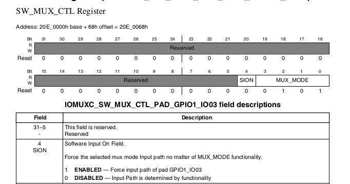
There are three registers, two of which are already defined in the macro. Looking at the manual, you can see that the muxRegister is a multiplex setting and the value set is muxMode, which is the same as the value set before.

So we don't need to look at the following functions
 *((volatile uint32_t *)muxRegister) =
        IOMUXC_SW_MUX_CTL_PAD_MUX_MODE(muxMode) | IOMUXC_SW_MUX_CTL_PAD_SION(inputOnfield);
We all know that he sets the mode of reuse to the reuse register. The latter or an inputOnfield is because the muxMode is only the last 3 bits, and the fourth has a sion bit, so set a 0 to turn it off.
configRegister is an electrical property setting

This parameter is not actually used in the function. The reason is described below
IOMUXC_SetPinConfig
Look at the source code for the function first
/*!
 * @brief Sets the IOMUXC pin configuration.
 * @note The previous five parameters can be filled with the pin function ID macros.
 *
 * This is an example to set pin configuration for IOMUXC_GPIO1_IO02_I2C1_SCL:
 * @code
 * IOMUXC_SetPinConfig(IOMUXC_GPIO1_IO02_I2C1_SCL, IOMUXC_SW_PAD_CTL_PAD_PUE_MASK | IOMUXC_SW_PAD_CTL_PAD_PUS(2U));
 * @endcode
 *
 * @param muxRegister  The pin mux register.
 * @param muxMode      The pin mux mode.
 * @param inputRegister The select input register.
 * @param inputDaisy   The input daisy.
 * @param configRegister  The config register.
 * @param configValue   The pin config value.
 */
static inline void IOMUXC_SetPinConfig(uint32_t muxRegister,
                                       uint32_t muxMode,
                                       uint32_t inputRegister,
                                       uint32_t inputDaisy,
                                       uint32_t configRegister,
                                       uint32_t configValue)
{
    if (configRegister)
    {
        *((volatile uint32_t *)configRegister) = configValue;
    }
}
We will find that the parameters of the function are the same as those of the reuse configuration mentioned earlier, and the first macro we pass in is the same as before. So both functions use a defined macro. The only difference is that the second value passed in (the sixth parameter of the function) is 0x10B0. Look at the method called in the function, which is also a parameter, passing the value of configValue to the configRegister register. It works the same as our previous assignment statements that configure electrical performance.
These two methods should be mastered skillfully, which is often used later when we make bare-metal drive. Use more to become skilled.