Timer introduction: the timer of 51 single chip microcomputer belongs to the internal resources of single chip microcomputer. The connection and operation of its circuit are completed inside the single chip microcomputer, which can replace the delay function occupying cpu resources.
My 51 single chip microcomputer is externally connected with an 11.0592MHZ external crystal oscillator. Let's calculate:
Calculation formula according to clock cycle
1 clock cycle = 1 / crystal oscillator cycle = 1/Fosc
Local clock cycle = 1/(11.05926M) (s)= 1/11.05926/1000000 (s) = 1/1105926 s
So my MCU adds 1 every 12 * (1 / 1105926) s. So it takes a total of time from 0 to 65535
12*(1/1105926)*65535=0.07110964s=71.10964ms
If you need to define a 10ms, set the initial value as x
(65535-x) * machine cycle = 0.01s
Then x=56319.
classification
51 MCU timer 0 has two one byte registers TH0 (high register) and TL0 (low register), which can store 65535 at most.
When the single chip microcomputer generates a pulse in each machine cycle, the counter will increase by one. When the count reaches the overflow value 65535, an interrupt signal will be generated, and the system captures the signal. This time period is the cycle.
The timer is controlled by two registers: working mode register TMOD and control register TCON.
Operating mode register TMOD
The working mode register TMOD is the working mode used to control timer 0 / 1 (mode 1: both TH0 and TL0 registers are used). To set the initial value, you only need to set M0 and M1 of TMOD, and all others can be set to 0. Timer 1 is not configured, and timer 0 is configured as follows
GATE=0
C/T=0:0 for timer and 1 for counter
TMOD=0x01

M1M0 # operating mode # description
00 # mode 1 # when the D5 position of TMOD is 0 and the D4 position is 1, it is the mode 1 of timer T1. This mode corresponds to a 16 bit timer. Registers TH1 and TL1 are the high 8 bits and low 8 bits of T1 initial value. The timing time is: (65536-T1 initial value) oscillation cycle 12
01 # mode 2 # when the D5 position of TMOD is 1 and the D4 position is 0, it is the mode 2 of timer T1. This mode corresponds to an 8-bit timer that can be loaded automatically. When the timer count is full (when the count overflows), it will automatically reload the content in TH1 into TL1. Then the maximum counting time of mode 2 is (initial value of 257-T1) oscillation period 12
TH0 and TL0
Since TH0 is the high octet and TL0 is the low octet (2 ^ 8 = 256), it is calculated
TH0=56319/256;
TL0=56319%256;
Using isp to calculate timer
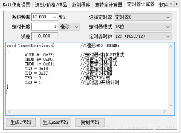
It should be noted that this version of MCU does not have AUXR register, so this line needs to be deleted and the assignment of ET0 and EA should be added. The overall code is as follows:
void Timer0Init(void)		//1ms @ 12.000MHz
{
	TMOD &= 0xF0;		//Set timer mode
	TMOD |= 0x01;		//Set timer mode
	TL0 = 0x18;		//Set timing initial value
	TH0 = 0xFC;		//Set timing initial value
	TF0 = 0;		//Clear TF0 flag
	TR0 = 1;		//Timer 0 starts timing
	ET0=1;//Enable timer 0 interrupt
	EA=1;//Open total interrupt
}
Control register TCON
TF0 = 0; // Clear the TF0 overflow interrupt flag. When it is added to 65536, TF0 will be set to 1
TR0 = 1; // Allow timer 0 to time
Example code (timer lighting)
#include "reg52.h" 			 // This file defines some special function registers of MCU

typedef unsigned int u16;	  //Declare and define data types
typedef unsigned char u8;

sbit led=P2^0;	 //Define P20 port as led


/*******************************************************************************
* Function name: Timer0Init
* Function function 		   :  Timer 0 initialization
* Input: None
* Output: None
*******************************************************************************/

void Timer0Init(void)		//1ms @ 12.000MHz
{
	TMOD &= 0xF0;		//Set timer mode
	TMOD |= 0x01;		//Set timer mode
	TL0 = 0x18;		//Set timing initial value
	TH0 = 0xFC;		//Set timing initial value
	TF0 = 0;		//Clear TF0 flag
	TR0 = 1;		//Timer 0 starts timing
	ET0=1;//Enable timer 0 interrupt
	EA=1;//Open total interrupt
}


/*******************************************************************************
* Function name: main
* Function function 		 :  Main function
* Input: None
* Output 	 :  nothing
*******************************************************************************/
void main()
{
	Timer0Init();  //Timer 0 initialization
	while(1);
}

/*******************************************************************************
* Function name: void Timer0() interrupt 1
* Function function 		   :  Timer 0 interrupt function
* Input: None
* Output: None
*******************************************************************************/
void Timer0() interrupt 1
{
	static u16 i;
	TH0=0XFC;	//Give the timer an initial value and set it for 1ms
	TL0=0X18;
	i++;
	if(i==1000)
	{
		i=0;
		led=~led;
	}
}