In the last section, we wrote a simple single led driver that can manipulate hardware.
In this section, we mainly show how to use multiple secondary device numbers to register multiple led drivers.
At the same time, we use the lower gpiolib library to use some special operations for gpio.
Here is the main code snippet.
Its function is to assign master device number subordinately, and use secondary device number 0 to control three LEDs at the same time, secondary device number 1, 2, 3 to control each stack separately.
#Include <linux/fs.h>/* Contains the file_operation structure*/
#Include <linux/init.h>/* Include module_init module_exit*/
#Include <linux/module.h>/* macros containing LICENSE*/
#include <asm/uaccess.h>
#include <linux/io.h>
#include <linux/device.h>
#include <linux/gpio.h>
#include <mach/gpio.h>
#include <asm/gpio.h>
#include <linux/gfp.h>
#include <plat/gpio-cfg.h>
#define GPJ0CON_PA 0xe0200240
static unsigned int major;
static struct class *leds_class;
static struct device *led_dev[4];
struct gpj0 {
unsigned int gpj0con;
unsigned int gpj0dat;
};
static struct gpj0* p_gpj0 = NULL;
static int leds_drv_open(struct inode *inode, struct file *file)
{
int minor = MINOR(inode->i_rdev); /* Get the sub-equipment number */
printk("leds_drv_open\n");
switch(minor)
{
case 0:
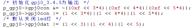
/* Initialize gpj0_3.4.5 as output */
p_gpj0->gpj0con &= ~((0xf << 3*4)|(0xf << 4*4)|(0xf << 5*4));
p_gpj0->gpj0con |= (1 << 3*4)|(1 << 4*4)|(1 << 5*4);
/* Turn off led lights by default */
p_gpj0->gpj0dat |= (1 << 3)|(1 << 4)|(1 << 5);
break;
case 1:
/* Initialize gpj0_3.4.5 as output */
p_gpj0->gpj0con &= ~(0xf << 3*4);
p_gpj0->gpj0con |= (1 << 3*4);
/* Turn off led lights by default */
p_gpj0->gpj0dat |= (1 << 3);
break;
case 2:
s3c_gpio_cfgpin(S5PV210_GPJ0(4), S3C_GPIO_SFN(1)); /* Output mode */
s3c_gpio_setpull(S5PV210_GPJ0(4), S3C_GPIO_PULL_UP); /* Pull up */
gpio_set_value(S5PV210_GPJ0(4),1); /* Set Close led */
break;
case 3:
s3c_gpio_cfgpin(S5PV210_GPJ0(5), S3C_GPIO_SFN(1));
s3c_gpio_setpull(S5PV210_GPJ0(5), S3C_GPIO_PULL_UP);
p_gpj0->gpj0dat |= (1 << 5);
break;
default:
break;
}
return 0;
}
static ssize_t leds_drv_write(struct file *file, const char __user * from, size_t len, loff_t *ppos)
{
char buf[10];
int ret, val;
int minor = MINOR(file->f_inode->i_rdev);
printk("leds_drv_write\n");
memset(buf, 0,10);
/* Copying User Space Data to Kernel Space */
ret = copy_from_user(buf, from, 3);
if(ret)
{
printk("copy_from_user fail\n");
}
if(strcmp("on", buf))
{
val = 1;
}
else
{
val = 0;
}
/* Setting the output of led according to parameters */
switch(minor)
{
case 0:
if(val)
p_gpj0->gpj0dat |= 7<<3;
else
p_gpj0->gpj0dat &= ~(7<<3);
break;
case 1:
gpio_set_value(S5PV210_GPJ0(3),val);
break;
case 2:
gpio_set_value(S5PV210_GPJ0(4),val);
break;
case 3:
gpio_set_value(S5PV210_GPJ0(5),val);
break;
default:
break;
}
return 0;
}
static const struct file_operations leds_drv_file_operation = {
.owner = THIS_MODULE,
.open = leds_drv_open,
.write = leds_drv_write,
};
static int __init leds_drv_init(void)
{
int i;
printk("leds_drv_init\n");
major = register_chrdev(0,"leds_drv",&leds_drv_file_operation);
/* Mapping io register */
p_gpj0 = ioremap(GPJ0CON_PA, 0x08);
if(NULL == p_gpj0)
{
printk("ioremap fail\n");
return -1;
}
/* Create a class */
leds_class = class_create(THIS_MODULE, "leds_class");
if(!leds_class)
{
if (IS_ERR(leds_class))
return PTR_ERR(leds_class);
}
/* Create devices that belong to this class */
led_dev[0] = device_create(leds_class,NULL,MKDEV(major, 0), NULL, "leds");
if (IS_ERR(led_dev))
return PTR_ERR(led_dev);
/* Create three other devices */
for(i = 1; i < 4; i++)
{
led_dev[i] = device_create(leds_class,NULL,MKDEV(major, i), NULL, "led%d",i);
if (IS_ERR(led_dev))
return PTR_ERR(led_dev);
}
if(gpio_request(S5PV210_GPJ0(3), "led1-gpj0-3"))
{
return -1;
}
if(gpio_request(S5PV210_GPJ0(4), "led2-gpj0-4"))
{
return -1;
}
if(gpio_request(S5PV210_GPJ0(5), "led3-gpj0-5"))
{
return -1;
}
return 0;
}
static void __exit leds_drv_exit(void)
{
int i;
unregister_chrdev(major,"leds_drv");
printk("leds_drv_exit\n");
/* Unmapping after use */
iounmap(p_gpj0);
/* Cancellation of equipment in the class */
for(i = 0; i < 4; i++)
{
device_unregister(led_dev[i]);
}
/* Logoff class */
class_destroy(leds_class);
gpio_free(S5PV210_GPJ0(3));
gpio_free(S5PV210_GPJ0(4));
gpio_free(S5PV210_GPJ0(5));
}
module_init(leds_drv_init);
module_exit(leds_drv_exit);
MODULE_LICENSE("GPL");
Starting with the registration function
    /* Create three other devices */
    for(i = 1; i < 4; i++)
    {
        led_dev[i] = device_create(leds_class,NULL,MKDEV(major, i), NULL, "led%d",i);
        if (IS_ERR(led_dev))
            return PTR_ERR(led_dev);
    }
The other parts of the registration function have been analyzed, and the starting one is very similar. Even with the same primary device number, different secondary device numbers register multiple devices (the name of the secondary device is printed in a format similar to printf).
Here we use the gpiolib library, we mainly talk about the gpiolib library.
ioremap in the first two sections can map all registers (arm s), including gpio registers, of course.
Our use is to manipulate it by writing memory in the mapped address space.
There's nothing wrong with arm, but there may be problems with other architectures.
The system provides a more general method of manipulating registers.
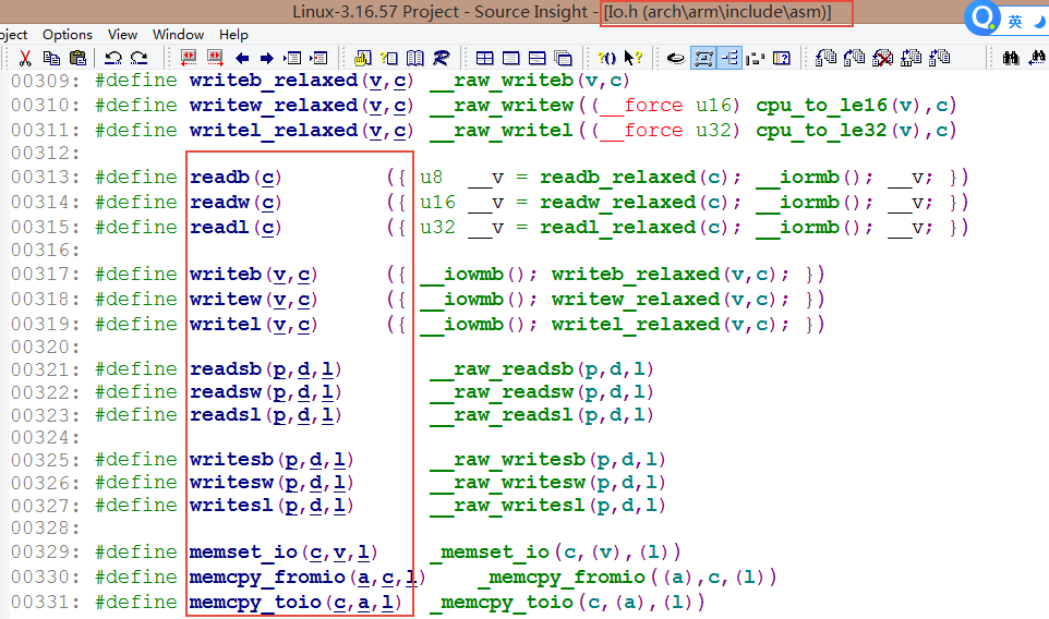
Usually we manipulate registers. A more general way of writing is to use the interface provided above to manipulate registers. (Later driver code will use this approach)
Note: This procedure for using registers
1.ioremap mapping register
2.readl/writel and other read-write registers
3. The iounmap Release Map (Page Table) Register after the end of use
Of course, here we use gpio registers, which are one kind of registers.
Because of its particularity, the linux kernel has made a special library called gpiolib.
Its particularity: because gpio can be reused by multiple peripherals (other peripherals such as i2c, lcd, etc.), if one peripheral is in use, the other will also be used, which will lead to disordered timing, so we must wait until the previous one is used before the other can be used, so that the driver can work perfectly.
For all the reasons mentioned above, the simplest way is to apply for an IO before using it, just like other resources. Otherwise, sleep awaits the arrival of the resource or the registration of the driver fails.
On gpiolib:
1. Kernel developers implement common interfaces (no actual operations)
2. Specific details of each platform or specific cpu are submitted to the kernel developer (referring to the original chip factory)
The following are the functions for applying and releasing gpio in the kernel
driver/gpio/gpiolib.c
int gpio_request(unsigned gpio, const char *label); /* apply for a gpio*/
Int gpio_request_one (unsigned gpio, unsigned long flags, const char*label); /* apply for a GPIO and initialize the GPIO with flag*/
int gpio_request_array(const struct gpio *array, size_t num); /* apply for multiple gpio, which calls gpio_request_one*/


Applying for a gpio start is simple. A table bitmap [array] is maintained in gpiolib. Each bit in the table represents an io. If this IO is not useful, then this one
 bit is 0, if used, marked as 1. When the request is 0, it can be requested, and when it is 1, the request will fail.


void gpio_free(unsigned gpio);
void gpio_free_array(const struct gpio *array, size_t num);
There are applications, of course, must be released, release is also very simple, the response position in the bitmap table is 0.
You can see that there is a parameter of GPIO in the above parameters, which represents the label of gpio, that is, the system will mark each GPIO with a number.
label denotes the name of the gpio (optionally, for ease of viewing usage)
When multiple requests and releases are made, the incoming is the gpio structure, and it is also the combination package of the first few parameters that we call it.
/**
 * struct gpio - a structure describing a GPIO with configuration
 * @gpio:	the GPIO number
 * @flags:	GPIO configuration as specified by GPIOF_*
 * @label:	a literal description string of this GPIO
 */
struct gpio {
	unsigned	gpio;
	unsigned long	flags;
	const char	*label;
};
Next, let's look at the specific chip gpiolib library's label assignment for gpio
arch/arm/mach-s5pv210/include/mach/gpio.h
Number of gpio in each group
/* GPIO bank sizes */
#define S5PV210_GPIO_A0_NR	(8)
#define S5PV210_GPIO_A1_NR	(4)
#define S5PV210_GPIO_B_NR	(8)
#define S5PV210_GPIO_C0_NR	(5)
..........
#define S5PV210_GPIO_J1_NR	(6)
#define S5PV210_GPIO_J2_NR	(8)
#define S5PV210_GPIO_J3_NR	(8)
#define S5PV210_GPIO_J4_NR	(5)

#define S5PV210_GPIO_MP01_NR	(8)
#define S5PV210_GPIO_MP02_NR	(4)
#define S5PV210_GPIO_MP03_NR	(8)
#define S5PV210_GPIO_MP04_NR	(8)
#define S5PV210_GPIO_MP05_NR	(8)
Initial labeling of each group of gpio
#define S5PV210_GPIO_NEXT(__gpio) \
((__gpio##_START) + (__gpio##_NR) + CONFIG_S3C_GPIO_SPACE + 1)
enum s5p_gpio_number {
S5PV210_GPIO_A0_START = 0,
S5PV210_GPIO_A1_START = S5PV210_GPIO_NEXT(S5PV210_GPIO_A0),
S5PV210_GPIO_B_START = S5PV210_GPIO_NEXT(S5PV210_GPIO_A1),
S5PV210_GPIO_C0_START = S5PV210_GPIO_NEXT(S5PV210_GPIO_B),
.............
S5PV210_GPIO_MP03_START = S5PV210_GPIO_NEXT(S5PV210_GPIO_MP02),
S5PV210_GPIO_MP04_START = S5PV210_GPIO_NEXT(S5PV210_GPIO_MP03),
S5PV210_GPIO_MP05_START = S5PV210_GPIO_NEXT(S5PV210_GPIO_MP04),
};
//We take GPIOB as an example to analyze.
S5PV210_GPIO_B_START = S5PV210_GPIO_NEXT(S5PV210_GPIO_A1)
#define S5PV210_GPIO_NEXT(__gpio) \
((__gpio##_START) + (__gpio##_NR) + CONFIG_S3C_GPIO_SPACE + 1)
S5PV210_GPIO_NEXT(S5PV210_GPIO_A1)
((__gpio##_START) + (__gpio##_NR) + CONFIG_S3C_GPIO_SPACE + 1)
S5PV210_GPIO_A1_START + S5PV210_GPIO_A1_NR + CONFIG_S3C_GPIO_SPACE + 1
.....
((0 + 8 + CONFIG_S3C_GPIO_SPACE + 1) + 4 + CONFIG_S3C_GPIO_SPACE + 1)
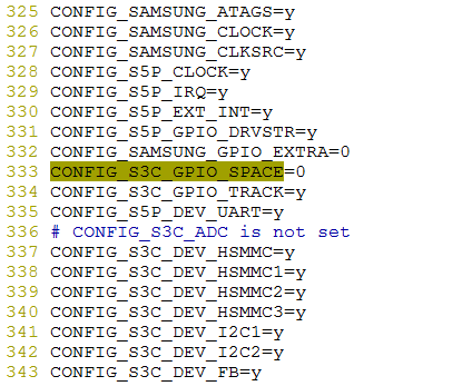
//The CONFIG_S3C_GPIO_SPACE is available in the. config file.
//It can be found that there is an additional one between each group as an interval.
Each gpio number = group start number + intra-group migration
/* S5PV210 GPIO number definitions */
#define S5PV210_GPA0(_nr)	(S5PV210_GPIO_A0_START + (_nr))
#define S5PV210_GPA1(_nr)	(S5PV210_GPIO_A1_START + (_nr))
#define S5PV210_GPB(_nr)	(S5PV210_GPIO_B_START + (_nr))
#define S5PV210_GPC0(_nr)	(S5PV210_GPIO_C0_START + (_nr))
#define S5PV210_GPC1(_nr)	(S5PV210_GPIO_C1_START + (_nr))
.......
#define S5PV210_MP02(_nr)	(S5PV210_GPIO_MP02_START + (_nr))
#define S5PV210_MP03(_nr)	(S5PV210_GPIO_MP03_START + (_nr))
#define S5PV210_MP04(_nr)	(S5PV210_GPIO_MP04_START + (_nr))
#define S5PV210_MP05(_nr)	(S5PV210_GPIO_MP05_START + (_nr))
Implementation of gpiolib Library
1. Implementing the following structure
/**
 * struct gpio_chip - abstract a GPIO controller
 * @label: for diagnostics
 * @dev: optional device providing the GPIOs
 * @owner: helps prevent removal of modules exporting active GPIOs
 * @list: links gpio_chips together for traversal
 * @request: optional hook for chip-specific activation, such as
 *	enabling module power and clock; may sleep
 * @free: optional hook for chip-specific deactivation, such as
 *	disabling module power and clock; may sleep
 * @get_direction: returns direction for signal "offset", 0=out, 1=in,
 *	(same as GPIOF_DIR_XXX), or negative error
 * @direction_input: configures signal "offset" as input, or returns error
 * @direction_output: configures signal "offset" as output, or returns error
 * @get: returns value for signal "offset"; for output signals this
 *	returns either the value actually sensed, or zero
 * @set: assigns output value for signal "offset"
 * @set_debounce: optional hook for setting debounce time for specified gpio in
 *      interrupt triggered gpio chips
 * @to_irq: optional hook supporting non-static gpio_to_irq() mappings;
 *	implementation may not sleep
 * @dbg_show: optional routine to show contents in debugfs; default code
 *	will be used when this is omitted, but custom code can show extra
 *	state (such as pullup/pulldown configuration).
 * @base: identifies the first GPIO number handled by this chip; or, if
 *	negative during registration, requests dynamic ID allocation.
 * @ngpio: the number of GPIOs handled by this controller; the last GPIO
 *	handled is (base + ngpio - 1).
 * @desc: array of ngpio descriptors. Private.
 * @names: if set, must be an array of strings to use as alternative
 *      names for the GPIOs in this chip. Any entry in the array
 *      may be NULL if there is no alias for the GPIO, however the
 *      array must be @ngpio entries long.  A name can include a single printk
 *      format specifier for an unsigned int.  It is substituted by the actual
 *      number of the gpio.
 * @can_sleep: flag must be set iff get()/set() methods sleep, as they
 *	must while accessing GPIO expander chips over I2C or SPI. This
 *	implies that if the chip supports IRQs, these IRQs need to be threaded
 *	as the chip access may sleep when e.g. reading out the IRQ status
 *	registers.
 * @exported: flags if the gpiochip is exported for use from sysfs. Private.
 *
 * A gpio_chip can help platforms abstract various sources of GPIOs so
 * they can all be accessed through a common programing interface.
 * Example sources would be SOC controllers, FPGAs, multifunction
 * chips, dedicated GPIO expanders, and so on.
 *
 * Each chip controls a number of signals, identified in method calls
 * by "offset" values in the range 0..(@ngpio - 1).  When those signals
 * are referenced through calls like gpio_get_value(gpio), the offset
 * is calculated by subtracting @base from the gpio number.
 */
struct gpio_chip {
	const char		*label;
	struct device		*dev;
	struct module		*owner;
	struct list_head        list;

	int			(*request)(struct gpio_chip *chip,
						unsigned offset);
	void			(*free)(struct gpio_chip *chip,
						unsigned offset);
	int			(*get_direction)(struct gpio_chip *chip,
						unsigned offset);
	int			(*direction_input)(struct gpio_chip *chip,
						unsigned offset);
	int			(*direction_output)(struct gpio_chip *chip,
						unsigned offset, int value);
	int			(*get)(struct gpio_chip *chip,
						unsigned offset);
	void			(*set)(struct gpio_chip *chip,
						unsigned offset, int value);
	int			(*set_debounce)(struct gpio_chip *chip,
						unsigned offset,
						unsigned debounce);

	int			(*to_irq)(struct gpio_chip *chip,
						unsigned offset);

	void			(*dbg_show)(struct seq_file *s,
						struct gpio_chip *chip);
	int			base;
	u16			ngpio;
	struct gpio_desc	*desc;
	const char		*const *names;
	bool			can_sleep;
	bool			exported;

#ifdef CONFIG_GPIOLIB_IRQCHIP
	/*
	 * With CONFIG_GPIO_IRQCHIP we get an irqchip inside the gpiolib
	 * to handle IRQs for most practical cases.
	 */
	struct irq_chip		*irqchip;
	struct irq_domain	*irqdomain;
	unsigned int		irq_base;
	irq_flow_handler_t	irq_handler;
	unsigned int		irq_default_type;
#endif

#if defined(CONFIG_OF_GPIO)
	/*
	 * If CONFIG_OF is enabled, then all GPIO controllers described in the
	 * device tree automatically may have an OF translation
	 */
	struct device_node *of_node;
	int of_gpio_n_cells;
	int (*of_xlate)(struct gpio_chip *gc,
			const struct of_phandle_args *gpiospec, u32 *flags);
#endif
#ifdef CONFIG_PINCTRL
	/*
	 * If CONFIG_PINCTRL is enabled, then gpio controllers can optionally
	 * describe the actual pin range which they serve in an SoC. This
	 * information would be used by pinctrl subsystem to configure
	 * corresponding pins for gpio usage.
	 */
	struct list_head pin_ranges;
#endif
};
2. Interfaces provided within
/* These are commonly used directly at the io level */
static inline int gpio_get_value(unsigned int gpio)
{
	return __gpio_get_value(gpio);
}

static inline void gpio_set_value(unsigned int gpio, int value)
{
	__gpio_set_value(gpio, value);
}

static inline int gpio_cansleep(unsigned int gpio)
{
	return __gpio_cansleep(gpio);
}

static inline int gpio_to_irq(unsigned int gpio)
{
	return __gpio_to_irq(gpio);
}

static inline int irq_to_gpio(unsigned int irq)
{
	return -EINVAL;
}


/* CONFIG_GPIOLIB: bindings for managed devices that want to request gpios */

struct device;
/* The following are used in specific devices, which also call the above, but one more step is to automatically release the application io when uninstalling the device. */
int devm_gpio_request(struct device *dev, unsigned gpio, const char *label);
int devm_gpio_request_one(struct device *dev, unsigned gpio,
			  unsigned long flags, const char *label);
void devm_gpio_free(struct device *dev, unsigned int gpio);


//Examples:
1.gpio_set_value
static inline void gpio_set_value(unsigned int gpio, int value)
{
	__gpio_set_value(gpio, value);
}

static inline void __gpio_set_value(unsigned gpio, int value)
{
	return gpiod_set_raw_value(gpio_to_desc(gpio), value);
}
void gpiod_set_raw_value(struct gpio_desc *desc, int value)
{
	if (!desc)
		return;
	/* Should be using gpiod_set_value_cansleep() */
	WARN_ON(desc->chip->can_sleep);
	_gpiod_set_raw_value(desc, value);
}

static void _gpiod_set_raw_value(struct gpio_desc *desc, bool value)
{
	struct gpio_chip	*chip;

	chip = desc->chip;
	trace_gpio_value(desc_to_gpio(desc), 0, value);
	if (test_bit(FLAG_OPEN_DRAIN, &desc->flags))
		_gpio_set_open_drain_value(desc, value);
	else if (test_bit(FLAG_OPEN_SOURCE, &desc->flags))
		_gpio_set_open_source_value(desc, value);
	else
		chip->set(chip, gpio_chip_hwgpio(desc), value);    /* Final call here (specific hardware vendor implementation) */
}
2.devm_gpio_request
int devm_gpio_request(struct device *dev, unsigned gpio, const char *label)
{
	unsigned *dr;
	int rc;

    /* Apply space, etc., and bind the logout function, which will be called when the device is uninstalled in the future, releasing the io of the application in the function of the uninstall device. */
	dr = devres_alloc(devm_gpio_release, sizeof(unsigned), GFP_KERNEL);
	if (!dr)
		return -ENOMEM;

	rc = gpio_request(gpio, label);    /* Application for io */
	if (rc) {
		devres_free(dr);
		return rc;
	}

	*dr = gpio;
	devres_add(dev, dr);               /* Registered resources */

	return 0;
}
3. Manufacturer's Interface and Kernel Binding (Samsung Platform as an example)
/* TODO: cleanup soc_is_* */
static __init int samsung_gpiolib_init(void)
{
	struct samsung_gpio_chip *chip;
	int i, nr_chips;
	int group = 0;

	/*
	 * Currently there are two drivers that can provide GPIO support for
	 * Samsung SoCs. For device tree enabled platforms, the new
	 * pinctrl-samsung driver is used, providing both GPIO and pin control
	 * interfaces. For legacy (non-DT) platforms this driver is used.
	 */
	if (of_have_populated_dt())
		return -ENODEV;

    /* General Configuration of Platform */
	samsung_gpiolib_set_cfg(samsung_gpio_cfgs, ARRAY_SIZE(samsung_gpio_cfgs));

	if (soc_is_s3c24xx()) {
		......
	} else if (soc_is_s3c64xx()) {
		......
	} else if (soc_is_s5p6440()) {
		......
	} else if (soc_is_s5p6450()) {
		......
	} else if (soc_is_s5pc100()) {
		......
	} else if (soc_is_s5pv210()) {    /* We're only looking at this. */
		group = 0;
		chip = s5pv210_gpios_4bit;    /* gpio Resource table, see the following analysis */
		nr_chips = ARRAY_SIZE(s5pv210_gpios_4bit);

        /* General parameters in filling tables */
		for (i = 0; i < nr_chips; i++, chip++) {
			if (!chip->config) {
				chip->config = &samsung_gpio_cfgs[3];
				chip->group = group++;
			}
		}
        /* The following functions are important: bind vendor's and kernel's generic */
		samsung_gpiolib_add_4bit_chips(s5pv210_gpios_4bit, nr_chips, S5P_VA_GPIO);
#if defined(CONFIG_CPU_S5PV210) && defined(CONFIG_S5P_GPIO_INT)
		s5p_register_gpioint_bank(IRQ_GPIOINT, 0, S5P_GPIOINT_GROUP_MAXNR);
#endif
	} else {
		WARN(1, "Unknown SoC in gpio-samsung, no GPIOs added\n");
		return -ENODEV;
	}

	return 0;
}
core_initcall(samsung_gpiolib_init);    /* core_initcall It was the first one to be called, recall module_init */

struct samsung_gpio_chip {
	struct gpio_chip	chip;           /* Universal Kernel */
	struct samsung_gpio_cfg	*config;    /* Other Samsung packages themselves on the basis of the kernel */
	struct samsung_gpio_pm	*pm;
	void __iomem		*base;
	int			irq_base;
	int			group;
	spinlock_t		 lock;
#ifdef CONFIG_PM
	u32			pm_save[4];
#endif
	u32			bitmap_gpio_int;
};

/* We used all the GPIO groups we defined earlier, and a table containing all the gpios. If there is any gpios at the time of application, we can check this table. */
static struct samsung_gpio_chip s5pv210_gpios_4bit[] = {
#ifdef CONFIG_CPU_S5PV210
	{
		.chip	= {
			.base	= S5PV210_GPA0(0),
			.ngpio	= S5PV210_GPIO_A0_NR,
			.label	= "GPA0",
		},
	}, {
		.chip	= {
			.base	= S5PV210_GPA1(0),
			.ngpio	= S5PV210_GPIO_A1_NR,
			.label	= "GPA1",
		},
	.................
	}, {
		.base	= (S5P_VA_GPIO + 0xC60),
		.irq_base = IRQ_EINT(24),
		.chip	= {
			.base	= S5PV210_GPH3(0),
			.ngpio	= S5PV210_GPIO_H3_NR,
			.label	= "GPH3",
			.to_irq = samsung_gpiolib_to_irq,
		},
	},
#endif
};
samsung_gpiolib_add_4bit_chips(s5pv210_gpios_4bit, nr_chips, S5P_VA_GPIO);
Parametric 1: Table address
 Parametric 2: Number of elements in the table
 Parametric 3: Base address of virtual address of GPIO register in kernel space (3-4 G)
static void __init samsung_gpiolib_add_4bit_chips(struct samsung_gpio_chip *chip,
						  int nr_chips, void __iomem *base)
{
	int i;

	for (i = 0 ; i < nr_chips; i++, chip++) {
		chip->chip.direction_input = samsung_gpiolib_4bit_input;   /* Binding a generic operating interface, 4bit means configuring registers to configure various modes using 4bit */
		chip->chip.direction_output = samsung_gpiolib_4bit_output;    /* Binding Universal Operational Interface */

		if (!chip->config)
			chip->config = &samsung_gpio_cfgs[2];
		if (!chip->pm)
			chip->pm = __gpio_pm(&samsung_gpio_pm_4bit);
		if ((base != NULL) && (chip->base == NULL))
			chip->base = base + ((i) * 0x20);    /* Each interface takes up 0 x 20 bytes of registers. It is convenient to map the addresses of each set of registers directly in the kernel space. */

		chip->bitmap_gpio_int = 0;

		samsung_gpiolib_add(chip);    /* Continue to add operation interfaces */
	}
}

static void __init samsung_gpiolib_add(struct samsung_gpio_chip *chip)
{
	struct gpio_chip *gc = &chip->chip;
	int ret;

	BUG_ON(!chip->base);
	BUG_ON(!gc->label);
	BUG_ON(!gc->ngpio);

	spin_lock_init(&chip->lock);

	if (!gc->direction_input)        /* The 4 bits above have been added, so we won't add 2 bits here. */
		gc->direction_input = samsung_gpiolib_2bit_input;
	if (!gc->direction_output)
		gc->direction_output = samsung_gpiolib_2bit_output;
	if (!gc->set)
		gc->set = samsung_gpiolib_set;    /* Setting up high and low levels */
	if (!gc->get)
		gc->get = samsung_gpiolib_get;    /* Get the current level */

#ifdef CONFIG_PM
	if (chip->pm != NULL) {
		if (!chip->pm->save || !chip->pm->resume)
			pr_err("gpio: %s has missing PM functions\n",
			       gc->label);
	} else
		pr_err("gpio: %s has no PM function\n", gc->label);
#endif

	/* gpiochip_add() prints own failure message on error. */
	ret = gpiochip_add(gc);        /* Add this group to the list */
	if (ret >= 0)
		s3c_gpiolib_track(chip);
}
4. The previous function bindings are very concise. The only thing to note is that the parameter S5P_VA_GPIO added above can see that it is already a VA, that is, a virtual address.
arch/arm/plat-samsung/include/plat/map-s5p.h
#define S3C_ADDR_BASE	0xF6000000

#ifndef __ASSEMBLY__
#define S3C_ADDR(x)	((void __iomem __force *)S3C_ADDR_BASE + (x))
#else
#define S3C_ADDR(x)	(S3C_ADDR_BASE + (x))
#endif

#define S3C_VA_IRQ	S3C_ADDR(0x00000000)	/* irq controller(s) */
#define S3C_VA_SYS	S3C_ADDR(0x00100000)	/* system control */
#define S3C_VA_MEM	S3C_ADDR(0x00200000)	/* memory control */
.......
#define S5P_VA_GPIO		S3C_ADDR(0x02200000)

//You can see that the virtual address of our GPIO register is mapped to 0xF8200000, which is obviously not a physical address, so it must be a virtual address.
5. Static Mapping of Resources
arch/arm/mach-s5pv210/common.c
/* Initial IO mappings,Detailed parameters for all register resources va,pa page number, etc. */
static struct map_desc s5pv210_iodesc[] __initdata = {
{
.virtual = (unsigned long)S5P_VA_CHIPID,
.pfn = __phys_to_pfn(S5PV210_PA_CHIPID),
.length = SZ_4K,
.type = MT_DEVICE,
}, {
.virtual = (unsigned long)S3C_VA_SYS,
.pfn = __phys_to_pfn(S5PV210_PA_SYSCON),
.length = SZ_64K,
.type = MT_DEVICE,
}, {
.virtual = (unsigned long)S3C_VA_TIMER,
.pfn = __phys_to_pfn(S5PV210_PA_TIMER),
.length = SZ_16K,
.type = MT_DEVICE,
}, {
.virtual = (unsigned long)S3C_VA_WATCHDOG,
.pfn = __phys_to_pfn(S5PV210_PA_WATCHDOG),
.length = SZ_4K,
.type = MT_DEVICE,
}, {
.virtual = (unsigned long)S5P_VA_SROMC,
.pfn = __phys_to_pfn(S5PV210_PA_SROMC),
.length = SZ_4K,
.type = MT_DEVICE,
}, {
.virtual = (unsigned long)S5P_VA_SYSTIMER,
.pfn = __phys_to_pfn(S5PV210_PA_SYSTIMER),
.length = SZ_4K,
.type = MT_DEVICE,
}, {
.virtual = (unsigned long)S5P_VA_GPIO,
.pfn = __phys_to_pfn(S5PV210_PA_GPIO),
.length = SZ_4K,
.type = MT_DEVICE,
}, {
.virtual = (unsigned long)VA_VIC0,
.pfn = __phys_to_pfn(S5PV210_PA_VIC0),
.length = SZ_16K,
.type = MT_DEVICE,
}, {
.virtual = (unsigned long)VA_VIC1,
.pfn = __phys_to_pfn(S5PV210_PA_VIC1),
.length = SZ_16K,
.type = MT_DEVICE,
}, {
.virtual = (unsigned long)VA_VIC2,
.pfn = __phys_to_pfn(S5PV210_PA_VIC2),
.length = SZ_16K,
.type = MT_DEVICE,
}, {
.virtual = (unsigned long)VA_VIC3,
.pfn = __phys_to_pfn(S5PV210_PA_VIC3),
.length = SZ_16K,
.type = MT_DEVICE,
}, {
.virtual = (unsigned long)S3C_VA_UART,
.pfn = __phys_to_pfn(S3C_PA_UART),
.length = SZ_512K,
.type = MT_DEVICE,
}, {
.virtual = (unsigned long)S5P_VA_DMC0,
.pfn = __phys_to_pfn(S5PV210_PA_DMC0),
.length = SZ_4K,
.type = MT_DEVICE,
}, {
.virtual = (unsigned long)S5P_VA_DMC1,
.pfn = __phys_to_pfn(S5PV210_PA_DMC1),
.length = SZ_4K,
.type = MT_DEVICE,
}, {
.virtual = (unsigned long)S3C_VA_USB_HSPHY,
.pfn =__phys_to_pfn(S5PV210_PA_HSPHY),
.length = SZ_4K,
.type = MT_DEVICE,
}
};
/*
* s5pv210_map_io
*
* register the standard cpu IO areas
*/
void __init s5pv210_init_io(struct map_desc *mach_desc, int size)
{
/* initialize the io descriptors we need for initialization */
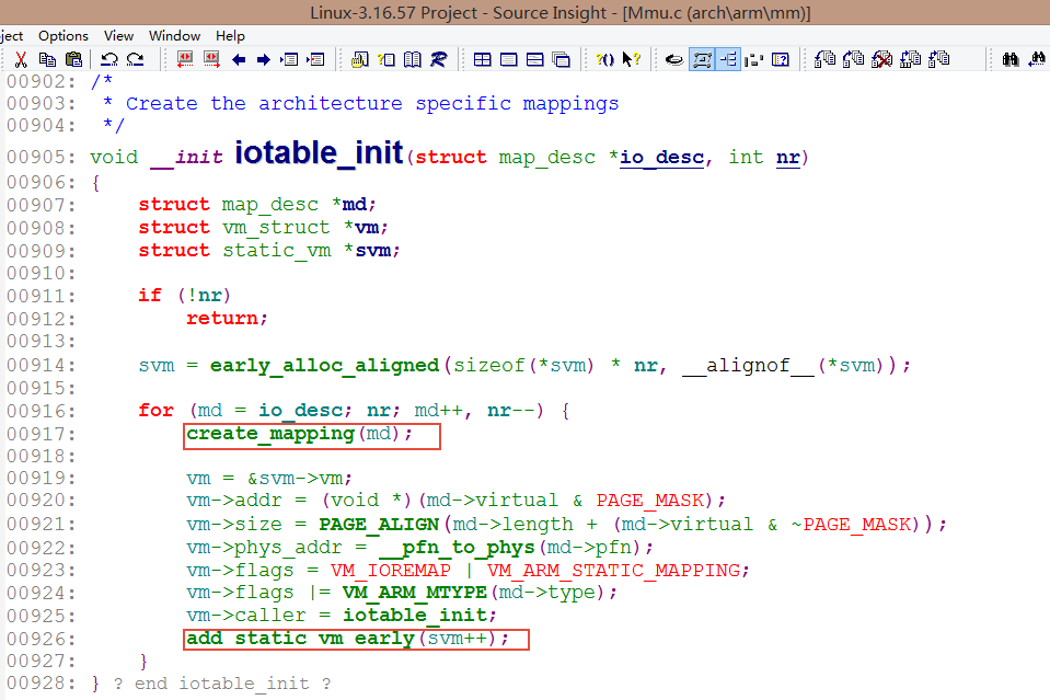
iotable_init(s5pv210_iodesc, ARRAY_SIZE(s5pv210_iodesc)); /* Initialization, registering the contents of the table above */
if (mach_desc)
iotable_init(mach_desc, size);
/* detect cpu id and rev. */
s5p_init_cpu(S5P_VA_CHIPID);
s3c_init_cpu(samsung_cpu_id, cpu_ids, ARRAY_SIZE(cpu_ids));
samsung_pwm_set_platdata(&s5pv210_pwm_variant);
}
In mmu.c, this function must be related to virtual memory mapping. Let's not start here. There's time for a special topic later.
There are two main things to do: 1. Create a page table; 2. Fill in the page table entries created above with parameters such as page number, virtual address, mapping type and so on.
Explain:
1. Dynamic mapping and static mapping do not conflict, they can be both (the default start-up phase has been static mapping, we used the system's gpiolib static, but also their own dynamic ioremap mapping two registers)
2. Static mapping of all registers in level 4 page tables takes up a part (start first, take up the front part), and the virtual address of the mapping takes up a part of the address in a kernel space (our define S3C_ADDR_BASE 0xF6000000, to define S5P_VA_GIC_DIST S3C_ADDR(0x02820000) +offset), while the page table in the dynamic mapping in the later driver will be static. At the same time, the virtual address of the state mapping is also backward.
3. In a process, the same (group) register can be ioremap many times, each time ioremap, it will create a new page table for it, that is, there will be different virtual addresses. But these virtual addresses are all mapped to the same physical address, so no matter which ioremap returns the virtual address, the final operation can be that physical address.
Where the above program is not perfect:
1. Error handling is not perfect, or even no error handling.
2. Program dynamic mapping and static mapping make a mess.
The next section improves:
1. Error handling
2. All static mapping interfaces provided by gpiolib are used.