Reprinted from Feng Lele's "Unity Shader Essentials"
Getting Depth and Normal Texture
Although the code for obtaining depth and normal textures in Unity is very simple, we need to understand the implementation behind them first.
Depth texture is actually a rendering texture, but the pixel value stored in it is not a color value but a high-precision depth value. Because it is stored in a texture, the range of depth values in a depth texture is [0,1], and is usually non-linear. So where do these depth values come from? Generally speaking, these depth values are derived from the normalized device coordinates (NDC) obtained by vertex transformation. If a model wants to be drawn on the screen, it needs to transform its vertices from model space to homogeneous clipping coordinate system, which is obtained by multiplying MVP transformation matrix in vertex shader. In the last step of transformation, we need to use a projection matrix to transform vertices. When we use perspective projection type camera, the projection matrix is non-linear.
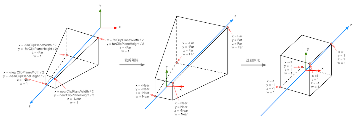
The following figure shows the transformation process of perspective projection to vertices in Unity given previously. The left-most figure of the following figure shows the results of the transformation before the projection transformation, i.e., the results of the viewing cone in the observation space and the corresponding vertex positions. The middle figure shows the transformation results after the application of perspective clipping matrix, i.e. the vertex transformation results output in the vertex shader stage, and the right-most figure shows the entry of the underlying hardware. Normalized equipment coordinates obtained by perspective division are performed. It should be noted that the projection process here is based on Unity's assumption of the coordinate system. That is to say, we aim at the case where the observation space is a right-handed coordinate system, where column matrices are multiplied on the right side of the matrix, and the z component range will be between [-1,1] after transformation to NDC. Similar to DirectX In such a graphical interface, the range of z component after transformation will be between [0,1].
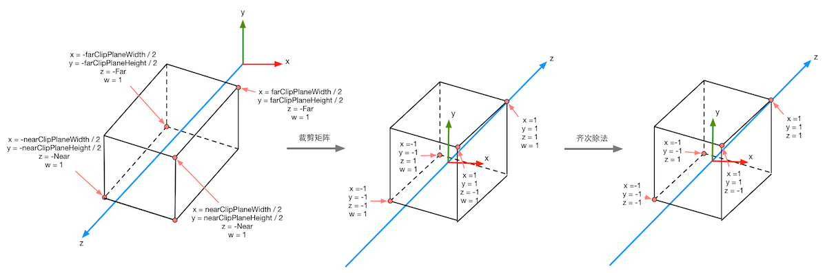
The following figure shows the process of projection transformation when orthogonal cameras are used again. The same transformation results in a cube with a range of [-1,1]. The transformation matrix used in orthogonal projection is linear.
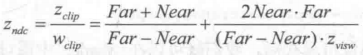
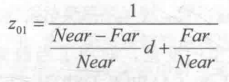
After the NDC is obtained, the pixel values in the depth texture can be easily calculated. These depth values correspond to the z component of the vertex coordinates in the NDC. Since the z component in NDC is in the range of [-1,1], in order to store these values in an image, we need to map them using the following formula:
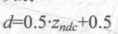
Among them, d corresponds to the pixel value in depth texture and Z(ndc) corresponds to the value of z component in NDC coordinates.
In Unity, the depth texture can be directly derived from the real depth cache, or it can be rendered by a single Pass, depending on the rendering path and hardware used. Generally speaking, when using delayed rendering paths, deep textures are naturally accessible, because delayed rendering renders these information into G-buffer. When deep caching is not available directly, the depth and normal texture are rendered by a single Pass. Specifically, Unity will use shader replacement technology to select objects of Opaque rendering type and determine whether the rendering queue they use is less than 2500. If conditions are met, it will be rendered into depth and normal texture. Therefore, in order for objects to appear in depth and normal texture, it is necessary to set the correct RenderType in Shader. Label.
In Unity, we can choose to have a camera generate a depth texture or a depth + normal texture. When rendering the former, i.e. only a single depth texture is needed, Unity will directly obtain the depth cache or select the opaque object needed according to the previous shader replacement technology, and use Pass (that is, LightMode is set to ShadowCaster Pass) to get the depth texture. If Shader does not contain such a Pass, the object will not appear in the depth texture (of course, it cannot cast shadows on other objects). The accuracy of depth texture is usually 24 or 16 bits, depending on the accuracy of depth caching used. If you choose to generate a depth + normal texture, Unity will create a 32-bit (texture) with the same resolution as the screen, in which the normal information in the viewing space will be encoded into the R and G channels of the texture, and the depth information will be encoded into the B and A channels. Normal information can be easily obtained in delayed rendering. Unity only needs to merge depth and normal cache. In forward rendering, the normal cache is not created by default, so the Unity underlying layer uses a separate Pass to render the entire scene again. This Pass is included in a Unity built-in Unity In Shader, we can find this Pass for rendering depth and normal information in the built-in builtin_shaders-xxx/DefaultResources/Camera-DepthNormalTexture.shader file.
In Unity, it's very easy to get deep texture. We just need to tell Unity, "Give me the deep texture!" Then you can directly access specific texture attributes in Shader. This process of communicating with Unity is accomplished by setting the camera's depthTextureMode in the script. For example, we can get the deep texture through the following code:
Once the camera mode above is set, we can access it in Shader by declaring the _CameraDepthTexture variable. This process is very simple, but we need to know that behind two lines of code, Unity has done a lot of work for us.camera.depthTextureMode = DepthTextureMode.Depth;
Similarly, if we want to get the depth + normal texture, we only need to set it in the code as follows:
It is then accessed in Shader by declaring the _CameraDepthNormalsTexture variable.camera.depthTextureMode = DepthTextureMode.DepthNormals;
We can also combine these modes so that a camera can produce a depth and depth + normal texture at the same time:
In Unity 5, we can also see whether the current camera needs to render depth or depth + normal texture on the Camera's Camera component. When we access the depth texture _CameraDepthTexture in Shader, we can use the texture coordinates of the current pixel to sample it. In most cases, we can use tex2D function to sample directly, but on some platforms, we need some special processing. Unity provides us with a unified macro SAMPLE_DEPTH_TEXTURE to deal with these problems caused by platform differences. We only need to use SAMPLE_DEPTH_TEXTURE macro to sample depth texture in Shader, for example:camera.depthTextureMode |= DepthTextureMode.Depth; camera.depthTextureMode |= DepthTextureMode.DepthNormals;
Among them, i.uv is a float2 variable, which corresponds to the texture coordinates of the current pixel. Similar macros include SAMPLE_DEPTH_TEXTURE_PROJ and SAMPLE_DEPTH_TEXTURE_LOD. SAMPLE_DEPTH_TEXTURE_PROJ The macro also accepts two parameters - depth texture and a float3 or float4 texture coordinate. It uses functions such as tex2Dproj to sample projection texture. The first two components of texture coordinate are divided by the last one, and then the texture is sampled. If a fourth component is provided, a comparison is also made, which is usually used in shadow implementations. The second parameter of SAMPLE_DEPTH_TEXTURE_PROJ is usually the screen coordinates obtained by interpolation of vertex shader output, for example:float d = SMAPLE_DEPTH_TEXTURE(_CameraDepthTexture, i.uv);
Among them, i.srcPos is the screen coordinate obtained by calling Compute ScreenPos (o.pos) in vertex shader. These macros can be found in Unity's built-in HLS Support. cginc file.float d = SMAPLE_DEPTH_TEXTURE_PROJ(_CameraDepthTexture, UNITY_PROJ_COORD(i.srcPos));
When the depth values are obtained by texture sampling, they are often non-linear, which comes from the clipping matrix used in perspective projection. However, in our calculation process, we usually need linear depth values, that is to say, we need to transform the projected depth values into linear space, such as the depth values in perspective space. So how should we make this transition? In fact, we only need to reverse the process of vertex transformation. Next, we take perspective projection as an example to deduce how to calculate the depth value from the depth information in the depth texture.
As we have known before, when we use clip matrix of perspective projection to transform a vertex in perspective space, the z and w components of the vertex in clipping space are as follows:
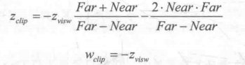
Among them, Far and Near are the distances between the far and near cutting planes, respectively. Then, we can get the z component of NDC by homogeneous division.
As we know before, the depth value in depth texture is calculated by NDC using the following formula:
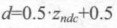
From the above formulas, we can derive the expression of Z(visw) expressed by d:
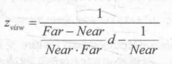
In the view space used by Unity, the z value corresponding to the camera is negative, so in order to get a positive representation of the depth value, we need to take the opposite of the above results. The final results are as follows:
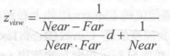
Its value range is the depth range of the cone, i.e. [Near,Far]. If we want to get the depth in the range between [0, 1], we just need to divide the result above by Far. Thus, 0 means that the point is in the same position as the camera, and 1 means that the point is in the far clipping plane of the cone. The results are as follows:
Fortunately, Unity provides two auxiliary functions for us to do the above calculation process - Linear EyeDepth and Linear 01Depth. Linear EyeDepth is responsible for converting the sampling result of depth texture to the depth value in view space, which is the Z(visw) we got above. Linear01Depth It returns a linear depth value in the range [0, 1], that is, Z(01), which we got above. The built-in _ZBufferParams variable is used inside these two functions to get the distance between the far and near clipping planes.
If we need to get the depth + normal texture, we can directly use the tex2D function to sample the _CameraDepth Normals Texture to get the depth and normal information stored in it. Unity provides an auxiliary function to decode our team's sampling results to get the depth and normal directions. This function is DecodeDepth Normal, which is defined in UnityCG.cginc:
inline void DecodeDepthNormal(float4 enc, out float depth,out float3 normal){
	depth = DecodeFloatRG(enc.zw);
	normal = DecodeViewNormalStereo(enc);
}Many times, we want to see the generated depth and normal texture for Shader debugging. Unity 5 provides a convenient way to view the depth and normal texture generated by the camera, using a frame debugger. The following figure shows the depth texture and depth + normal texture that the frame debugger sees.
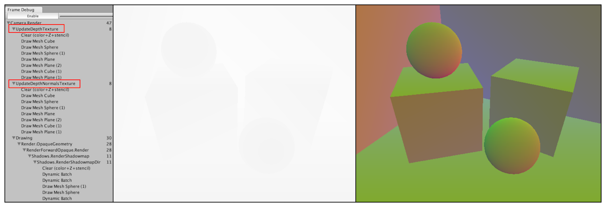
The depth texture seen by the frame debugger is the depth value of the non-linear space, and the depth + normal texture is the result of Unity coding. Sometimes, it is more useful to show the depth information in linear space or the normal direction after decoding. At this point, we can output the converted or decoded depth and normal values in the chip shader by ourselves, as shown in the following figure.
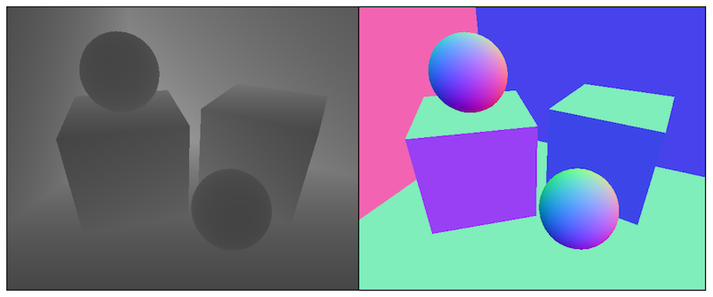
The output code is very simple. We can use code like the following to output the linear depth value:
Or output normal direction:float depth = SMAPLE_DEPTH_TEXTURE(_CameraDepthTexture,i.uv); float linearDepth = Linear01Depth(depth); return fixed4(linearDepth,linearDepth,linearDepth,1.0);
fixed3 normal = DecodeViewNormalStereo(tex2D(_CameraDepthNormalsTexture, i.uv).xy);
return fixed4(normal * 0.5 + 0.5, 1.0);
When looking at deep textures, we may get a picture that is almost black or white. At this point, we can reduce the distance of the camera's far clipping plane (Unity defaults to 1000), so that the cone's range covers the area where the scene is located. This is because projection transformation needs to cover all the depth areas from the near clipping plane to the far clipping plane. When the distance from the far clipping plane is too large, the distance from the camera will be mapped to a very small depth value. If the scene is a closed area, then the picture will look almost completely black. On the contrary, if the scene is an open area and the object is far away from the camera, the picture will be almost completely white.
Re-discussion on Motion Ambiguity
Previously, we learned how to simulate motion blurring by mixing multiple screen images. However, another more widely used technique is the use of velocity maps. Velocity maps store the speed of each pixel, which is then used to determine the direction and size of blurring. There are many ways to generate speed buffer. One way is to render the speed of all objects in the scene into a texture. However, the disadvantage of this method is that it needs to modify the Shader code of all objects in the scene, so that it can add computational speed code and output it to a rendering texture.
In Chapter 27, GPU Gems introduces a method of generating velocity map. This method calculates the position of each pixel in the world space by using the depth texture in the element shader, which is obtained by transforming the vertex coordinates under NDC by using the inverse matrix of the current perspective * projection matrix. After obtaining the vertex coordinates in the world space, we calculate the position difference between the previous frame and the current frame to generate the speed of the pixel. The advantage of this method is that it can simulate the whole effect in a screen post-processing step, but the disadvantage is that it requires two matrix multiplication operations in the chip shader, which has an impact on the performance.
In order to use depth texture to simulate motion blurring, we make the following preparations:
1) New scenes, remove sky boxes
2) Build a scene to test motion blurring, construct a method including three walls, and place four cubes.
3) Create a new script MotionBlurWithDepthTexture on the camera.
4) Create a new Shader Chapter 13-Motion Blur WithDepth Texture
Let's write the MotionBlurWithDepthTexture.cs script first
public class MotionBlurWithDepthTexture : PostEffectsBase {

	public Shader motionBlurShader;
	private Material motionBlurMaterial = null;

	public Material material {
		get {
			motionBlurMaterial = CheckShaderAndCreateMaterial(motionBlurShader, motionBlurMaterial);
			return motionBlurMaterial;
		}
	}

	private Camera myCamera;
	public Camera camera {
		get {
			if (myCamera == null) {
				myCamera = GetComponent<Camera>();
			}
			return myCamera;
		}
	}
	//Define the size of blurred images used in motion blurring
	[Range(0.0f, 1.0f)]
	public float blurSize = 0.5f;

	//Save the view * projection matrix of the previous camera
	private Matrix4x4 previousViewProjectionMatrix;

	void OnEnable() {
		camera.depthTextureMode |= DepthTextureMode.Depth;

		previousViewProjectionMatrix = camera.projectionMatrix * camera.worldToCameraMatrix;
	}

	void OnRenderImage (RenderTexture src, RenderTexture dest) {
		if (material != null) {
			material.SetFloat("_BlurSize", blurSize);

			material.SetMatrix("_PreviousViewProjectionMatrix", previousViewProjectionMatrix);
			Matrix4x4 currentViewProjectionMatrix = camera.projectionMatrix * camera.worldToCameraMatrix;
			Matrix4x4 currentViewProjectionInverseMatrix = currentViewProjectionMatrix.inverse;
			material.SetMatrix("_CurrentViewProjectionInverseMatrix", currentViewProjectionInverseMatrix);
			previousViewProjectionMatrix = currentViewProjectionMatrix;

			Graphics.Blit (src, dest, material);
		} else {
			Graphics.Blit(src, dest);
		}
	}
}Shader "Unity Shaders Book/Chapter 13/Motion Blur With Depth Texture" {
Properties {
_MainTex ("Base (RGB)", 2D) = "white" {}
//Parameters used in blurring images
_BlurSize ("Blur Size", Float) = 1.0
}
SubShader {
CGINCLUDE
#include "UnityCG.cginc"
sampler2D _MainTex;
half4 _MainTex_TexelSize;
sampler2D _CameraDepthTexture;
float4x4 _CurrentViewProjectionInverseMatrix;
float4x4 _PreviousViewProjectionMatrix;
half _BlurSize;
struct v2f {
float4 pos : SV_POSITION;
half2 uv : TEXCOORD0;
half2 uv_depth : TEXCOORD1;
};
v2f vert(appdata_img v) {
v2f o;
o.pos = mul(UNITY_MATRIX_MVP, v.vertex);
o.uv = v.texcoord;
o.uv_depth = v.texcoord;
//Platform differentiation
#if UNITY_UV_STARTS_AT_TOP
if (_MainTex_TexelSize.y < 0)
o.uv_depth.y = 1 - o.uv_depth.y;
#endif
return o;
}
fixed4 frag(v2f i) : SV_Target {
// Get the depth buffer value at this pixel.
float d = SAMPLE_DEPTH_TEXTURE(_CameraDepthTexture, i.uv_depth);
// H is the viewport position at this pixel in the range -1 to 1.
float4 H = float4(i.uv.x * 2 - 1, i.uv.y * 2 - 1, d * 2 - 1, 1);
// Transform by the view-projection inverse.
float4 D = mul(_CurrentViewProjectionInverseMatrix, H);
// Divide by w to get the world position.
float4 worldPos = D / D.w;
// Current viewport position
float4 currentPos = H;
// Use the world position, and transform by the previous view-projection matrix.
float4 previousPos = mul(_PreviousViewProjectionMatrix, worldPos);
// Convert to nonhomogeneous points [-1,1] by dividing by w.
previousPos /= previousPos.w;
// Use this frame's position and last frame's to compute the pixel velocity.
float2 velocity = (currentPos.xy - previousPos.xy)/2.0f;
float2 uv = i.uv;
float4 c = tex2D(_MainTex, uv);
uv += velocity * _BlurSize;
for (int it = 1; it < 3; it++, uv += velocity * _BlurSize) {
float4 currentColor = tex2D(_MainTex, uv);
c += currentColor;
}
c /= 3;
return fixed4(c.rgb, 1.0);
}
ENDCG
Pass {
ZTest Always Cull Off ZWrite Off
CGPROGRAM
#pragma vertex vert
#pragma fragment frag
ENDCG
}
}
FallBack Off
}Global fog effect
Fog effect is a commonly used effect in games. Unity's built-in fog effect can produce a linear or exponential distance-based fog effect. However, in order to achieve these fog effects in the vertex/chip shader we write, we need to add # pragma multi_compile_fog instructions to Shader, and also need to use relevant built-in macros, such as UNITY_FOG_COORDS, UNITY_TRANSFER_FOG and UNITY_APPLY_FOG. The disadvantage of this method is that not only do we need to add relevant rendering stupidity to all objects in the scene, but also the effect that can be achieved is very limited. When we need to personalize fog effects, such as using height-based fog effects, it is no longer feasible to just use Unity's built-in fog effects.
We use a global fog effect implementation based on screen post-processing. In this way, we don't need to change the Shader code used by the rendered objects in the scene, but only rely on the steps of one screen post-processing. This method has a high degree of freedom. We can easily simulate various fog effects, such as uniform fog effect, linear/exponential distance-based fog effect, height-based fog effect, etc. We can get results similar to those in the following figure.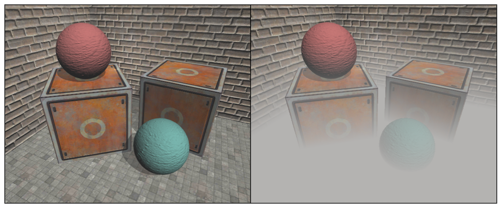
The key to the global fog effect based on screen post-processing is to reconstruct the position of each pixel in the world space according to the depth texture. Although we have achieved this requirement before when simulating motion blurring, that is, to construct the NDC coordinates of the current pixel, and then to get the coordinates of the world space pixels through the inverse matrix of the current camera's angle*projection matrix, such implementation requires matrix multiplication in the chip shader, which usually affects the performance of the game. We learn a fast way to reconstruct world coordinates from deep textures. Firstly, the method interpolates the cone ray (from the camera to a point in the image) in the image space, which stores the direction information of the pixel from the world space to the camera. Then, we multiply the ray with the depth value in the linearized view space and add the camera's world position to get the location of the pixel in the world space. When we get the world coordinates, we can easily use various formulas to simulate the global fog effect.
We know that a vertex coordinate in a coordinate system can be obtained by its offset from another vertex coordinate. The world coordinates of reconstructed pixels are also based on this idea. We only need to know the location of the camera in the world space and the offset of the pixel relative to the camera in the world space, and add them together to get the world coordinates of the pixel. The whole process can be represented by the following code:
float4 worldPos = _WorldSpaceCameraPos + linearDepth * interpolateRay;
Among them, _WorldSpace CameraPos is the location of the camera in the world space, which can be accessed directly by Unity's built-in variables. Linear Depth * interpolated Ray can calculate the offset of the pixel relative to the camera. Linear Depth is the linear depth value obtained by the depth texture. Interolated Ray is the ray output by the vertex shader and interpolated. It contains not only the direction of the pixel to the camera, but also the distance information.
Interpolated Ray is derived from the interpolation of a specific vector of four angles near the clipping plane. These four vectors contain the direction and distance information from them to the camera, which can be calculated by the camera's near-clipping plane distance, FOV and aspect ratio. The following figure shows some auxiliary vectors used in calculation.
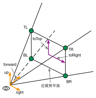
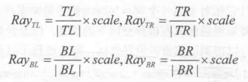
To facilitate calculation, we can first compute two vectors, toTop and toRight, which start at the center of the near clipping plane and point directly above and to the right of the camera, respectively. Their formulas are as follows:
Near is the distance near the clipping plane, FOV is the angle of view in the vertical direction. camera.up and camera.right correspond to the top and right of the camera respectively. When these two auxiliary vectors are obtained, we can calculate the direction of four angles relative to the camera. Let's take the upper left corner as an example. Its calculation formula is as follows:

Similarly, the calculation of the other three angles is similar:
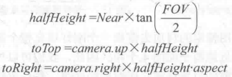
Note that the four vectors obtained above not only contain direction information, but also their modes correspond to the spatial distance from four points to the camera. Since the linear depth values we get are not the Euclidean distance from the point to the camera, but the distance in the z direction, we can not directly use the product of the depth values and the unit direction of the four angles to calculate their offset to the camera, as shown in the following figure.
In order to convert the depth value into the Euclidean distance of the camera, we take TL point as an example. According to the similar triangle principle, the ratio of the depth value of the pixel to the actual distance of the camera is equal to the ratio of the distance from the near clipping plane to the modulus of the TL vector on the ray where TL is located, that is, the ratio of the depth value of the pixel to the actual distance of the camera.
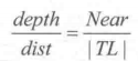
As a result, we need the Euclidean Distance dist of TL Distance Camera:
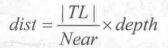
Because the four points are symmetrical, the modulus and TL of the other three vectors are equal. That is, we can multiply the same factor and unit vector to get their corresponding vector values:
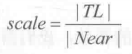
The principle of screen post-processing is to use specific material to render a quadrilateral surface that just fills the whole screen. The four vertices of the quadrilateral face correspond to the four corners of the nearly trimmed plane. Thus, we can transfer the above calculation results to the vertex shader. The vertex shader chooses its corresponding vector according to the current position, and then outputs it. After interpolation, the vertex shader passes it to the element shader to get interpolated Ray. We can use the formulas mentioned earlier to reconstruct the position of the pixel in the world space.
In the simple fog effect realization, we need to calculate a fog effect coefficient f as the mixing coefficient of mixing the original color and the fog color.There are many methods for calculating the fog efficiency factor F. In Unity's built-in fog effect implementation, three fog calculation methods are supported: linear, exponential and exponential square. When the distance z is given, the formulas for calculating f are as follows:float3 afterFog = f*fogColor + (1 - f) * origColor;
Linear:

Exponential:

Exponential Squared:

We use a method similar to linear fog to calculate the fog efficiency based on height. Specifically, given the height y of a point in the world space, the formula for calculating f is as follows:

In order to achieve fog effect based on screen post-processing in Unity, we need to do the following preparations.
1) Create a new scene and remove the sky box.
2) Build a room with three walls, two cubes and two spheres
3) Create a new script FogWithDepthTexture.cs on the camera.
4) Create a new Shader Chapter13-FogWithDepthTexture.
First, we write FogWithDepthTexture.cs.
public class FogWithDepthTexture : PostEffectsBase {

	public Shader fogShader;
	private Material fogMaterial = null;

	public Material material {
		get {
			fogMaterial = CheckShaderAndCreateMaterial(fogShader, fogMaterial);
			return fogMaterial;
		}
	}

	private Camera myCamera;
	public Camera camera {
		get {
			if (myCamera == null) {
				myCamera = GetComponent<Camera>();
			}
			return myCamera;
		}
	}

	private Transform myCameraTransform;
	public Transform cameraTransform {
		get {
			if (myCameraTransform == null) {
				myCameraTransform = camera.transform;
			}

			return myCameraTransform;
		}
	}

	//Controlling Fog Concentration
	[Range(0.0f, 3.0f)]
	public float fogDensity = 1.0f;

	//Control fog color
	public Color fogColor = Color.white;
	//Initial height of fog effect
	public float fogStart = 0.0f;
	//The termination height of fog effect.
	public float fogEnd = 2.0f;

	void OnEnable() {
		camera.depthTextureMode |= DepthTextureMode.Depth;
	}

	void OnRenderImage (RenderTexture src, RenderTexture dest) {
		if (material != null) {
			Matrix4x4 frustumCorners = Matrix4x4.identity;
			//Firstly, the vectors corresponding to the four corners of the near clipping plane are calculated.
			float fov = camera.fieldOfView;
			float near = camera.nearClipPlane;
			float aspect = camera.aspect;

			float halfHeight = near * Mathf.Tan(fov * 0.5f * Mathf.Deg2Rad);
			Vector3 toRight = cameraTransform.right * halfHeight * aspect;
			Vector3 toTop = cameraTransform.up * halfHeight;

			Vector3 topLeft = cameraTransform.forward * near + toTop - toRight;
			float scale = topLeft.magnitude / near;

			topLeft.Normalize();
			topLeft *= scale;

			Vector3 topRight = cameraTransform.forward * near + toRight + toTop;
			topRight.Normalize();
			topRight *= scale;

			Vector3 bottomLeft = cameraTransform.forward * near - toTop - toRight;
			bottomLeft.Normalize();
			bottomLeft *= scale;

			Vector3 bottomRight = cameraTransform.forward * near + toRight - toTop;
			bottomRight.Normalize();
			bottomRight *= scale;
			//Store four vectors in frustum Corners of matrix type
			frustumCorners.SetRow(0, bottomLeft);
			frustumCorners.SetRow(1, bottomRight);
			frustumCorners.SetRow(2, topRight);
			frustumCorners.SetRow(3, topLeft);

			material.SetMatrix("_FrustumCornersRay", frustumCorners);

			material.SetFloat("_FogDensity", fogDensity);
			material.SetColor("_FogColor", fogColor);
			material.SetFloat("_FogStart", fogStart);
			material.SetFloat("_FogEnd", fogEnd);

			Graphics.Blit (src, dest, material);
		} else {
			Graphics.Blit(src, dest);
		}
	}
}Shader "Unity Shaders Book/Chapter 13/Fog With Depth Texture" {
Properties {
_MainTex ("Base (RGB)", 2D) = "white" {}
_FogDensity ("Fog Density", Float) = 1.0
_FogColor ("Fog Color", Color) = (1, 1, 1, 1)
_FogStart ("Fog Start", Float) = 0.0
_FogEnd ("Fog End", Float) = 1.0
}
SubShader {
CGINCLUDE
#include "UnityCG.cginc"
float4x4 _FrustumCornersRay;
sampler2D _MainTex;
half4 _MainTex_TexelSize;
sampler2D _CameraDepthTexture;
half _FogDensity;
fixed4 _FogColor;
float _FogStart;
float _FogEnd;
struct v2f {
float4 pos : SV_POSITION;
half2 uv : TEXCOORD0;
half2 uv_depth : TEXCOORD1;
float4 interpolatedRay : TEXCOORD2;
};
v2f vert(appdata_img v) {
v2f o;
o.pos = mul(UNITY_MATRIX_MVP, v.vertex);
o.uv = v.texcoord;
o.uv_depth = v.texcoord;
#if UNITY_UV_STARTS_AT_TOP
if (_MainTex_TexelSize.y < 0)
o.uv_depth.y = 1 - o.uv_depth.y;
#endif
int index = 0;
if (v.texcoord.x < 0.5 && v.texcoord.y < 0.5) {
index = 0;
} else if (v.texcoord.x > 0.5 && v.texcoord.y < 0.5) {
index = 1;
} else if (v.texcoord.x > 0.5 && v.texcoord.y > 0.5) {
index = 2;
} else {
index = 3;
}
#if UNITY_UV_STARTS_AT_TOP
if (_MainTex_TexelSize.y < 0)
index = 3 - index;
#endif
o.interpolatedRay = _FrustumCornersRay[index];
return o;
}
fixed4 frag(v2f i) : SV_Target {
float linearDepth = LinearEyeDepth(SAMPLE_DEPTH_TEXTURE(_CameraDepthTexture, i.uv_depth));
float3 worldPos = _WorldSpaceCameraPos + linearDepth * i.interpolatedRay.xyz;
float fogDensity = (_FogEnd - worldPos.y) / (_FogEnd - _FogStart);
fogDensity = saturate(fogDensity * _FogDensity);
fixed4 finalColor = tex2D(_MainTex, i.uv);
finalColor.rgb = lerp(finalColor.rgb, _FogColor.rgb, fogDensity);
return finalColor;
}
ENDCG
Pass {
ZTest Always Cull Off ZWrite Off
CGPROGRAM
#pragma vertex vert
#pragma fragment frag
ENDCG
}
}
FallBack Off
}On Edge Detection
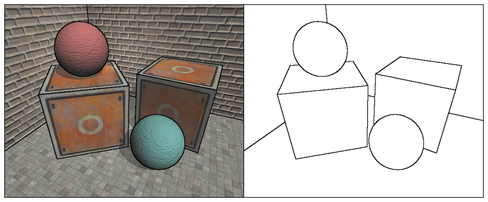
Previously, we introduced how to use Sobel operator to detect the edge of screen image and achieve the effect of edge tracing. However, this method of edge detection directly using color information will produce many edge lines that we do not want to get, as shown in the following figure.
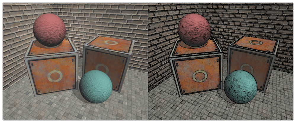
It can be seen that the texture, shadow and other positions of the object are also depicted on the black edge, which is often not what we want to see. We will learn how to detect edges in depth and normal texture. These images are not affected by texture and illumination, but only preserve the model information of the object rendered for a single money. In this way, the edges detected are more reliable. We can get results similar to those in the following figure.
We use Robert operator for edge detection. The convolution kernels it uses are shown in the following figure.
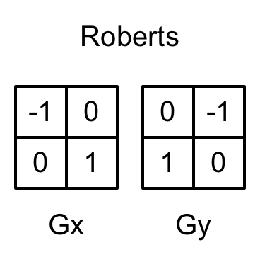
The essence of Roberts operator is to calculate the interpolation of the upper left corner and the lower right corner, multiply the difference between the upper right corner and the lower left corner, as the basis for evaluating the edge. In the following implementations, we will also take the diagonal depth or normal value and compare the difference between them. If we exceed a certain threshold, we think that there is an edge between them.
We will make the following preparations.
1) Create a new scene and remove the sky box.
2) Build a room with three walls, two cubes and two spheres.
3) Add EdgeDetectNormals AndDepth. CS script to the camera
4) Create a new Shader Chapter 13-Edge Detect Normal AndDepth.
Let's first modify the EdgeDetectNormals AndDepth. CS script
public class EdgeDetectNormalsAndDepth : PostEffectsBase {

	public Shader edgeDetectShader;
	private Material edgeDetectMaterial = null;
	public Material material {
		get {
			edgeDetectMaterial = CheckShaderAndCreateMaterial(edgeDetectShader, edgeDetectMaterial);
			return edgeDetectMaterial;
		}
	}

	[Range(0.0f, 1.0f)]
	public float edgesOnly = 0.0f;

	public Color edgeColor = Color.black;

	public Color backgroundColor = Color.white;

	public float sampleDistance = 1.0f;

	public float sensitivityDepth = 1.0f;

	public float sensitivityNormals = 1.0f;

	void OnEnable() {
		GetComponent<Camera>().depthTextureMode |= DepthTextureMode.DepthNormals;
	}

	//[Image Effect Opaque] Keep transparent objects from being edged
	[ImageEffectOpaque]
	void OnRenderImage (RenderTexture src, RenderTexture dest) {
		if (material != null) {
			material.SetFloat("_EdgeOnly", edgesOnly);
			material.SetColor("_EdgeColor", edgeColor);
			material.SetColor("_BackgroundColor", backgroundColor);
			material.SetFloat("_SampleDistance", sampleDistance);
			material.SetVector("_Sensitivity", new Vector4(sensitivityNormals, sensitivityDepth, 0.0f, 0.0f));

			Graphics.Blit(src, dest, material);
		} else {
			Graphics.Blit(src, dest);
		}
	}
}Shader "Unity Shaders Book/Chapter 13/Edge Detection Normals And Depth" {
Properties {
_MainTex ("Base (RGB)", 2D) = "white" {}
_EdgeOnly ("Edge Only", Float) = 1.0
_EdgeColor ("Edge Color", Color) = (0, 0, 0, 1)
_BackgroundColor ("Background Color", Color) = (1, 1, 1, 1)
_SampleDistance ("Sample Distance", Float) = 1.0
_Sensitivity ("Sensitivity", Vector) = (1, 1, 1, 1)
}
SubShader {
CGINCLUDE
#include "UnityCG.cginc"
sampler2D _MainTex;
half4 _MainTex_TexelSize;
fixed _EdgeOnly;
fixed4 _EdgeColor;
fixed4 _BackgroundColor;
float _SampleDistance;
half4 _Sensitivity;
sampler2D _CameraDepthNormalsTexture;
struct v2f {
float4 pos : SV_POSITION;
half2 uv[5]: TEXCOORD0;
};
v2f vert(appdata_img v) {
v2f o;
o.pos = mul(UNITY_MATRIX_MVP, v.vertex);
half2 uv = v.texcoord;
o.uv[0] = uv;
#if UNITY_UV_STARTS_AT_TOP
if (_MainTex_TexelSize.y < 0)
uv.y = 1 - uv.y;
#endif
o.uv[1] = uv + _MainTex_TexelSize.xy * half2(1,1) * _SampleDistance;
o.uv[2] = uv + _MainTex_TexelSize.xy * half2(-1,-1) * _SampleDistance;
o.uv[3] = uv + _MainTex_TexelSize.xy * half2(-1,1) * _SampleDistance;
o.uv[4] = uv + _MainTex_TexelSize.xy * half2(1,-1) * _SampleDistance;
return o;
}
half CheckSame(half4 center, half4 sample) {
half2 centerNormal = center.xy;
float centerDepth = DecodeFloatRG(center.zw);
half2 sampleNormal = sample.xy;
float sampleDepth = DecodeFloatRG(sample.zw);
// difference in normals
// do not bother decoding normals - there's no need here
half2 diffNormal = abs(centerNormal - sampleNormal) * _Sensitivity.x;
int isSameNormal = (diffNormal.x + diffNormal.y) < 0.1;
// difference in depth
float diffDepth = abs(centerDepth - sampleDepth) * _Sensitivity.y;
// scale the required threshold by the distance
int isSameDepth = diffDepth < 0.1 * centerDepth;
// return:
// 1 - if normals and depth are similar enough
// 0 - otherwise
return isSameNormal * isSameDepth ? 1.0 : 0.0;
}
fixed4 fragRobertsCrossDepthAndNormal(v2f i) : SV_Target {
half4 sample1 = tex2D(_CameraDepthNormalsTexture, i.uv[1]);
half4 sample2 = tex2D(_CameraDepthNormalsTexture, i.uv[2]);
half4 sample3 = tex2D(_CameraDepthNormalsTexture, i.uv[3]);
half4 sample4 = tex2D(_CameraDepthNormalsTexture, i.uv[4]);
half edge = 1.0;
edge *= CheckSame(sample1, sample2);
edge *= CheckSame(sample3, sample4);
fixed4 withEdgeColor = lerp(_EdgeColor, tex2D(_MainTex, i.uv[0]), edge);
fixed4 onlyEdgeColor = lerp(_EdgeColor, _BackgroundColor, edge);
return lerp(withEdgeColor, onlyEdgeColor, _EdgeOnly);
}
ENDCG
Pass {
ZTest Always Cull Off ZWrite Off
CGPROGRAM
#pragma vertex vert
#pragma fragment fragRobertsCrossDepthAndNormal
ENDCG
}
}
FallBack Off
}