Simple Experiments of Firewall Dual Hot Standby
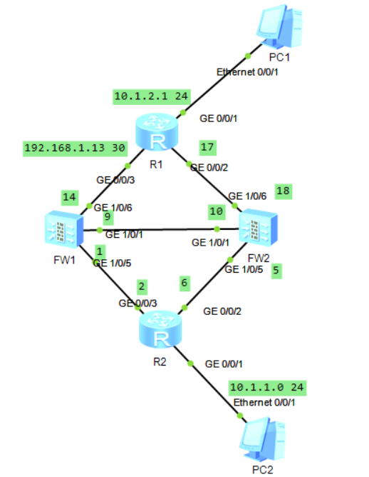
Experimental topo:
The purpose of the experiment is:
- Familiar with dual hot standby principle
- Network Planning of Dual Machine Hot Standby
Experiments need:
- Enterprises deploy dual hot standby and connect routers upstream and downstream in the main standby mode.
- IP address configuration as shown above
- Interworking of the whole network
Configuration ideas:
1. Each interface of two firewalls configures the corresponding address, and joins the area (interface use should be consistent). If after configuring HRP, it is found that both are master or both are ready, it is often the reason why the interface does not add the area.
FW1:
interface GigabitEthernet1/0/1
 ip address 192.168.1.9 255.255.255.252
interface GigabitEthernet1/0/5
 ip address 192.168.1.1 255.255.255.252
interface GigabitEthernet1/0/6
 ip address 192.168.1.14 255.255.255.252
2. Configure ospf, pay attention not to announce the heartbeat when announcing, the heartbeat does not go business, the upstream and downlink switch with VRRP, the router with ospf:
FW1:
ospf 1
 area 0.0.0.0
  network 192.168.1.0 0.0.0.3
  network 192.168.1.12 0.0.0.3
FW2:
ospf 1
 area 0.0.0.0
  network 192.168.1.4 0.0.0.3
  network 192.168.1.16 0.0.0.3
R1:
ospf 1
 area 0.0.0.0
  network 0.0.0.0 255.255.255.255  ---This command declares all interfacesIPaddress
R2:
ospf 1
 area 0.0.0.0
  network 0.0.0.0 255.255.255.255  ---This command declares all interfacesIPaddress
3. Configure HRP to turn on dual hot standby:
FW1:
hrp enable
 hrp interface GigabitEthernet1/0/1 remote 192.168.1.10
 hrp track interface GigabitEthernet1/0/5
 hrp track interface GigabitEthernet1/0/6
FW2:
hrp enable
 hrp standby-device
 hrp interface GigabitEthernet1/0/1 remote 192.168.1.9
 hrp track interface GigabitEthernet1/0/5
 hrp track interface GigabitEthernet1/0/6
4. Following the above steps, FW1 and FW2 will compare the main wall and the backup wall, and there will be corresponding changes:
HRP_M[fw1] ---Main wall
HRP_S[fw2] ---Backup wall
5. Writing security policy on FW1, FW2 will automatically synchronize the configuration of FW1:
security-policy
 default action permit
 rule name a1
  source-zone trust
  destination-zone untrust
  action permit
The experimental results are as follows:
PC1 accesses PC2:
PC>ping 10.1.2.2
Ping 10.1.2.2: 32 data bytes, Press Ctrl_C to break
From 10.1.2.2: bytes=32 seq=1 ttl=254 time=62 ms
From 10.1.2.2: bytes=32 seq=2 ttl=254 time=63 ms
From 10.1.2.2: bytes=32 seq=3 ttl=254 time=62 ms
From 10.1.2.2: bytes=32 seq=4 ttl=254 time=63 ms
From 10.1.2.2: bytes=32 seq=5 ttl=254 time=62 ms