1. Background
Calibration is an everlasting pain for robot developers.Although the method was used decades ago, everyone who wants to use the camera has to go through a painful pit, without easily getting the good bag.
In the application of robot vision, hand-eye calibration is a very basic and critical problem.Simply speaking, the purpose of hand-eye calibration is to get the relationship between the coordinate system of the robot and the coordinate system of the camera, and finally transfer the results of visual recognition to the coordinate system of the robot.
There are two forms of hand-eye calibration in the industry. Depending on where the camera is fixed, if the camera and the end of the robot are fixed together, it is called eye in hand. If the camera is fixed on the base outside the robot, it is called eye to hand.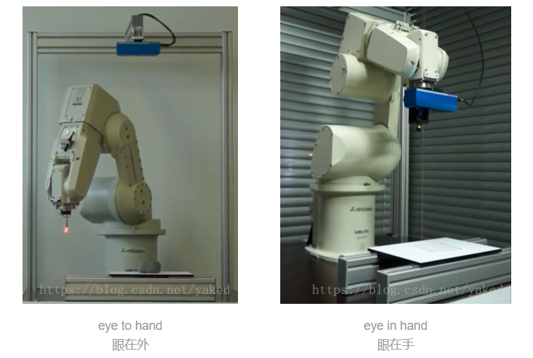
2. Mathematical description of hand-eye relationship
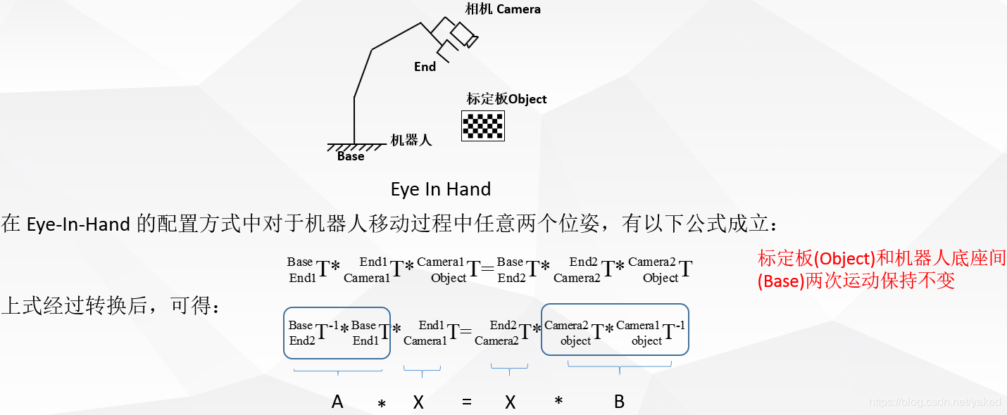
- eye in hand, under this relationship, the relationship between the robot base and the calibration board remains unchanged after two movements.The amount of solution is the position-posture relationship between the camera and the end coordinate system of the robot.
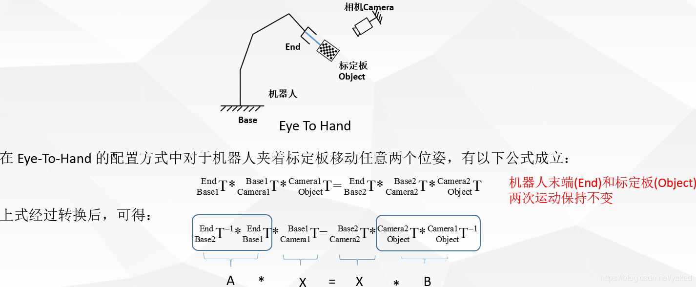
- eye to hand, under this relationship, the position-posture relationship between the end of the robot and the calibration board remains unchanged after two movements.The amount of solution is the position-posture relationship between the camera and the robot base coordinate system.
3. Solution of AX = XB problem
- Shiu Y C, Ahmad S. Calibration of wrist-mounted robotic sensors by
solving homogeneous transform equations of the form AX=XB[J]. IEEE
Transactions on Robotics & Automation, 1989, 5(1):16-29.
Related online English tutorials http://math.loyola.edu/~mili/Calibration/index.html There are also matlab codes for AX= XB that can be used.
There are also some package s available under ROS
https://github.com/IFL-CAMP/easy_handeye
http://visp-doc.inria.fr/doxygen/visp-daily/calibrateTsai_8cpp-example.html#_a0
http://campar.in.tum.de/Chair/HandEyeCalibration TUM also has many reference links for hand-eye calibration solutions here
4. Other References
https://mp.weixin.qq.com/s/nJx1dlpBXaL2_iT_J4W5Kg Qiu Qiang Flyqq WeChat Article
https://blog.csdn.net/u011089570/article/details/47945733 Good picture
https://blog.csdn.net/qq_16481211/article/details/79764730 Partial halocon code
https://blog.csdn.net/qq_16481211/article/details/79767100 halocon code
https://blog.csdn.net/happyjume/article/details/80847822 Part of the Principle
https://blog.csdn.net/zhang970187013/article/details/81098175 UR5 and easy hand eye
In general, two-step method is used to solve the basic equation, that is, the rotation part is solved from the basic equation, and then the translation part is solved.
https://blog.csdn.net/yunlinwang/article/details/51622143
5. Hand-eye calibration solution under Matlab
My Matlab version R2013a, which uses some angle conversion functions and displays of the Robot Toolbox, is installed and basic using reference here: https://blog.csdn.net/yaked/article/details/48933603
Camera and Robot are eye-to-hand modes. Robot is a 6-axis Canadian Kinova arm. Robot pose is x,y,z,rx,ry,rz with end relative to base, in meters and radians
2017.08.29Kinova_pose_all_10_1.txt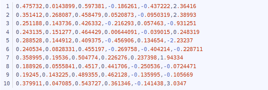
pattern pose is the calibration plate x, y, z, rx, ry, rz, in meters and radians relative to the camera
2017.08.29Pattern_pose_all_10_1.txt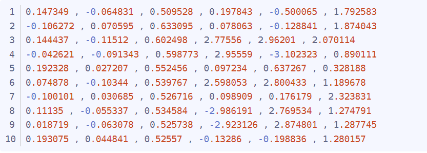
This Matlab file invokes data for offline solution. http://math.loyola.edu/~mili/Calibration/index.html This part of Registering Two Sets of 6DoF Data with 1 Unknown, has a code download, download named shiu.m and tsai.m for call by the following program
Jaco_handeye_rewrite_10.m
%%  Eye to Hand calibration with Ensenso N20 and Kinova robotics arm.
% input : Pattern pose to camera and arm cartesian pose in base coordiante.
% output: The left eye of Ensenso N20 to the arm base coordiante.
%
% Robot Pose(Homogeneous) stored in cell A. -------------------10 pose
%
clear;
close all;
clc;

 JacoCartesianPose = importdata('D:\\jaco\\2017.08.29Kinova_pose_all_10_1.txt');


[m,n] = size(JacoCartesianPose); % 10* 6
A = cell(1,m); % 1*10

for i = 1: 1: m
   A{1,i} = transl(JacoCartesianPose(i,1), JacoCartesianPose(i,2), JacoCartesianPose(i,3)) * trotx(JacoCartesianPose(i,4)) * troty(JacoCartesianPose(i,5))* trotz(JacoCartesianPose(i,6));
end

% Pattern Pose(Homogeneous) stored in  cell B.
patternInCamPose = importdata('D:\\jaco\\2017.08.29Pattern_pose_all_10_1.txt');

[melem,nelem] = size(patternInCamPose); % 10*6
B=cell(1,melem);
for x=1:1:melem
   B{1,x} = transl(patternInCamPose(x,1), patternInCamPose(x,2), patternInCamPose(x,3)) * trotx(patternInCamPose(x,4)) * troty(patternInCamPose(x,5))* trotz(patternInCamPose(x,6));
end
%
%Robot Posture Acquisition Remember to get as a pentagon, reference Tsai Papers
n2=m;
TA=cell(1,n2);
TB=cell(1,n2);


%--------------------- 10 -----------------------------------
 for j=[1,6]% Only begin.

     TA{1,j}=A{1,j+1}*inv(A{1,j});
     TA{1,j+1}=A{1,j+2}*inv(A{1,j+1});
     TA{1,j+2}=A{1,j+3}*inv(A{1,j+2});
     TA{1,j+3}=A{1,j+4}*inv(A{1,j+3});
     TA{1,j+4}=A{1,j}*inv(A{1,j+4});

     TB{1,j}=B{1,j+1}*inv(B{1,j});
     TB{1,j+1}=B{1,j+2}*inv(B{1,j+1});
     TB{1,j+2}=B{1,j+3}*inv(B{1,j+2});
     TB{1,j+3}=B{1,j+4}*inv(B{1,j+3});
     TB{1,j+4}=B{1,j}*inv(B{1,j+4});

 end

 %M1=[TA{1,1} TA{1,2} TA{1,3} TA{1,4} TA{1,5} TA{1,6} TA{1,7} TA{1,8} TA{1,9}...
     TA{1,10}  ];
 %M2=[TB{1,1} TB{1,2} TB{1,3} TB{1,4} TB{1,5} TB{1,6} TB{1,7} TB{1,8} TB{1,9}...
     TB{1,10}   ];

 M1=[TA{1,1} TA{1,2} TA{1,3} TA{1,4} TA{1,5} TA{1,6} TA{1,7} TA{1,8} TA{1,9} ];
 M2=[TB{1,1} TB{1,2} TB{1,3} TB{1,4} TB{1,5} TB{1,6} TB{1,7} TB{1,8} TB{1,9} ];
%--------------------- 10 -----------------------------------

C_Tsai=tsai(M1,M2);
T_Tsai =  (transl(C_Tsai))';
C_Tsai_rad = tr2rpy(C_Tsai);
C_Tsai_rpy_rx_ry_rz =rad2deg(C_Tsai_rad);
fprintf('Tsai(rad) = \n%f, %f, %f, %f, %f, %f\n',T_Tsai(1,1), T_Tsai(1,2), T_Tsai(1,3), C_Tsai_rad(1,1), C_Tsai_rad(1,2), C_Tsai_rad(1,3));
fprintf('Tsai(deg) = \n%f, %f, %f, %f, %f, %f\n\n',T_Tsai(1,1), T_Tsai(1,2), T_Tsai(1,3), C_Tsai_rpy_rx_ry_rz(1,1), C_Tsai_rpy_rx_ry_rz(1,2), C_Tsai_rpy_rx_ry_rz(1,3));
C_Shiu=shiu(M1,M2);
T_Shiu= [C_Shiu(1,4) C_Shiu(2,4) C_Shiu(3,4)] ;
C_Shiu_rad = tr2rpy(C_Shiu);
C_Shiu_rpy_rx_ry_rz = rad2deg(C_Shiu_rad);
fprintf('Shiu(rad) = \n%f, %f, %f, %f, %f, %f\n',T_Shiu(1,1), T_Shiu(1,2), T_Shiu(1,3), C_Shiu_rad(1,1), C_Shiu_rad(1,2), C_Shiu_rad(1,3));
fprintf('Shiu(deg) = \n%f, %f, %f, %f, %f, %f\n\n',T_Shiu(1,1), T_Shiu(1,2), T_Shiu(1,3), C_Shiu_rpy_rx_ry_rz(1,1), C_Shiu_rpy_rx_ry_rz(1,2), C_Shiu_rpy_rx_ry_rz(1,3));
C_Ijrr=ijrr1995(M1,M2);
T_ijrr= [C_Ijrr(1,4) C_Ijrr(2,4) C_Ijrr(3,4)] ;
C_ijrr_rad = tr2rpy(C_Ijrr);
C_ijrr_rpy_rx_ry_rz = rad2deg(C_ijrr_rad);
fprintf('Ijrr(rad) = \n%f, %f, %f, %f, %f, %f\n',C_Ijrr(1,1), C_Ijrr(1,2), C_Ijrr(1,3), C_ijrr_rad(1,1), C_ijrr_rad(1,2), C_ijrr_rad(1,3));
fprintf('Ijrr(deg) = \n%f, %f, %f, %f, %f, %f\n\n',C_Ijrr(1,1), C_Ijrr(1,2), C_Ijrr(1,3), C_ijrr_rpy_rx_ry_rz(1,1), C_ijrr_rpy_rx_ry_rz(1,2), C_ijrr_rpy_rx_ry_rz(1,3));
%%%%%%%%%%%%%%%%%%%%%%%%%%%%%%%%%%%%%%%%%%%%%%
% robotHcam  =[ -0.076, -0.674, 0.760631455868699, 178.7221124879378, -0.0735038591212, -11.5304192925905 ];
% robotHcam1 = transl(robotHcam(1,1), robotHcam(1,2), robotHcam(1,3)) * trotx(robotHcam(1,4),'deg') * troty(robotHcam(1,5),  'deg')* trotz(robotHcam(1,6), 'deg')* trotx(90,'deg'); % rotx 90
robotHcam  =[ 0.013, -0.94, 0.86, -90.0, 0.0, 0.0 ];
% robotHcam  =[ 0.25, 0.22, 1.1, 180.0, 0.0, 90.0 ]; % bind to the stack
 robotHcam1 = transl(robotHcam(1,1), robotHcam(1,2), robotHcam(1,3)) * trotx(robotHcam(1,4),'deg') * troty(robotHcam(1,5),  'deg')* trotz(robotHcam(1,6), 'deg');
fprintf('robotHcam used in Program(rad) = \n%f, %f, %f, %f, %f, %f\n',robotHcam(1,1), robotHcam(1,2), robotHcam(1,3), deg2rad(robotHcam(1,4)), deg2rad(robotHcam(1,5)), deg2rad(robotHcam(1,6)));
fprintf('robotHcam used in Program(deg) = \n%f, %f, %f, %f, %f, %f\n\n',robotHcam(1,1), robotHcam(1,2), robotHcam(1,3), robotHcam(1,4), robotHcam(1,5), robotHcam(1,6));
 t1 = eye(4);
trplot(t1,'frame','R','arrow','width', '1', 'color', 'r', 'text_opts', {'FontSize', 10, 'FontWeight', 'light'},'view', [-0.3 0.5 0.6],'thick',0.9,'dispar',0.8 );%  Display Robot coordinate
hold on;
trplot(robotHcam1,'frame','C',  'color', 'black'); %  Display Camera coordinate used in Program
trplot(C_Tsai,'frame','T',  'color', 'b'); %  Display Tsai
trplot(C_Shiu,'frame','S',  'color', 'g'); %  Display Shiu
eye to hand constructs A and B.When using eye in hand, the matrix is reversed differently.That is, TA{1,j}=A{1,j+1}*inv(A{1,j}); and TB{1,j}=B{1,j+1}*inv(B{1,j}); the opposite is different, be careful.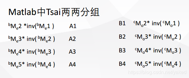
clc;
clear;
close all;

% D:\jaco\ConsoleApplication1/get_saveCartesian.cpp-Kinova_pose.txt
robotAeef = [-0.0860801, -0.641813, -0.0987199, 3.13316, 0.000389122, -0.297456];
robotBeef = transl(robotAeef(1,1), robotAeef(1,2), robotAeef(1,3)) * trotx(robotAeef(1,4)) * troty(robotAeef(1,5))* trotz(robotAeef(1,6));

% D:\jaco\C#\nxCsExamples.sln - Pattern_pose_all.txt
camAobj = [0.011651 , -0.069043 , 0.857845 , -3.12825 , 3.137609 , 3.048224];

camBobj =transl(camAobj(1,1), camAobj(1,2), camAobj(1,3)) * trotx(camAobj(1,4)) * troty(camAobj(1,5))* trotz(camAobj(1,6));
robotAcam = robotBeef * inv(camBobj);

robotAcam_Trans0 = (transl(robotAcam))';
 fprintf('robotAcam_T = \n%f, %f, %f\n',robotAcam_Trans0(1,1), robotAcam_Trans0(1,2), robotAcam_Trans0(1,3));
robotAcam_R_rad = tr2rpy((robotAcam));
fprintf('robotAcam_R(rad) = \n%f, %f, %f\n',robotAcam_R_rad(1,1), robotAcam_R_rad(1,2), robotAcam_R_rad(1,3));
R_degree0 = rad2deg(robotAcam_R_rad);
fprintf('robotAcam_R(deg) = \n%f, %f, %f\n\n',R_degree0(1,1), R_degree0(1,2), R_degree0(1,3));
% [theta, v] = tr2angvec(robotAcam)

% robotAcam = [
% robotAcam(1, 1) robotAcam(1, 2) robotAcam(1, 3) -0.097;
% robotAcam(2, 1) robotAcam(2, 2) robotAcam(2, 3) -0.695;
% robotAcam(3, 1) robotAcam(3,2) robotAcam(3, 3) robotAcam(3, 4);
% 0 0 0 1;
% ]
% Trans1 = (transl(robotAcam))'
% R_rad1 = tr2rpy((robotAcam))
% R_degree1 = rad2deg(R_rad1)

fprintf('===============Test point===============\n');
%  camAobj2= [   0.011634 , -0.068815 , 0.858039 , -3.124779 , 3.139759 , 3.046957]; % Workspace home.
 camAobj2= [  -0.102468 , -0.059197 , 0.858 , -3.127464 , 3.136249 , 3.053341
];

camBobj2 = transl(camAobj2(1,1), camAobj2(1,2), camAobj2(1,3)) * trotx(camAobj2(1,4)) * troty(camAobj2(1,5))* trotz(camAobj2(1,6));
robotAobj2 = robotAcam * camBobj2;
 robotAobj2_T = (transl(robotAobj2))';
 fprintf('robotAobj2_T = \n%f, %f, %f\n',robotAobj2_T(1,1), robotAobj2_T(1,2), robotAobj2_T(1,3));
robotAobj2_R_rad = tr2rpy((robotAobj2));
fprintf('robotAobj2_R(rad) = \n%f, %f, %f\n',robotAobj2_R_rad(1,1), robotAobj2_R_rad(1,2), robotAobj2_R_rad(1,3));
robotAobj2_R_degree = rad2deg(robotAobj2_R_rad);
fprintf('robotAobj2_R(deg) = \n%f, %f, %f\n',robotAobj2_R_degree(1,1), robotAobj2_R_degree(1,2), robotAobj2_R_degree(1,3));
Planar Nine Point Calibration
When a RGB camera or a robot is used to capture only a plane (i.e., a fixed posture, the six degrees of freedom position and posture of the robot are simplified to only consider translation, the posture is given and fixed artificially, and the robot can move to the top of the target point), the problem can be simplified to point pair A (x1, y1) of the target pixel set of the planar RGB image and the robot on the plane (X1, Y1).Relationships.This is done by the camera recognizing the pixel points given to A, and then using the instructor to view the coordinates of the robot in the base coordinate system, as B.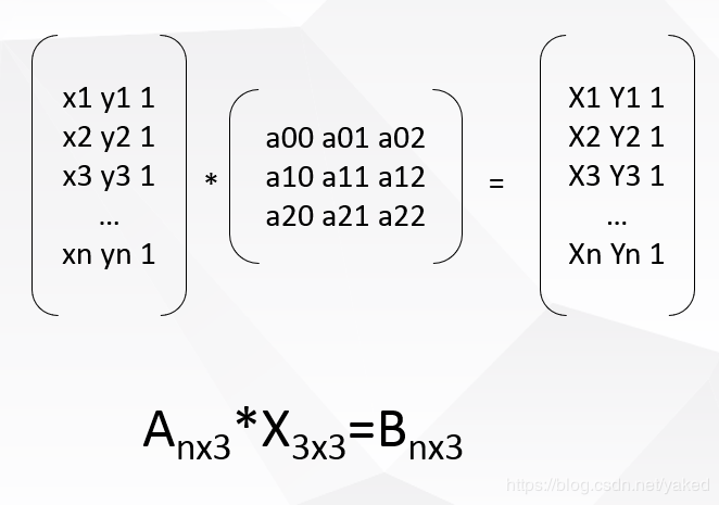
Camera coordinates and robot coordinates are written in homogeneous form. Projection matrix X is a 3x3 matrix. We need 6 sets of corresponding points to solve the minimum configuration solution.SVD is decomposed by singular values.
D:\opencv_work\cubeSolver\cv_solver\ConsoleApplication1\CV_SVD.cpp
D:\Matlab_work\handeye\NinePoints_Calibration.m
//Solve equation:AX=b

#include <cv.h>
#include<opencv2/opencv.hpp>
using namespace std;
using namespace cv;

int main(int argc, char** argv)
{
	printf("\nSolve equation:AX=b\n\n");

	//Mat A = (Mat_<float>(6, 3) <<
	//480.8, 639.4, 1,
	//227.1, 317.5, 1,
	//292.4, 781.6, 1,
	//597.4, 1044.1, 1,
	//557.7, 491.6, 1,
	//717.8, 263.7, 1
	//		 );// 4x3

	//Mat B = (Mat_<float>(6, 3) <<
	//197170, 185349, 1,
	//195830, 186789, 1,
	//196174, 184591, 1,
	//197787, 183176, 1,
	//197575, 186133, 1,
	//198466, 187335, 1
	//		 );

	Mat A = (Mat_<float>(4, 3) <<
	2926.36, 2607.79, 1,
	587.093, 2616.89, 1,
	537.031, 250.311, 1,
	1160.53, 1265.21, 1);// 4x3

	Mat B = (Mat_<float>(4, 3) <<
	320.389, 208.197, 1,
	247.77, 209.726, 1,
	242.809, 283.182, 1,
	263.152, 253.715, 1);


	Mat X;
	cout << "A=" << endl << A << endl;
	cout << "B=" << endl << B << endl;

	solve(A, B, X, CV_SVD);

	cout << "X=" << endl << X << endl;
	Mat a1 = (Mat_<float>(1, 3) << 1864, 1273, 1);
	Mat b1 = a1*X;
	cout << "b1=" << endl << b1 << endl;
	cout << "The true values are:" << "283.265, 253.049, 1" << endl;


	getchar();

	return 0;
}
https://docs.opencv.org/3.1.0/d2/de8/group__core__array.html#ga12b43690dbd31fed96f213eefead2373
Result comparison: left halcon C# (the third column is 0,0,1, not shown), right opencv c++, bottom is the result of Matlab, the three are consistent, algorithm detection passed.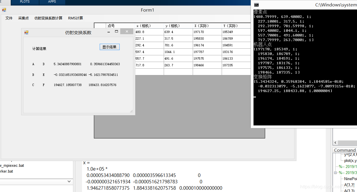
https://blog.csdn.net/Stones1025/article/details/100085338
This method uses point pairs to find the affine transformation matrix
#include "pch.h"
#include <iostream>

#include <cv.h>
#include<opencv2/opencv.hpp>

using namespace cv;


int main(int argc, char** argv)
{
	printf("\nSolve equation:AX=b\n\n");

	Point2f srcTri[3];
	srcTri[0] = Point2f(480.8f, 639.4f);
	srcTri[1] = Point2f(227.1f, 317.5f);
	srcTri[2] = Point2f(292.4f, 781.6f);

	Point2f dstTri[3];
	dstTri[0] = Point2f(197170.0f, 185349.0f);
	dstTri[1] = Point2f(195830.0f, 186789.0f);
	dstTri[2] = Point2f(196174.0f, 184591.0f);

	Mat warp_mat = getAffineTransform(srcTri, dstTri);
	// Compute image coordinates
	std::cout << "img_corners: \n" << srcTri << std::endl;
	std::cout << "robot_corners: \n" << dstTri << std::endl;
	std::cout << warp_mat << std::endl;

	//
	//[5.284835627018051, -0.00236967559639317, 194630.5662011061;
	//0.4056177440315953, -4.793119669651512, 188218.6997054448]

	return 0;
}