1) Experimental platform: punctual atom alpha Linux development board
2) Platform purchase address: https://item.taobao.com/item.htm?id=603672744434
2) Full set of experimental source code + manual + video download address: http://www.openedv.com/thread-300792-1-1.html
3) Students interested in punctual atomic Linux can add group discussion: 935446741
4) pay attention to the official account of the dot atom and get updated information.

Chapter 59 Linux LCD driver experiment
LCD Is a very common peripheral. In the bare metal chapter, we explained how to write it LCD Bare metal drive, in Linux lower LCD Is more widely used in collocation QT In this way GUI You can make very exquisite under the library UI Interface. In this chapter, we will learn how to Linux Lower drive LCD Screen.
Brief analysis of LCD driver under 59.1 Linux
59.1.1 Framebuffer device
Let's first review how LCD drivers are written in bare metal. The writing process of bare metal LCD drivers is as follows:
① Initialize the eLCDIF controller of I.MX6U, focusing on LCD screen width, height, hspw, hbp, hfp, vspw, vbp, vfp and other information.
② Initialize LCD pixel clock.
③ Set RGBLCD video memory.
④ The application program directly operates the LCD by operating the display memory to display characters, pictures and other information on the LCD.
In Linux, the application program finally displays characters, pictures and other information on the LCD by operating the display memory of RGB LCD. In the bare metal machine, we can freely allocate the video memory, but in the Linux system, the memory management is very strict. The video memory needs to be applied for, not what you want to use. Moreover, because of the existence of virtual memory, the video memory set by the driver and the video memory accessed by the application should be the same piece of physical memory.
In order to solve the above problems, framebuffer was born. Framebuffer is translated as frame buffer, abbreviated as FB. Therefore, if you see "framebuffer" or "FB" in future linux learning, your first reaction should think of RGBLCD or display device. FB is a mechanism that gathers all the hardware and software related to display in the system to create a virtual FB device. After we write the LCD driver, a device named / dev/fbX(X=0~n) will be generated. The application can access the LCD by accessing / dev/fbX. The LCD driver is enabled by default in the official Linux kernel of NXP, so we can see a device like / dev/fb0, as shown in figure 59.1.1.1:

Figure 59.1.1.1 /dev/fb0 device file
In figure 59.1.1.1, / dev/fb0 is the device file corresponding to the LCD, / dev/fb0 is a character device, so there must be a file_operations operation set, FB's file_ The operations operation set is defined in the drivers/video/fbdev/core/fbmem.c file as follows:
Example code 59.1.1.1 fb Set of operations for the device
1495 static const struct file_operations fb_fops = {
1496    .owner 	= THIS_MODULE,
1497    .read 		= fb_read,
1498    .write 	= fb_write,
1499    .unlocked_ioctl = fb_ioctl,
1500 #ifdef CONFIG_COMPAT
1501    .compat_ioctl = fb_compat_ioctl,
1502 #endif
1503    .mmap 		= fb_mmap,
1504    .open 		= fb_open,
1505    .release 	= fb_release,
1506 #ifdef HAVE_ARCH_FB_UNMAPPED_AREA
1507    .get_unmapped_area = get_fb_unmapped_area,
1508 #endif
1509 #ifdef CONFIG_FB_DEFERRED_IO
1510    .fsync 	= fb_deferred_io_fsync,
1511 #endif
1512    .llseek 	= default_llseek,
1513 };
about fb In this chapter, we focus on driving ALPHA On the development board LCD.
59.1.2 brief analysis of LCD driver
LCD bare metal routine is mainly divided into two parts:
① . obtain the screen parameters of LCD.
② Initialize the eLCDIF interface controller according to the screen parameter information.
For LCD screens with different resolutions, the driver code of the eLCDIF controller is the same. You only need to modify the corresponding screen parameters. Screen parameter information belongs to the content of screen device information, which must be put into the device tree. Therefore, the main work of our experiment in this chapter is to modify the device tree. The official device tree of NXP has added an LCD device node, but the LCD screen information of this node is written for the 4.3-inch 480 * 272 used by the official EVK development board of NXP, We need to change it to the screen parameters we use.
Let's take a brief look at the LCD driver under Linux officially written by NXP, open imx6ull.dtsi, and then find the lcdif node content, as shown below:
Example code 59.1.2.1 imx6ull.dtsi In the file lcdif Node content
1  lcdif: lcdif@021c8000 {
2              compatible = "fsl,imx6ul-lcdif", "fsl,imx28-lcdif";
3              reg = <0x021c8000 0x4000>;
4              interrupts = <GIC_SPI 5 IRQ_TYPE_LEVEL_HIGH>;
5              clocks = <&clks IMX6UL_CLK_LCDIF_PIX>,
6                   <&clks IMX6UL_CLK_LCDIF_APB>,
7                   <&clks IMX6UL_CLK_DUMMY>;
8              clock-names = "pix", "axi", "disp_axi";
9              status = "disabled";
10 };
Example code 59.1.2.1 Medium lcdif Node information is used by all users I.MX6ULL The boards of the chip are not complete lcdif Node information. Screen parameters need to be added according to different hardware platforms, such as imx6ull-alientek-emmc.dts Medium lcdif Add other attribute information to the node. From sample code 59.1.2.1 It can be seen that lcdif Nodal compatible The attribute value is“ fsl,imx6ul-lcdif"And“ fsl,imx28-lcdif",So in Linux Search these two strings in the source code to find them I.MX6ULL of LCD Driver file, this file is drivers/video/fbdev/mxsfb.c,mxsfb.c namely I.MX6ULL of LCD Driver file, in which the following contents can be found:
Example code 59.1.2.2 platform Lower LCD drive
1362 static const struct of_device_id mxsfb_dt_ids[] = {
1363    { .compatible = "fsl,imx23-lcdif", .data = &mxsfb_devtype[0], },
1364    { .compatible = "fsl,imx28-lcdif", .data = &mxsfb_devtype[1], },
1365    { /* sentinel */ }
1366 };
......
1625 static struct platform_driver mxsfb_driver = {
1626    .probe = mxsfb_probe,
1627    .remove = mxsfb_remove,
1628    .shutdown = mxsfb_shutdown,
1629    .id_table = mxsfb_devtype,
1630    .driver = {
1631           .name = DRIVER_NAME,
1632           .of_match_table = mxsfb_dt_ids,
1633           .pm = &mxsfb_pm_ops,
1634    },
1635 };
1636
1637 module_platform_driver(mxsfb_driver);
From sample code 59.1.2.2 It can be seen that this is a standard platform Drive, when the drive matches the device mxsfb_probe The function will execute. Look mxsfb_probe Function, let's take a brief look at it Linux lower Framebuffer Driven writing process, Linux The kernel will all Framebuffer Abstract as a fb_info The structure of, fb_info The structure contains Framebuffer The complete set of properties and operations of the device, so each Framebuffer Every device must have one fb_info. In other words, LCD The driver of is to build fb_info,And register with the system fb_info The process of. fb_info Structure defined in include/linux/fb.h In the document, the contents are as follows(Omit conditional compilation):
Example code 59.1.2.3 fb_info structural morphology
448 struct fb_info {
449     atomic_t count;
450     int node;
451     int flags;
452     struct mutex lock;          		/* mutex  			*/
453     struct mutex mm_lock;       		/* Mutex for fb_mmap and smem_ * domains*/
454     struct fb_var_screeninfo var;	/* Current variable parameter 		*/
455     struct fb_fix_screeninfo fix; 	/* Current fixed parameter 		*/
456     struct fb_monspecs monspecs;  	/* Current display characteristics 	*/
457     struct work_struct queue;       	/* Frame buffer event queue 	*/
458     struct fb_pixmap pixmap;        	/* Image hardware mapping		*/
459     struct fb_pixmap sprite;        	/* Cursor hardware mapping 		*/
460     struct fb_cmap cmap;            	/* Current palette 		*/
461     struct list_head modelist;      	/* Current mode list 		*/
462     struct fb_videomode *mode;      	/* Current video mode 		*/
463
464 #ifdef CONFIG_FB_BACKLIGHT           	/*  If the LCD supports backlight*/
465     /* assigned backlight device */
466     /* set before framebuffer registration,
467        remove after unregister */
468     struct backlight_device *bl_dev;	/* Backlight equipment 		*/
469
470     /* Backlight level curve */
471     struct mutex bl_curve_mutex;
472     u8 bl_curve[FB_BACKLIGHT_LEVELS];
473 #endif
......
479     struct fb_ops *fbops;       		/* Frame buffer operation function set	*/
480     struct device *device;      		/* Parent device 			*/
481     struct device *dev;         		/* Current fb device 		*/
482     int class_flag;             		/* Private sysfs flag 	*/
......
486     char __iomem *screen_base;  		/* Virtual memory base address (screen memory) 		*/
487     unsigned long screen_size;  		/* Virtual memory size (screen memory size) 	*/
488     void *pseudo_palette;       		/* Pseudo 16 bit palette  				*/
......
507 };
fb_info There are many member variables in the structure, which we focus on var,fix,fbops,screen_base,screen_size and pseudo_palette. mxsfb_probe The main work contents of the function are:
① Apply for fb_info.
② . initialize each member variable in fb_info structure.
③ . initialize the eLCDIF controller.
④ . use the register_framebuffer function to register the initialized fb_info with the Linux kernel. The prototype of the register_framebuffer function is as follows:
int register_framebuffer(struct fb_info *fb_info)
Function parameters and return values have the following meanings:
Fb_info: fb_info to be reported.
Return value: 0, success; negative value, failure.
Next, let's take a brief look at the mxsfb_probe function. The function contents are as follows (with reduction):
Example code 59.1.2.4 mxsfb_probe function
1369 static int mxsfb_probe(struct platform_device *pdev)
1370 {
1371    const struct of_device_id *of_id =
1372            of_match_device(mxsfb_dt_ids, &pdev->dev);
1373    struct resource *res;
1374    struct mxsfb_info *host;
1375    struct fb_info *fb_info;
1376    struct pinctrl *pinctrl;
1377    int irq = platform_get_irq(pdev, 0);
1378    int gpio, ret;
1379
......
1394
1395    res = platform_get_resource(pdev, IORESOURCE_MEM, 0);
1396    if (!res) {
1397        dev_err(&pdev->dev, "Cannot get memory IO resource\n");
1398        return -ENODEV;
1399    }
1400
1401    host = devm_kzalloc(&pdev->dev, sizeof(struct mxsfb_info),
GFP_KERNEL);
1402    if (!host) {
1403        dev_err(&pdev->dev, "Failed to allocate IO resource\n");
1404        return -ENOMEM;
1405    }
1406
1407    fb_info = framebuffer_alloc(sizeof(struct fb_info), &pdev->dev);
1408    if (!fb_info) {
1409        dev_err(&pdev->dev, "Failed to allocate fbdev\n");
1410        devm_kfree(&pdev->dev, host);
1411        return -ENOMEM;
1412    }
1413    host->fb_info = fb_info;
1414    fb_info->par = host;
1415
1416    ret = devm_request_irq(&pdev->dev, irq, mxsfb_irq_handler, 0,
1417              dev_name(&pdev->dev), host);
1418    if (ret) {
1419        dev_err(&pdev->dev, "request_irq (%d) failed with
1420                 error %d\n", irq, ret);
1421        ret = -ENODEV;
1422        goto fb_release;
1423    }
1424
1425    host->base = devm_ioremap_resource(&pdev->dev, res);
1426    if (IS_ERR(host->base)) {
1427        dev_err(&pdev->dev, "ioremap failed\n");
1428        ret = PTR_ERR(host->base);
1429        goto fb_release;
1430    }
......
1461
1462    fb_info->pseudo_palette = devm_kzalloc(&pdev->dev, sizeof(u32) *
1463                                                 16, GFP_KERNEL);
1464    if (!fb_info->pseudo_palette) {
1465        ret = -ENOMEM;
1466        goto fb_release;
1467    }
1468
1469    INIT_LIST_HEAD(&fb_info->modelist);
1470
1471    pm_runtime_enable(&host->pdev->dev);
1472
1473    ret = mxsfb_init_fbinfo(host);
1474    if (ret != 0)
1475        goto fb_pm_runtime_disable;
1476
1477    mxsfb_dispdrv_init(pdev, fb_info);
1478
1479    if (!host->dispdrv) {
1480        pinctrl = devm_pinctrl_get_select_default(&pdev->dev);
1481        if (IS_ERR(pinctrl)) {
1482            ret = PTR_ERR(pinctrl);
1483            goto fb_pm_runtime_disable;
1484        }
1485    }
1486
1487    if (!host->enabled) {
1488        writel(0, host->base + LCDC_CTRL);
1489        mxsfb_set_par(fb_info);
1490        mxsfb_enable_controller(fb_info);
1491        pm_runtime_get_sync(&host->pdev->dev);
1492    }
1493
1494    ret = register_framebuffer(fb_info);
1495    if (ret != 0) {
1496        dev_err(&pdev->dev, "Failed to register framebuffer\n");
1497        goto fb_destroy;
1498    }
......
1525    return ret;
1526 }
Line 1374, host Structure pointer variable, representing I.MX6ULL of LCD Main control interface of, mxsfb_info Structure is NXP Defined for I.MX series SOC of Framebuffer Equipment structure. That is, the equipment structure we have been talking about earlier. This structure includes I.MX series SOC of Framebuffer Device details, such as clock eLCDIF Controller register base address fb_info Wait.
Line 1395, get from the device tree eLCDIF Register header address of the interface controller, in the device tree lcdif The node has been set eLCDIF The first address of the register is 0 X021C8000,therefore res=0X021C8000.
Line 1401, here you are host Request memory, host by mxsfb_info Type structure pointer.
Line 1407, here you are fb_info Apply for memory, that is, apply for memory fb_info.
1413rd~1414 Rows, setting host of fb_info The member variable is fb_info,set up fb_info of par The member variable is host. Through this step, the previously applied host and fb_info Connected.
Line 1416, apply for interrupt, and the interrupt service function is mxsfb_irq_handler.
Line 1425, the first address of the register obtained from the device tree(res)Carry out memory mapping to get the virtual address and save it to host of base Member variables. So by visiting host of base Members can access I.MX6ULL The whole of eLCDIF Register. Actually mxsfb.c Already defined in eLCDIF The offset value of each register from the base address is as follows:
Example code 59.1.2.4 eLCDIF Offset value of each register
67 #define LCDC_CTRL            			0x00
68 #define LCDC_CTRL1           			0x10
69 #define LCDC_V4_CTRL2            		0x20
70 #define LCDC_V3_TRANSFER_COUNT     	0x20
71 #define LCDC_V4_TRANSFER_COUNT     	0x30
......
89 #define LCDC_V4_DEBUG0          	 	0x1d0
90 #define LCDC_V3_DEBUG0           		0x1f0
You can compare< I.MX6ULL In the reference manual eLCDIF Check example code 59 in this section.1.2.4 There are no errors in these registers.
Continue back to example code 59.1.2.5 Medium mxsfb_probe Function, line 1462, here fb_info Medium pseudo_palette Request memory.
Line 1473, call mxsfb_init_fbinfo Function initialization fb_info,The point is fb_info of var,fix,fbops,screen_base and screen_size. among fbops yes Framebuffer Operation set of the device, NXP Provided fbops by mxsfb_ops,The contents are as follows:
Example code 59.1.2.5 mxsfb_ops Operation set
987 static struct fb_ops mxsfb_ops = {
988     .owner = THIS_MODULE,
989     .fb_check_var = mxsfb_check_var,
990     .fb_set_par = mxsfb_set_par,
991     .fb_setcolreg = mxsfb_setcolreg,
992     .fb_ioctl = mxsfb_ioctl,
993     .fb_blank = mxsfb_blank,
994     .fb_pan_display = mxsfb_pan_display,
995     .fb_mmap = mxsfb_mmap,
996     .fb_fillrect = cfb_fillrect,
997     .fb_copyarea = cfb_copyarea,
998     .fb_imageblit = cfb_imageblit,
999 };
about mxsfb_ops The operation functions inside are not introduced in detail here. mxsfb_init_fbinfo Function by calling mxsfb_init_fbinfo_dt Function from the device tree LCD Parameter information of. last, mxsfb_init_fbinfo The function will call mxsfb_map_videomem Function application LCD Frame buffer memory(That is, video memory).
1489th~1490 Rows, setting eLCDIF Corresponding registers of the controller.
The 1494th line, the last call. register_framebuffer Function direction Linux Kernel registration fb_info.
mxsfb.c The file is large, and there are other important functions, such as mxsfb_remove,mxsfb_shutdown Wait, let's briefly introduce it here mxsfb_probe Function, as for other functions, you can refer to them yourself.
59.2 hardware schematic analysis
Refer to section 24.2 for the schematic diagram of experimental hardware in this chapter.
59.3 LCD driver programming
As mentioned earlier, the eLCDIF interface driver NXP of 6ULL has been written, so we don't need to modify the LCD driver. What we need to do is modify the device tree according to the LCD used. Three key points should be paid attention to:
① IO configuration used by LCD.
② Modify the LCD screen node, modify the corresponding attribute value and replace it with the LCD screen parameters we use.
③ For LCD backlight node information modification, the corresponding device node information shall be modified according to the backlight IO actually used.
Next, let's take a look at how to modify the above two nodes in turn:
1. LCD screen IO configuration
First, check the IO configuration used by the LCD in the device tree. In fact, NXP has been written for us and does not need to be modified, but we still need to take a look. Open the imx6ull-alientek-emmc.dts file and find the following in the iomuxc node:
Example code 59.3.1 Device tree LCD IO to configure
1  pinctrl_lcdif_dat: lcdifdatgrp {
2      fsl,pins = <
3          MX6UL_PAD_LCD_DATA00__LCDIF_DATA00  0x79
4          MX6UL_PAD_LCD_DATA01__LCDIF_DATA01  0x79
5          MX6UL_PAD_LCD_DATA02__LCDIF_DATA02  0x79
6          MX6UL_PAD_LCD_DATA03__LCDIF_DATA03  0x79
7          MX6UL_PAD_LCD_DATA04__LCDIF_DATA04  0x79
8          MX6UL_PAD_LCD_DATA05__LCDIF_DATA05  0x79
9          MX6UL_PAD_LCD_DATA06__LCDIF_DATA06  0x79
10         MX6UL_PAD_LCD_DATA07__LCDIF_DATA07  0x79
11         MX6UL_PAD_LCD_DATA08__LCDIF_DATA08  0x79
12         MX6UL_PAD_LCD_DATA09__LCDIF_DATA09  0x79
13         MX6UL_PAD_LCD_DATA10__LCDIF_DATA10  0x79
14         MX6UL_PAD_LCD_DATA11__LCDIF_DATA11  0x79
15         MX6UL_PAD_LCD_DATA12__LCDIF_DATA12  0x79
16         MX6UL_PAD_LCD_DATA13__LCDIF_DATA13  0x79
17         MX6UL_PAD_LCD_DATA14__LCDIF_DATA14  0x79
18         MX6UL_PAD_LCD_DATA15__LCDIF_DATA15  0x79
19         MX6UL_PAD_LCD_DATA16__LCDIF_DATA16  0x79
20         MX6UL_PAD_LCD_DATA17__LCDIF_DATA17  0x79
21         MX6UL_PAD_LCD_DATA18__LCDIF_DATA18  0x79
22         MX6UL_PAD_LCD_DATA19__LCDIF_DATA19  0x79
23         MX6UL_PAD_LCD_DATA20__LCDIF_DATA20  0x79
24         MX6UL_PAD_LCD_DATA21__LCDIF_DATA21  0x79
25         MX6UL_PAD_LCD_DATA22__LCDIF_DATA22  0x79
26         MX6UL_PAD_LCD_DATA23__LCDIF_DATA23  0x79
27     >;
28 };
29
30 pinctrl_lcdif_ctrl: lcdifctrlgrp {
31     fsl,pins = <
32         MX6UL_PAD_LCD_CLK__LCDIF_CLK        	0x79
33         MX6UL_PAD_LCD_ENABLE__LCDIF_ENABLE  	0x79
34         MX6UL_PAD_LCD_HSYNC__LCDIF_HSYNC    	0x79
35         MX6UL_PAD_LCD_VSYNC__LCDIF_VSYNC    	0x79
36     >;
37 pinctrl_pwm1: pwm1grp {
38     fsl,pins = <
39         MX6UL_PAD_GPIO1_IO08__PWM1_OUT   	0x110b0
40     >;
41 };
second~27 Row, child node pinctrl_lcdif_dat,by RGB LCD Configuration item of 24 data lines.
thirtieth~36 Row, child node pinctrl_lcdif_ctrl,RGB LCD Configuration items of 4 control lines, including CLK,ENABLE,VSYNC and HSYNC.
thirty-seventh~40 Row, child node pinctrl_pwm1,LCD Backlight PWM Pin configuration item. This pin should be set according to the actual situation. Here, we suggest that you study or work in the future, LCD Backlight IO Try to be consistent with the official development board of semiconductor manufacturers.
Note example code 59.3.1 By default LCD All electrical properties are set to 0 X79,Change them to 0 here X49,That is to say LCD relevant IO The driving capability of the is changed to R0/1,That is to reduce LCD relevant IO Driving ability. Because as I said earlier, it's a punctual atom ALPHA On the development board LCD Three interfaces are used SGM3157 Analog switch. In order to prevent the analog switch from affecting the network, it needs to be reduced here LCD The driving ability of the data line. If the board you use does not use an analog switch, you do not need to set 0 X79 Change to 0 X49.
2,LCD Screen parameter node information modification
 Continue in imx6ull-alientek-emmc.dts Found in file lcdif Node. The node contents are as follows:
Example code 59.3.2 lcdif Node default information
1  &lcdif {
2      pinctrl-names = "default";
3      pinctrl-0 = <&pinctrl_lcdif_dat      	/* IO used		*/
4               &pinctrl_lcdif_ctrl
5               &pinctrl_lcdif_reset>;
6      display = <&display0>;
7      status = "okay";
8
9      display0: display {                  	/* LCD Attribute information       	*/
10         bits-per-pixel = <16>;           	/* How many bit s does a pixel occupy	*/
11         bus-width = <24>;                	/* Bus width            	*/
12
13         display-timings {
14             native-mode = <&timing0>;    	/* timing information            	*/
15             timing0: timing0 {
16             clock-frequency = <9200000>;	/* LCD Pixel clock in Hz	*/
17             hactive = <480>;             	/* LCD X Number of axis pixels     	*/
18             vactive = <272>;             	/* LCD Y Number of axis pixels     	*/
19             hfront-porch = <8>;          	/* LCD hfp parameter        	*/
20             hback-porch = <4>;           	/* LCD hbp parameter        	*/
21             hsync-len = <41>;            	/* LCD hspw parameter       	*/
22             vback-porch = <2>;           	/* LCD vbp parameter      	*/
23             vfront-porch = <4>;          	/* LCD vfp parameter        	*/
24             vsync-len = <10>;            	/* LCD vspw parameter       	*/
25
26             hsync-active = <0>;          	/* hsync Data line polarity   	*/
27             vsync-active = <0>;          	/* vsync Data line polarity   	*/
28             de-active = <1>;             	/* de Data line polarity        	*/
29             pixelclk-active = <0>;       	/* clk Data line polarity    	*/
30             };
31         };
32     };
33 };
Example code 59.3.2 Is to imx6ull.dtsi In file lcdif Node, let's take a look at the example code 59 in turn.3.2 What do these attributes mean.
Line 3, pinctrl-0 Properties, LCD Used IO Information, used here pinctrl_lcdif_dat,pinctrl_lcdif_ctrl and pinctrl_lcdif_reset These three IO Related nodes, the first two are in example code 59.3.1 It has been explained in. pinctrl_lcdif_reset yes LCD reset IO Information node, punctual atom I.MX6U-ALPHA Development board LCD No reset is used IO,therefore pinctrl_lcdif_reset You can delete it.
Line 6, display Properties, specifying LCD The child node where the attribute information is located. Here is display0,Here is display0 Child node content.
ninth~32 that 's ok, display0 Child nodes, description LCD Parameter information on line 10 bits-per-pixel Property to indicate the amount of space occupied by a pixel bit The default value is 16 bit. In this tutorial, we will LCD Configure as RGB888 Mode, so one pixel occupies 24 bit,bits-per-pixel The attribute should be changed to 24. On line 11 bus-width Property is used to set the data line width because it is to be configured as RGB888 Mode, therefore bus-width Also set to 24.
thirteenth~30 OK, these lines are very important! Because these lines are set LCD Time sequence parameter information of, NXP Official EVK The development board uses a 4.3 480 inch*272 Screen, so the default here is NXP The official screen parameters are set. The annotation behind the meaning of each attribute has been written in detail. Just read it yourself. These timing parameters are the key to be modified and need to be modified according to the screen we use.
Here, we have a positive point atom ATK7016(7 Inch 1024*600)Take the screen as an example imx6ull-alientek-emmc.dts In file lcdif The node is changed to the following:
Example code 59.3.3 in the light of ATK7016 LCD Modified lcdif Node information
1  &lcdif {
2      pinctrl-names = "default";
3      pinctrl-0 = <&pinctrl_lcdif_dat 		/* IO used 			*/
4               &pinctrl_lcdif_ctrl>;
5      display = <&display0>;
6      status = "okay";
7
8      display0: display {                  	/* LCD Attribute information      	*/
9          bits-per-pixel = <24>;           	/* One pixel occupies 24bit	*/
10         bus-width = <24>;                	/* Bus width             	*/
11
12         display-timings {
13             native-mode = <&timing0>;    	/* timing information              	*/
14             timing0: timing0 {
15             clock-frequency = <51200000>;	/* LCD Pixel clock in Hz	*/
16             hactive = <1024>;             	/* LCD X Number of axis pixels  	*/
17             vactive = <600>;           		/* LCD Y Number of axis pixels    	*/
18             hfront-porch = <160>;         	/* LCD hfp parameter     	*/
19             hback-porch = <140>;        	/* LCD hbp parameter       	*/
20             hsync-len = <20>;           	/* LCD hspw parameter       	*/
21             vback-porch = <20>;          	/* LCD vbp parameter       	*/
22             vfront-porch = <12>;         	/* LCD vfp parameter       	*/
23             vsync-len = <3>;         		/* LCD vspw parameter     	*/
24
25             hsync-active = <0>;          	/* hsync Data line polarity   	*/
26             vsync-active = <0>;          	/* vsync Data line polarity   	*/
27             de-active = <1>;             	/* de Data line polarity        	*/
28             pixelclk-active = <0>;       	/* clk Data line polarity    	*/
29             };
30         };
31     };
32 };
Line 3, setting LCD Screen used IO,Delete the original pinctrl_lcdif_reset,Because screen reset is not used IO,other IO unchanged.
Line 9, use RGB888 Mode, so a pixel is 24 bit.
fifteenth~23 that 's ok, ATK7016 Screen timing parameters can be modified according to the screen they use.
3. LCD screen backlight node information
The LCD interface backlight control IO of punctual atom is connected to gpio1 of I.MX6U_ On IO08 pin, GPIO1_IO08 multiplexed to PWM1_OUT controls the brightness of LCD screen backlight through PWM signal, which we have explained in detail in Chapter 29. The LCD backlight pin of punctual atom I.MX6U-ALPHA development board is the same as that of NXP official EVK development board, so the device tree node of backlight does not need to be modified. However, considering that other students may use other development boards or screens, the LCD backlight pin may be different from that of NXP official EVK development board, So let's take a look at how to add backlight node information to the device tree.
The first is GPIO1_IO08 for the IO configuration, find the following in imx6ull-alientek-emmc.dts:
Example code 59.3.4 GPIO1_IO08 Pin configuration
1 pinctrl_pwm1: pwm1grp {
2     fsl,pins = <
3         MX6UL_PAD_GPIO1_IO08__PWM1_OUT   0x110b0
4     >;
5 };
pinctrl_pwm1 Node is GPIO1_IO08 As can be seen from line 3, set GPIO1_IO08 this IO Reuse as PWM1_OUT,And set the electrical property value to 0 x110b0.
LCD Backlight to use PWM1,Therefore, it should also be set PWM1 Node, in imx6ull.dtsi The following is found in the file:
Example code 59.3.5 imx6ull.dtsi In file pwm1 node
1 pwm1: pwm@02080000 {
2     compatible = "fsl,imx6ul-pwm", "fsl,imx27-pwm";
3     reg = <0x02080000 0x4000>;
4     interrupts = <GIC_SPI 83 IRQ_TYPE_LEVEL_HIGH>;
5     clocks = <&clks IMX6UL_CLK_PWM1>,
6          <&clks IMX6UL_CLK_PWM1>;
7     clock-names = "ipg", "per";
8     #pwm-cells = <2>;
9 };
imx6ull.dtsi In file pwm1 Do not modify the node information. If you want to modify it pwm1 For node content, please imx6ull-alientek-emmc.dts Modify in the file. Throughout Linux Search in source file compatible These two values of the property can be found imx6ull of pwm Driver files, imx6ull of PWM The drive file is drivers/pwm/pwm-imx.c,Here we will not analyze this file in detail. Continue in imx6ull-alientek-emmc.dts Found in file pwm1 The additional contents are as follows:
Example code 59.3.6 towards pwm1 Additional content of node
1 &pwm1 {
2     pinctrl-names = "default";
3     pinctrl-0 = <&pinctrl_pwm1>;
4     status = "okay";
5 };
Line 3, setting pwm1 Used IO by pinctrl_pwm1,That is, sample code 59.3.4 Defined GPIO1_IO08 this IO.
Line 4, add status Set to okay.
If the backlight uses other pwm Channels, such as pwm2,Then you need to follow the example code 59.3.6 Content, to pwm2 Add corresponding content to the node. pwm And related IO It's ready, but Linux How does the system know PWM1_OUT It's control LCD What about the backlight? Therefore, we also need a node to LCD Backlight and PWM1_OUT Connect. This node is backlight,backlight Node descriptions can be referenced Documentation/devicetree/indings/video/backlight/pwm-backlight.txt This document explains in detail backlight How to create a node is summarized here:
①,Node name to be“ backlight".
②,Nodal compatible Property value to be“ pwm-backlight",Therefore, you can Linux Search in kernel“ pwm-backlight"To find PWM Backlight control driver. The driver file is drivers/video/backlight/pwm_bl.c,If you are interested, you can take a look at this driver.
③,pwms Property describes the color used by the backlight PWM as well as PWM Frequency, such as that we will use in this chapter pwm1,pwm The frequency is set to 5 KHz(NXP Official recommended settings).
④,brightness-levels Property describes the brightness level in the range of 0~255,0 express PWM The duty cycle is 0%,That is, the brightness is the lowest, 255 indicates 100%Duty cycle, that is, the highest brightness. As for setting several levels of brightness, you can fill in this attribute by yourself.
⑤,default-brightness-level Property is the default brightness level.
Set according to the above 5 points backlight Node, this NXP It has been set up for us. Everyone is here imx6ull-alientek-emmc.dts The following is found in the file:
Example code 59.3.7 backlight Node content
1 backlight {
2     compatible = "pwm-backlight";
3     pwms = <&pwm1 0 5000000>;
4     brightness-levels = <0 4 8 16 32 64 128 255>;
5     default-brightness-level = <6>;
6     status = "okay";
7 };
Line 3, setting backlight usage pwm1,PWM Frequency 200 Hz.
Line 4, set the back 8-level backlight(0~7),They are 0, 4, 8, 16, 32, 64, 128 and 255 respectively, and the corresponding duty cycle is 0%,1.57%,3.13%,6.27%,12.55%,25.1%,50.19%,100%,If not enough, you can add some other backlight level values by yourself.
In line 5, set the default backlight level to 6, that is, 50.19%Brightness.
That's all for the backlight device tree node information. The whole LCD We've finished talking about the node contents of the device tree. You can configure your own development board according to these node contents.
59.4 operational testing
59.4.1 LCD screen Basic test
1. Compile new device tree
We have configured the device tree in the previous section, so we need to enter the following command to recompile the device tree:
make dtbs
Wait for the new imx6ull-alientek-emmc.dtb device tree file to be generated by compilation. Later, start the Linux kernel with the new device tree.
2. Enable Linux logo display
When the Linux kernel starts, you can choose to display the little penguin logo. As long as the little penguin logo display is OK, our LCD driver basically works normally. This logo display needs to be configured, but the Linux kernel generally turns on the logo display by default. However, for the purpose of learning, let's take a look at how to enable the Linux logo display. Open the Linux kernel graphics In the customized configuration interface, press the path to find the corresponding configuration item:
-> Device Drivers
-> Graphics support
-> Bootup logo (LOGO [=y])
-> Standard black and white Linux logo
-> Standard 16-color Linux logo
-> Standard 224-color Linux logo
As shown in figure 59.4.1.1:
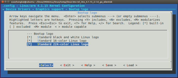
Figure 59.4.1.1 logo configuration items
The three options in figure 59.4.1.1 correspond to the logo in black-and-white, 16 bit and 24 bit color format respectively. We select all three and compile them into the Linux kernel. After setting, save and exit, recompile the Linux kernel, and start the system with the newly compiled imx6ull-alientek-emmc.dtb and zImage image image. If the LCD driver works normally, it will be on the LCD screen A colorful little penguin logo appears in the upper left corner of the screen, and the background color of the screen is black, as shown in figure 59.4.1.2:

Figure 59.4.1.2 Linux startup logo display
59.4.2 set LCD as terminal console
We always use SecureCRT as the terminal of the Linux development board, and the development board communicates with SecureCRT through the serial port. Now we have driven the LCD, so we can set the LCD as the terminal, that is, the development board uses its own display device as its own terminal, and then connect the keyboard to directly type commands on the development board and set the LCD as the side of the terminal console The method is as follows:
1. Setting bootargs in uboot
Restart the development board, enter the Linux command line, and reset the console content of the bootargs parameter. The command is as follows:
setenv bootargs 'console=tty1 console=ttymxc0,115200 root=/dev/nfs rw nfsroot=192.168.1.250:
/home/zuozhongkai/linux/nfs/rootfs ip=192.168.1.251:192.168.1.250:192.168.1.1:255.255.255.0::eth0:
off'
Note that the console is set in the red font. Here we set the console twice. For the first time, set the console=tty1, that is, set the LCD screen as the console. For the second time, set the console = ttymxc0115200, that is, set the serial port as the console. It is equivalent to opening two consoles, one is LCD and the other is serial port. Restart the development board and you will find the LCD and serial port The Linux startup log information will be displayed. However, we cannot use the LCD as the terminal for interaction at this time, because our settings have not been completed.
2. Modify the / etc/inittab file
Open the / etc/inittab file in the root file system of the development board and add the following line:
tty1::askfirst:-/bin/sh
The contents of the / etc/inittab file after adding are shown in figure 59.4.2.1:
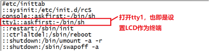
Figure 59.4.2.1 modified / etc/inittab file
After modification, save / etc/inittab and exit, and then restart the development board. After restart, the following line will be displayed on the last line of the LCD screen of the development board:
Please press Enter to activate this console.
The above prompt statement says: press the Enter KEY to enable the current terminal. In Chapter 58, we have registered the KEY on the I.MX6U-ALPHA development board as the Enter KEY, so press the KEY on the development board to enable the LCD terminal. Of course, you can also connect a USB keyboard. The Linux kernel has enabled the USB keyboard driver by default, so you can directly Use the USB keyboard.
So far, we have two sets of terminals, one is SecureCRT based on serial port, and the other is the LCD screen of our development board. However, in order to facilitate debugging, we will focus on SecureCRT in the future. We can output "hello linux" to the LCD screen through the following command line
echo hello linux > /dev/tty1
59.4.3 LCD backlight adjustment
As mentioned in section 59.3, the backlight device tree node has 8 levels of backlight adjustment, which can be set to 0 ~ 7. We can adjust the brightness of LCD backlight by setting the backlight level. Enter the following directory:
/sys/devices/platform/backlight/backlight/backlight
The files in this directory are shown in figure 59.4.3.1:
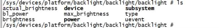
Figure 59.4.3.1 files and subdirectories under directory
Brightness in figure 59.4.3.1 represents the current brightness level and max_bgignness represents the maximum brightness level. The contents of these two files are shown in figure 59.4.3.2:
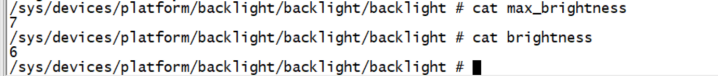
Figure 59.4.3.2 contents of brightness and max_brightness files
It can be seen from figure 59.4.3.2 that the current screen brightness level is 6. According to the previous analysis, this is 50% brightness. The maximum brightness level of the screen is 7. If we want to modify the screen brightness, we only need to write the screen brightness level to brightness. For example, if the screen brightness level is set to 7, you can use the following commands:
echo 7 > brightness
After entering the above command, you will find that the screen brightness increases. If brightness is set to 0, the LCD backlight will be turned off and the screen will go out.
59.4.4 solution of LCD automatic shutdown
By default, the LCD will turn off after 10 minutes. This is not a code problem, but set by the Linux kernel. Just like we use mobile phones or computers, if we don't operate for a period of time, the screen will turn off to save power. There are many ways to solve this problem. Let's look at it in turn:
1. Press the keyboard to wake up
The simplest is to press the Enter KEY to wake up the screen. In Chapter 58, we registered the KEY key on the I.MX6U-ALPHA development board as the Enter KEY, so press the KEY on the development board to wake up the screen. If there is no KEY on the development board, you can connect an external USB keyboard, and then press the Enter KEY on the USB keyboard to wake up the screen.
2. Turn off the screen shutdown function for 10 minutes
Find the drivers/tty/vt/vt.c file in the Linux source code, and find the blankinterval variable in this file, as shown below:
Example code 59.4.4.1 blankinterval variable
179 static int vesa_blank_mode;
180 static int vesa_off_interval;
181 static int blankinterval = 10*60;
blankinterval Variable control LCD The closing time is 10 by default*60,That's 10 minutes. take blankinterval Change the value of to 0 to turn off the screen shutdown function for 10 minutes. After modification, it needs to be recompiled Linux Kernel, get new zImage,Then use a new one zImage Launch the development board.
3,Write a APP To turn off the screen out function
 stay ubuntu Create a new one named lcd_always_on.c And then enter the following contents in it:
Example code 59.4.4.2 lcd_always_on.c File code snippet
1  #include <fcntl.h>
2  #include <stdio.h>
3  #include <sys/ioctl.h>
4
5
6  int main(int argc, char *argv[])
7  {
8      int fd;
9      fd = open("/dev/tty1", O_RDWR);
10     write(fd, "\033[9;0]", 8);
11     close(fd);
12     return 0;
13 }
Compile with the following command lcd_always_on.c This file:
arm-linux-gnueabihf-gcc lcd_always_on.c -o lcd_always_on
Compile and generate lcd_always_on, copy the executable file to the / usr/bin directory of the root file system of the development board, and then give the executable permission. Set LCD_ always_ The on software starts automatically after startup. Open / etc/init.d/rcS and add the following contents at the end of this file:
Example code 59.4.4.3 lcd_always_on Self start code
1 cd /usr/bin
2 ./lcd_always_on
3 cd ..
Save after modification/etc/init.d/rcS File, and then restart the development board. about Linux Lower LCD Let's stop here.