catalogue
2, Anonymous four axis host computer
2. Some simple protocols of software
3, Relevant receiving and sending codes
preface
For MCU developers, debugging tools are essential. Sometimes they need to display waveforms, send text, data and some complex data packets. For example, PID parameter tuning, however, all four axes have these functions. This paper introduces how anonymous four axis host computer displays waveform and debugging, as well as some receiving and sending codes.
1, What is the upper computer
Upper computer refers to the computer that can directly send control commands, generally PC/host computer/master computer/upper computer. Various signal changes (hydraulic pressure, water level, temperature, etc.) are displayed on the screen. Lower machine It is a computer that directly controls the equipment to obtain the equipment status, generally PLC/ singlechip single chip microcomputer/slave computer/lower computer and so on. The command sent by the upper computer is first given to the lower computer, and the lower computer interprets it into the corresponding command according to this command Timing signal Directly control the corresponding equipment. The lower computer reads the equipment status data (generally analog quantity) from time to time, converts it into digital signal and feeds it back to the upper computer. In short, the actual situation is very different, but everything changes: both upper and lower computers need programming and have special development systems.
Conceptually, the controller and the service provider are the upper computer, and the controlled and the served are the upper computer Lower machine , it can also be understood as the relationship between host and slave, but the upper computer and lower computer can be converted.
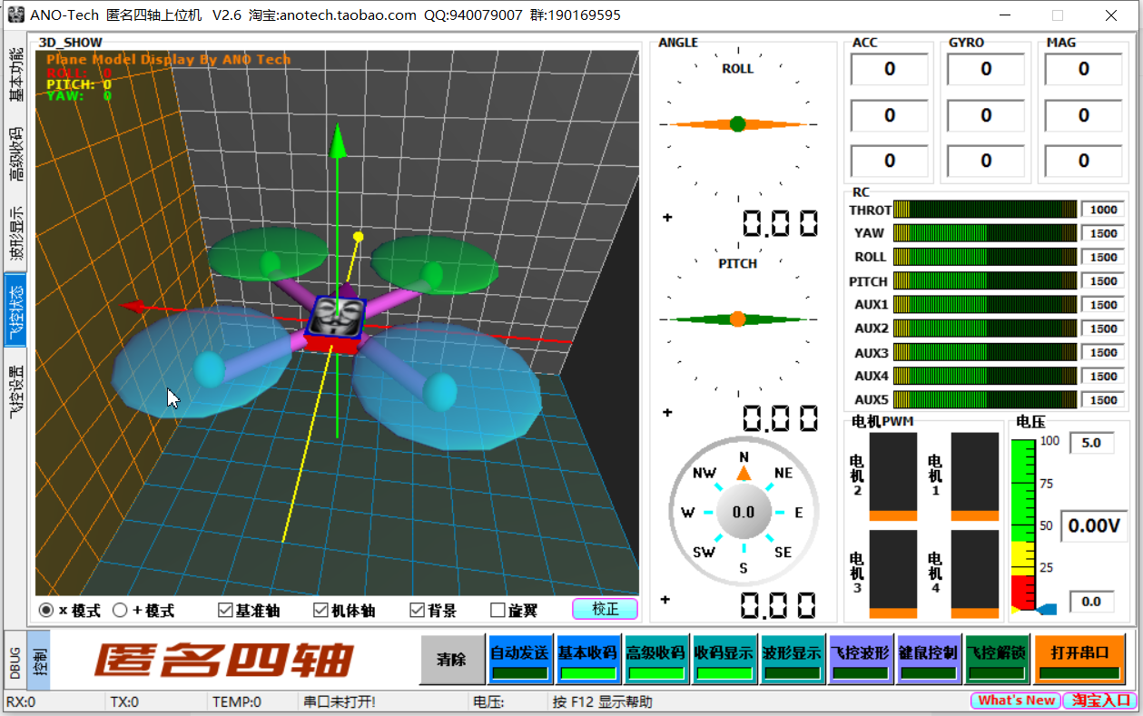
2, Anonymous four axis host computer
1. Function
The upper computer can basically send and receive (similar to the serial port debugging assistant), advanced send and receive codes (to realize complex custom receiving and sending), display 20 waveform diagrams at the same time (for debugging pid, etc.), debug the UAV, and monitor each state of the UAV and test the pid.
Four axis anonymous host computer download link:
http: / / link: https://pan.baidu.com/s/1l6kT-LQCMQRySXpp2lrh7w Extraction code: C5LQ
2. Some simple protocols of software
1: Basic transceiver
1: The receiving and sending formats can be set to HEX or CHR.
2: The timing sending function can be accurate to milliseconds, but not too fast (the sending is exclusive, and the function will not return until the data is sent). If the previous frame
Sending the next frame of data before sending the data will make an error.
3: Please use ft232 serial port chip or chip supporting high baud rate, otherwise the baud rate cannot be set too high.
2: Advanced code receiving
1: The receiving code is displayed in HEX format.
2: The lower computer sends user-defined data in the format of 0x88+FUN+LEN+DATA+SUM
FUN can be 0xA1 to 0xAA, 10 in total; LEN is the length of DATA (excluding 0x88, FUN, LEN and SUM).
SUM is the SUM from 0x88 to the last byte of DATA, in uint8 format.
(remember to turn on the switch to use the frame, change the setting and click Save to make the setting take effect)
3: The data can be in common formats such as uint8, int16, uint16, int32 and float, and the high bit of multi byte data comes first.
4: There are 20 data memories, and the data of each memory can be set to 30 data from 10 custom frames.
5: During high-speed communication (2ms one frame of data or faster), please turn off the data display button and basic code receiving on the advanced code receiving page, otherwise the update is too fast
Can cause the program to jam.
6: The corresponding frame FUN of flight control display is 0xAF, (frame format: 0x88+0xAF+0x1C+ACC DATA+GYRO DATA+MAG DATA+ANGLE DATA
+ 0x00 0x00 + 0x00 0x00+SUM, 32 bytes in total. ACC / hero / MAG / angle (roll / pitch / yaw) data is in int16 format
The roll and pitch data of ANGLE in is the integer value obtained by multiplying the actual value by 100, and yaw is the integer value obtained by multiplying 10,
The upper computer divides by 100 and 10 when displaying).
7: Remote control, motor pwm, voltage display, corresponding frame FUN is 0xAE, (frame format: 0x88 + 0xAE + 0x12 + thread yaw roll pitch
+ AUX1 2 3 4 5 + PWM:1 2 3 4 + VOTAGE + SUM, 28 bytes in total), the data is in uint16 format, and the minimum remote control data is about 1000,
The maximum is about 2000. The data are in uint16 format, in which the pwm range is 1-100 and the votage is the actual value * 100.
Tip: if the purpose of high-speed communication is to draw the waveform, only turn on the waveform display, and only keep the waveform to be observed. If it is to observe the number
According to, turn off the waveform display and only keep the code receiving display, which can speed up the response speed of the program.
7: The fastest communication speed has been tested. The lower computer uses 500K baud rate and sends 32 bytes of data every 1ms. The upper computer displays 6 waveforms. OK!
(it may be related to computer configuration)
3: Waveform display
1: There are 20 waveforms, corresponding to 20 data memories.
2: Double click the waveform drawing area to turn on the waveform display switch.
3: Hold down Ctrl and click a waveform with the left mouse button to display the data label. Click Hide again.
4: Press and hold the left mouse button, drag from one point to the right and down in the drawing area, and then release it to enlarge the framed waveform area, which can be placed multiple times
Large;
5: Hold down the left mouse button, drag from one point to the upper left in the drawing area, and then release to restore the amplified waveform.
6: Hold down the right mouse button and drag up, down, left and right in the drawing area to move the waveform.
7: When the waveform is displayed, press F9 to open the advanced waveform setting.
4: DEBUG function
1: During debugging, some flag bits, registers and variables can be sent back to the upper computer in real time and displayed on the DEBUG page.
2: The communication format is 0x88 + 0xAD + len + num + DATA + SUM, Len is the total length of num and DATA, and num indicates which display to change
For example, num=0x01 is to change the first LED, and num=0x07 is to change the first digital output display. When you want to change the LED,
DATA only needs one byte. DATA=0x00 means to turn off the LED, and greater than 0x00 means to turn on the LED; When changing the digital output, DATA needs two words
Festival,
Represents a uint16 number, with the high byte first. SUM is the SUM check from 0x88 to the previous byte of SUM, in uint8 format.
For example: send 0x88 + 0xAD + 0x02 + 0x01 + 0x01 + 0x39 Indicates that the first LED is lit
Send 0x88 + 0xAD + 0x03 + 0x07 + 0x00 + 0x05 + 0x44 Indicates that 5 is displayed at the first digital output position.
5: Keyboard and mouse control
1: Control data sending format: 0x8a + 0x8a + 0x1c + thread yaw roll pitch AUX1 aux2 aux3 aux4 aux5 + 0x00 0x00
0x00 0x00 0x00 0x00 0x00 0x00 0x00 0x00 0x00 + SUM, the remote control data are in int16 format, the median value is 1500, the minimum and maximum value is 1000
2000.
2: The transmission frequency is 50Hz.
3: The mouse controls the throttle up and down, the left and right controls YAW, the WASD of the keyboard controls ROLL/PITCH, and the 12345 of the keyboard controls AUX12345. 9 channels in total.
6: Flight control parameters
1: Click the correction button at the bottom right of the 3D model display, and the upper machine sends 0X8A 0X8B 0X1C 0XAA 0XA3 + useless data + SUM to the lower machine,
Among them, 0X8B represents flight control parameters, 0XAA represents zero bias, 0XA3 represents ACC, and gyro must be corrected.
2: Click the correction button in the sensor correction function in the flight control parameter interface to indicate the correction of ACC and GYRO respectively, and the two sensors will not be corrected at the same time
Device,
The sending format of ACC corrected by the upper computer is: 0X8A 0X8B 0X1C 0XAA 0XA1 + useless data + SUM
The sending format of GYRO corrected by the upper computer is: 0X8A 0X8B 0X1C 0XAA 0XA2 + useless data + SUM (the whole length of the sent data is 32 bytes)
3: The host computer sends the offset data after fine adjustment (only x and y of ACC) in the format of 0x8a, 0x8b, 0x1c, 0xab + offset. X + offset. Y
+ Useless data + SUM, data in int16 format.
4: The format of the command sent by the upper computer to read offset is: 0X8A 0X8B 0X1C 0XAC + useless data + SUM
5: The command sent by the upper computer to read PID data is: 0x8a, 0x8b, 0x1c, 0xad + useless data + SUM
6: The format of the offset data sent by the lower computer to the upper computer is: 0X88 0XAC 0X1C 0XAC + sensor zero bias data ACC XYZ GYRO XYZ
+ Useless data + SUM, a total of six int16 data.
7: The format of PID data sent by the lower computer to the upper computer is: 0X88 0XAC 0X1C 0XAD + PID data + useless data + SUM
PID data is rol_ p,rol_ i,rol_ d,pit_ p..i..d,yaw_ p. , I,, D, 9 uint16 data in total.
8: The format of PID data sent by the upper computer to the lower computer is: 0x8a, 0x8b, 0x1c, 0xae + PID data + useless data + SUM
The format of PID data is the same as that sent by the lower computer to the upper computer.
9: Click the flight control unlock button, and the upper machine will send 0X8A 0X8B 0X1C 0XA1 + useless data + SUM to the lower machine. If the lower machine has been unlocked,
Clicking this button will send 0X8A 0X8B 0X1C 0XA0 + useless data + SUM to the lower computer to lock the flight control.
3, Relevant receiving and sending codes
1, Receive data
1. Receive data stream
If the received packet is sent according to the protocol, the data is stored in Rx_ In the upcomputer array.
//Data reception
#define E_ Start 0 / / preparation succeeds
#define E_ OK 1. / / success
#define E_ FRAME_ HEADER_ Error 2 / / frame header error
#define E_ FRAME_ RTAIL_ Error 3 / / end of frame error
#define LINE_ LIN_ Up 32 / / data length
uint8_t uart_flag_up;                     //Receive flag

vu8 RX_upcomputer[33];
void get_upcomputer_data(uint8_t data)
{
	static uint8_t uart_num=0;
	vu8 sum=0;
    vu8 i=0;
    RX_upcomputer[uart_num++]=data;
    if(1==uart_num)
    {
        //The first byte received is not 0X8A, frame header error
        if(0X8A!=RX_upcomputer[0])
        {
            uart_num=0;
            uart_flag_up=E_FRAME_HEADER_ERROR;
        }
    }
		if(2==uart_num)
    {
        //The second byte received is not 0x8B, frame header error
        if(0X8B!=RX_upcomputer[1])
        {
            uart_num=0;
            uart_flag_up=E_FRAME_HEADER_ERROR;
        }
    }
		if(3==uart_num)
    {
        //The third byte received is not 0X1C, frame header error
        if(0X1C!=RX_upcomputer[2])
        {
            uart_num=0;
            uart_flag_up=E_FRAME_HEADER_ERROR;
        }
    }

    if(LINE_LIN_up==uart_num)
    {
        uart_flag_up=E_OK;
        //The last byte received is the check bit
			for(i=0;i<LINE_LIN_up-1;i++)
			sum += RX_upcomputer[i];        //Check bit

        if(sum==RX_upcomputer[LINE_LIN_up-1])
            uart_flag_up=E_OK;
        else                                //Check bit error of the last byte received, end of frame error
            uart_flag_up=E_FRAME_RTAIL_ERROR;
        uart_num=0;
    }

}
2. Analyze data
Analytic existence RX_ Data in the upcomputer array.
extern float Out_XP,Out_XI,Out_XD,In_XP,In_XI,In_XD,Out_YP,Out_YI,Out_YD,In_YP,In_YI,In_YD,ZP,ZI,ZD;
extern float out_zp;
//Analyzing the pid data sent by the host computer
void upcomputer_receive1(void)
{

	In_XP=((int)RX_upcomputer[4]<<8)|RX_upcomputer[5];
	In_XP=In_XP/100;
	In_XI=((int)RX_upcomputer[6]<<8)|RX_upcomputer[7];
	In_XI=In_XI/100;
	In_XD=((int)RX_upcomputer[8]<<8)|RX_upcomputer[9];
	In_XD=In_XD/100;
	out_zp=((int)RX_upcomputer[10]<<8)|RX_upcomputer[11];
	out_zp=out_zp/100;
	In_YI=((int)RX_upcomputer[12]<<8)|RX_upcomputer[13];
	In_YI=In_YI/100;
	In_YD=((int)RX_upcomputer[14]<<8)|RX_upcomputer[15];
	In_YD=In_YD/100;
	ZP=((int)RX_upcomputer[16]<<8)|RX_upcomputer[17];
	ZP=ZP/100;
	ZI=((int)RX_upcomputer[18]<<8)|RX_upcomputer[19];
	ZI=ZI/100;
	ZD=((int)RX_upcomputer[20]<<8)|RX_upcomputer[21];
	ZD=ZD/100;
}


//Analyze the offset after fine adjustment of the upper computer
int offset_x,offset_y;
void upcomputer_receive2(void)
{
	offset_x=((int)RX_upcomputer[4]<<8)|RX_upcomputer[5];

	offset_y=((int)RX_upcomputer[6]<<8)|RX_upcomputer[7];

}
2. Send data
void usart1_SendByte(u8 data)
{
    /* Send byte data to UART */
    USART_SendData(USART1,data);

    /*The waiting to send register is empty */
    while (USART_GetFlagStatus(USART1, USART_FLAG_TXE) == RESET);
}

/****************** Send octet array************************/
void usart1_SendArray(vu8 *array, uint16_t num)
{
    vu8 i;

  for(i=0; i<num; i++)
  {
        /* ·Send a byte of data to USART */
     usart1_SendByte(array[i]);
  }
    /* Wait for sending to complete */
  while(USART_GetFlagStatus(USART1,USART_FLAG_TC)==RESET);
}


vu8 testdatatosend[50];
/*Waveform display function*/
void Test_Send_User(uint16_t data1, uint16_t data2, uint16_t data3,uint16_t data4,uint16_t data5,uint16_t data6,uint16_t data7,uint16_t data8,uint16_t data9,uint16_t data10)
{
    vu8 _cnt=0;
    vu8 sum=0;
    vu8 i=0;

    testdatatosend[_cnt++]=0x88;
    testdatatosend[_cnt++]=0xA1;
    testdatatosend[_cnt++]=0;

    testdatatosend[_cnt++]=data1>>8;
    testdatatosend[_cnt++]=data1&0xff;

    testdatatosend[_cnt++]=data2>>8;
    testdatatosend[_cnt++]=data2&0xff;

    testdatatosend[_cnt++]=data3>>8;
    testdatatosend[_cnt++]=data3&0xff;

    testdatatosend[_cnt++]=data4>>8;
    testdatatosend[_cnt++]=data4&0xff;

    testdatatosend[_cnt++]=data5>>8;
    testdatatosend[_cnt++]=data5&0xff;

    testdatatosend[_cnt++]=data6>>8;
    testdatatosend[_cnt++]=data6&0xff;

    testdatatosend[_cnt++]=data7>>8;
    testdatatosend[_cnt++]=data7&0xff;

    testdatatosend[_cnt++]=data8>>8;
    testdatatosend[_cnt++]=data8&0xff;

    testdatatosend[_cnt++]=data9>>8;
    testdatatosend[_cnt++]=data9&0xff;

    testdatatosend[_cnt++]=data10>>8;
    testdatatosend[_cnt++]=data10&0xff;


    testdatatosend[2] = _cnt-3;

    for(i=0;i<_cnt;i++)
        sum += testdatatosend[i];

    testdatatosend[_cnt++]=sum;

    usart1_SendArray(testdatatosend,_cnt);
}


/*****************************************************************************************
*The following functions are mainly used for UAV debugging and other pid debugging
*
***************************************************************************************/

/*Send gyroscope data to upper computer*/
void Test_Send_User1(int16_t acc_x_,int16_t acc_y_,int16_t acc_z_,int16_t gyro_x_,int16_t gyro_y_,int16_t gyro_z_,int16_t roll_,int16_t pitch_,int16_t yaw_)
{
	 vu8 _cnt=0;
    vu8 sum=0;
    vu8 i=0;

    testdatatosend[_cnt++]=0x88;
    testdatatosend[_cnt++]=0xAF;
    testdatatosend[_cnt++]=0x1C;

    testdatatosend[_cnt++]=acc_x_>>8;     //
    testdatatosend[_cnt++]=acc_x_&0xff;   //

    testdatatosend[_cnt++]=acc_y_>>8;
    testdatatosend[_cnt++]=acc_y_&0xff;

    testdatatosend[_cnt++]=acc_z_>>8;
    testdatatosend[_cnt++]=acc_z_&0xff;

    testdatatosend[_cnt++]=gyro_x_>>8;
    testdatatosend[_cnt++]=gyro_x_&0xff;

    testdatatosend[_cnt++]=gyro_y_>>8;
    testdatatosend[_cnt++]=gyro_y_&0xff;

    testdatatosend[_cnt++]=gyro_z_>>8;
    testdatatosend[_cnt++]=gyro_z_&0xff;

		testdatatosend[_cnt++]=0;
		testdatatosend[_cnt++]=0;

		testdatatosend[_cnt++]=0;
		testdatatosend[_cnt++]=0;

		testdatatosend[_cnt++]=0;
		testdatatosend[_cnt++]=0;

    testdatatosend[_cnt++]=roll_>>8;
    testdatatosend[_cnt++]=roll_&0xff;

    testdatatosend[_cnt++]=pitch_>>8;
    testdatatosend[_cnt++]=pitch_&0xff;

    testdatatosend[_cnt++]=yaw_>>8;
    testdatatosend[_cnt++]=yaw_&0xff;

    testdatatosend[_cnt++]=0x00;
    testdatatosend[_cnt++]=0x00;
		testdatatosend[_cnt++]=0x00;
    testdatatosend[_cnt++]=0x00;

    testdatatosend[2] = _cnt-3;

    for(i=0;i<_cnt;i++)
        sum += testdatatosend[i];

    testdatatosend[_cnt++]=sum;

    usart1_SendArray(testdatatosend,_cnt);

}


/*Send motor pwm and flight control battery voltage to the upper computer*/
void Test_Send_User2(uint16_t throt,uint16_t yaw_2,uint16_t roll_2,uint16_t pitch_2,uint16_t aux_1,uint16_t aux_2,uint16_t aux_3,uint16_t aux_4,uint16_t aux_5,uint16_t pwm1,uint16_t pwm2,uint16_t pwm3,uint16_t pwm4,uint16_t votage)
{

	vu8 _cnt=0;
    vu8 sum=0;
    vu8 i=0;

    testdatatosend[_cnt++]=0x88;
    testdatatosend[_cnt++]=0xAE;
    testdatatosend[_cnt++]=0x12;

	  testdatatosend[_cnt++]=throt>>8;
    testdatatosend[_cnt++]=throt&0xff;

    testdatatosend[_cnt++]=yaw_2>>8;     //
    testdatatosend[_cnt++]=yaw_2&0xff;   //

    testdatatosend[_cnt++]=roll_2>>8;
    testdatatosend[_cnt++]=roll_2&0xff;

    testdatatosend[_cnt++]=pitch_2>>8;
    testdatatosend[_cnt++]=pitch_2&0xff;

    testdatatosend[_cnt++]=aux_1>>8;
    testdatatosend[_cnt++]=aux_1&0xff;

    testdatatosend[_cnt++]=aux_2>>8;
    testdatatosend[_cnt++]=aux_2&0xff;

    testdatatosend[_cnt++]=aux_3>>8;
    testdatatosend[_cnt++]=aux_3&0xff;

    testdatatosend[_cnt++]=aux_4>>8;
    testdatatosend[_cnt++]=aux_4&0xff;

    testdatatosend[_cnt++]=aux_5>>8;
    testdatatosend[_cnt++]=aux_5&0xff;

    testdatatosend[_cnt++]=pwm1>>8;
		testdatatosend[_cnt++]=pwm1&0xff;

    testdatatosend[_cnt++]=pwm2>>8;
		testdatatosend[_cnt++]=pwm2&0xff;

    testdatatosend[_cnt++]=pwm3>>8;
		testdatatosend[_cnt++]=pwm3&0xff;

    testdatatosend[_cnt++]=pwm4>>8;
		testdatatosend[_cnt++]=pwm4&0xff;

		testdatatosend[_cnt++]=votage>>8;
    testdatatosend[_cnt++]=votage&0xff;

    testdatatosend[2] = _cnt-3;

    for(i=0;i<_cnt;i++)
        sum += testdatatosend[i];

    testdatatosend[_cnt++]=sum;

    usart1_SendArray(testdatatosend,_cnt);

}


/*Send OFFSET to upper computer*/
void Test_Send_User3(int16_t acc_x_3,int16_t acc_y_3,int16_t acc_z_3,int16_t gyro_x_3,int16_t gyro_y_3,int16_t gyro_z_3)
{
	vu8 _cnt=0;
    vu8 sum=0;
    vu8 i=0;

    testdatatosend[_cnt++]=0x88;
    testdatatosend[_cnt++]=0xAC;
    testdatatosend[_cnt++]=0x1C;
	  testdatatosend[_cnt++]=0xAC;

	  testdatatosend[_cnt++]=acc_x_3>>8;
    testdatatosend[_cnt++]=acc_x_3&0xff;

    testdatatosend[_cnt++]=acc_y_3>>8;     //
    testdatatosend[_cnt++]=acc_y_3&0xff;   //

    testdatatosend[_cnt++]=acc_z_3>>8;
    testdatatosend[_cnt++]=acc_z_3&0xff;

    testdatatosend[_cnt++]=gyro_x_3>>8;
    testdatatosend[_cnt++]=gyro_x_3&0xff;

    testdatatosend[_cnt++]=gyro_y_3>>8;
    testdatatosend[_cnt++]=gyro_y_3&0xff;

    testdatatosend[_cnt++]=gyro_z_3>>8;
    testdatatosend[_cnt++]=gyro_z_3&0xff;

    //testdatatosend[2] = _cnt-3;

    for(i=0;i<_cnt;i++)
        sum += testdatatosend[i];

    testdatatosend[31]=sum;

    usart1_SendArray(testdatatosend,32);


}


//Send PID parameters to the upper computer*/
void Test_Send_User4(uint16_t rol_p,uint16_t rol_i,uint16_t rol_d,uint16_t pit_p,uint16_t pit_i,uint16_t pit_d,uint16_t yaw_p,uint16_t yaw_i,uint16_t yaw_d)
{
	vu8 _cnt=0;
    vu8 sum=0;
    vu8 i=0;

    testdatatosend[_cnt++]=0x88;
    testdatatosend[_cnt++]=0xAC;
    testdatatosend[_cnt++]=0x1C;
	  testdatatosend[_cnt++]=0xAD;

	  testdatatosend[_cnt++]=rol_p>>8;
    testdatatosend[_cnt++]=rol_p&0xff;

    testdatatosend[_cnt++]=rol_i>>8;     //
    testdatatosend[_cnt++]=rol_i&0xff;   //

    testdatatosend[_cnt++]=rol_d>>8;
    testdatatosend[_cnt++]=rol_d&0xff;

    testdatatosend[_cnt++]=pit_p>>8;
    testdatatosend[_cnt++]=pit_p&0xff;

    testdatatosend[_cnt++]=pit_i>>8;
    testdatatosend[_cnt++]=pit_i&0xff;

    testdatatosend[_cnt++]=pit_d>>8;
    testdatatosend[_cnt++]=pit_d&0xff;

    testdatatosend[_cnt++]=yaw_p>>8;
    testdatatosend[_cnt++]=yaw_p&0xff;

    testdatatosend[_cnt++]=yaw_i>>8;
    testdatatosend[_cnt++]=yaw_i&0xff;

    testdatatosend[_cnt++]=yaw_d>>8;
    testdatatosend[_cnt++]=yaw_d&0xff;

   // testdatatosend[2] = _cnt-3;

    for(i=0;i<_cnt;i++)
        sum += testdatatosend[i];

    testdatatosend[31]=sum;

    usart1_SendArray(testdatatosend,32);


}
summary
The above is today's content, the use of four axis anonymous host computer, protocol and some receiving and sending codes.
This is the summary of my study. If there is anything wrong, please point it out.