SAADC - successive approximation analog-to-digital converter
ADC is a differential successive approximation register (SAR) analog-to-digital converter.
The following are the main features of SAADC:
- 8 / 10 / 12 bit resolution, 14 bit resolution with oversampling
- Up to 8 input channels
- One channel for single ended input and two channels for differential input
- Single ended channel and differential channel can be configured in scanning mode.
- Full scale input range (0 to VDD)
- Trigger sampling through the task of software or PPI channel to fully flexible sampling frequency source, from low-power 32.768kHz RTC or more accurate 1/16MHz timer
- One time conversion mode, sampling single channel
- Scan mode, sampling a series of channels in sequence. The sampling delay between channels is s tack + tconv. The delay between channels will vary according to the user's stack configuration. • It supports the direct transfer of samples to RAM using EasyDMA
- Interrupt on single sample and full buffer events
- For differential and single ended sampling, the samples are stored as 16 bit 2 complements
- Continuous sampling without external timer
- Internal resistance string
- Limit hasty inspection
shared resource
ADC can coexist with COMP and other peripherals using one of AIN0-AIN7 as long as these are assigned to different pins.
It is not recommended that both modules select the same analog input pin.
overview
The ADC supports up to 8 external analog input channels, depending on the package variant. It can
Operate in one sampling mode under software control or continuous conversion mode with programmable sampling rate.
Analog inputs can be configured as 8 single ended inputs, 4 differential inputs, or a combination of these. Each channel can be configured to select AIN0 ~ AIN7 pins or VDD pins. Channels can be sampled individually in single or continuous sampling mode, or multiple channels can be sampled sequentially using scan mode. The channel can also be oversampled to improve noise performance.
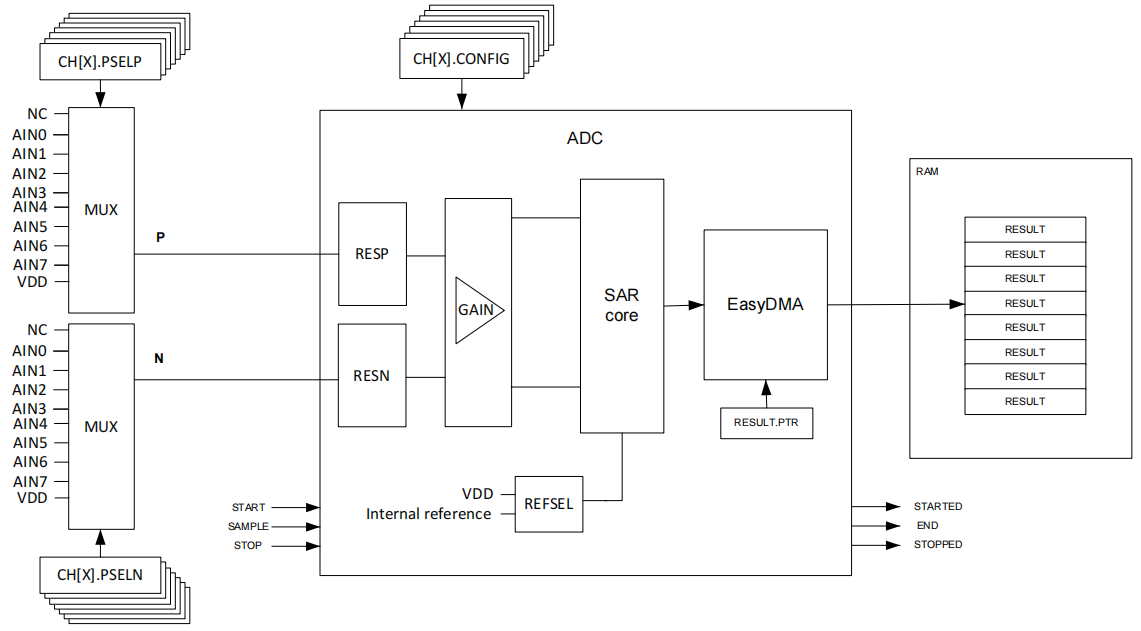
Figure 98: simplified ADC block diagram
Internally, ADC is always a differential analog-to-digital converter, but by default, it is configured as a single ended input in the MODE field of CH[n]. Configuration register. In single ended MODE, the negative input will be internally shorted to ground.
The assumption in single ended mode is that the internal ground of ADC is the same as the external ground referenced by the measured voltage. Therefore, the ADC is very sensitive to the ground bounce on the PCB in single ended mode. If this is a problem, we recommend using differential measurement.
EasyDMA
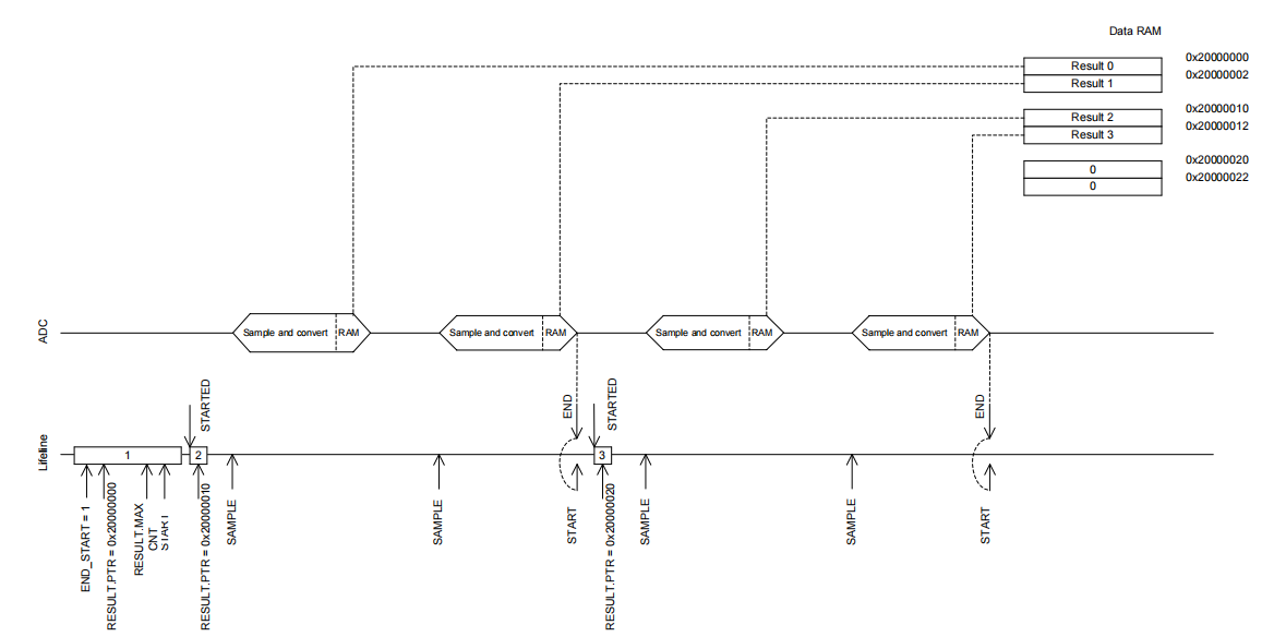
Results after configuration. PTR and results. MAXCNT starts ADC resources by triggering the START task. ADC uses EasyDMA to store the results in the Result buffer of RAM.
The Result buffer is located at the address specified in the Result. PTR registration. Result. The PTR register is double buffered and can be updated immediately after the START event is generated and ready for the next START task. The size of the Result buffer is specified in the Result. When the MAXCNT register and ADC fill the Result buffer, an END event is generated, see Figure 101:ADC on page 362. The results are stored in the data RAM in small END byte order. Each sample will be symbol extended to 16 bits and stored in the Result buffer.
STOP the ADC by triggering the STOP task. The STOP task terminates the sampling in progress. When the ADC stops, a stopped event is generated. If the ADC has stopped when the STOP task is triggered, the stopped event will still be generated.
If RESULT.PTR does not point to the Data RAM area, an EasyDMA transfer may cause HardFault or ram damage. For more information about different memory regions, see memory on page 23. When the END or STOPPED event is generated, EasyDMA will complete the access to ram.
RESULT.AMOUNT can read the AMOUNT register after the END event or STOPPED event to see how many results have been transferred to the result buffer in RAM since the START task was triggered. In Scan mode, the size of the result buffer must be large enough to have enough space to accommodate at least one result from each enabled channel. To ensure this, the results. MAXCNT must be specified as result. MAXCNT > = "number of channels enabled". For more information, see Scan mode on page 360 about Scan mode.
/********************************************************************************
* @file    bsp_adc.c
* @author  jianqiang.xue
* @version V1.0.0
* @date    2021-07-06
* @brief   ADC Operation reference: https://blog.csdn.net/polaris_zgx/article/details/80405334
********************************************************************************/

/* Includes ------------------------------------------------------------------*/
#include "RTE_Components.h"
#include CMSIS_device_header

#include "nrf_drv_saadc.h"
#include "sdk_errors.h"

#include "bsp_gpio.h"
#include "bsp_exti.h"
#include "bsp_adc.h"

/* Private Includes ----------------------------------------------------------*/
#include "business_gpio.h"
#include "business_function.h"

/* Private Define ------------------------------------------------------------*/
#define ADC0_CH_NUM                   8

#define ADC0_CH0                      0
#define ADC0_CH1                      1
#define ADC0_CH2                      2
#define ADC0_CH3                      3
#define ADC0_CH4                      4
#define ADC0_CH5                      5
#define ADC0_CH6                      6
#define ADC0_CH7                      7

#define CH_NUM  (BS_ADC0_CH0 + BS_ADC0_CH1 + BS_ADC0_CH2 + BS_ADC0_CH3 + BS_ADC0_CH4 + BS_ADC0_CH5 + BS_ADC0_CH6 + BS_ADC0_CH7)
/* Private Variables ---------------------------------------------------------*/
// ADC initialization status (0--deinit 1--init)
static bool g_adc_init = false;
// ADC acquisition data storage buff
uint16_t bsp_adc0_val[ADC0_CH_NUM] = {0};
uint16_t bsp_adc0_temp_val[CH_NUM] = {0};
// Define ADC collection completion callback function
typedef void(*bsp_adc0_callback)(void);
static bsp_adc0_callback irq_callback;

/* External Variables --------------------------------------------------------*/
/* Private Function Prototypes -----------------------------------------------*/
#if BS_ADC0_EN
/**
 * @brief  Reorder the values collected by the ADC to another array
 * @note   NULL
 * @retval None
 */
static void bsp_adc0_val_copy(void)
{
    uint8_t num = 0;
    bool flag = false;

    for (uint8_t i = 0; i < ADC0_CH_NUM; i++)
    {
        if (i == ADC0_CH0 && BS_ADC0_CH0)
        {
            flag = true;
        }
        else if(i == ADC0_CH1 && BS_ADC0_CH1)
        {
            flag = true;
        }
        else if(i == ADC0_CH2 && BS_ADC0_CH2)
        {
            flag = true;
        }
        else if(i == ADC0_CH3 && BS_ADC0_CH3)
        {
            flag = true;
        }
        else if(i == ADC0_CH4 && BS_ADC0_CH4)
        {
            flag = true;
        }
        else if(i == ADC0_CH5 && BS_ADC0_CH5)
        {
            flag = true;
        }
        else if(i == ADC0_CH6 && BS_ADC0_CH6)
        {
            flag = true;
        }
        else if(i == ADC0_CH7 && BS_ADC0_CH7)
        {
            flag = true;
        }
        if (flag)
        {
            flag = false;
            bsp_adc0_val[i] = bsp_adc0_temp_val[num];
            num++;
            if (num == CH_NUM)
            {
                break;
            }
        }
    }
}

/**
 * @brief ADC interrupt handler.
 */
static void saadc_callback(nrf_drv_saadc_evt_t const * p_event)
{
    if (p_event->type == NRF_DRV_SAADC_EVT_DONE)
    {
        bsp_adc0_val_copy();
        nrf_drv_saadc_buffer_convert(p_event->data.done.p_buffer, CH_NUM);
        if (irq_callback)
        {
            irq_callback();
        }
    }
}

/* Public Function Prototypes ------------------------------------------------*/
/**
 * @brief  ADC0 Initialize and enable the channel
 * @note   NULL
 * @retval None
 */
void bsp_adc0_init(void)
{
#if CH_NUM > 0
    if (g_adc_init)
    {
        return;
    }
    nrf_drv_saadc_config_t saadc_config = NRF_DRV_SAADC_DEFAULT_CONFIG;
    saadc_config.resolution = NRF_SAADC_RESOLUTION_12BIT;
    uint32_t err_code;

    err_code = nrf_drv_saadc_init(&saadc_config, saadc_callback);
    APP_ERROR_CHECK(err_code);
#if BS_ADC0_CH0
    nrf_saadc_channel_config_t channel_0_config = NRF_DRV_SAADC_DEFAULT_CHANNEL_CONFIG_SE(NRF_SAADC_INPUT_AIN0);
    err_code = nrfx_saadc_channel_init(ADC0_CH0, &channel_0_config);
    APP_ERROR_CHECK(err_code);
#endif
#if BS_ADC0_CH1
    nrf_saadc_channel_config_t channel_1_config = NRF_DRV_SAADC_DEFAULT_CHANNEL_CONFIG_SE(NRF_SAADC_INPUT_AIN1);
    err_code = nrfx_saadc_channel_init(ADC0_CH1, &channel_1_config);
    APP_ERROR_CHECK(err_code);
#endif
#if BS_ADC0_CH2
    nrf_saadc_channel_config_t channel_2_config = NRF_DRV_SAADC_DEFAULT_CHANNEL_CONFIG_SE(NRF_SAADC_INPUT_AIN2);
    err_code = nrfx_saadc_channel_init(ADC0_CH2, &channel_2_config);
    APP_ERROR_CHECK(err_code);
#endif
#if BS_ADC0_CH3
    nrf_saadc_channel_config_t channel_3_config = NRF_DRV_SAADC_DEFAULT_CHANNEL_CONFIG_SE(NRF_SAADC_INPUT_AIN3);
    err_code = nrfx_saadc_channel_init(ADC0_CH3, &channel_3_config);
    APP_ERROR_CHECK(err_code);
#endif
#if BS_ADC0_CH4
    nrf_saadc_channel_config_t channel_4_config = NRF_DRV_SAADC_DEFAULT_CHANNEL_CONFIG_SE(NRF_SAADC_INPUT_AIN4);
    err_code = nrfx_saadc_channel_init(ADC0_CH4, &channel_4_config);
    APP_ERROR_CHECK(err_code);
#endif
#if BS_ADC0_CH5
    nrf_saadc_channel_config_t channel_5_config = NRF_DRV_SAADC_DEFAULT_CHANNEL_CONFIG_SE(NRF_SAADC_INPUT_AIN5);
    err_code = nrfx_saadc_channel_init(ADC0_CH5, &channel_5_config);
    APP_ERROR_CHECK(err_code);
#endif
#if BS_ADC0_CH6
    nrf_saadc_channel_config_t channel_6_config = NRF_DRV_SAADC_DEFAULT_CHANNEL_CONFIG_SE(NRF_SAADC_INPUT_AIN6);
    err_code = nrfx_saadc_channel_init(ADC0_CH6, &channel_6_config);
    APP_ERROR_CHECK(err_code);
#endif
#if BS_ADC0_CH7
    nrf_saadc_channel_config_t channel_7_config = NRF_DRV_SAADC_DEFAULT_CHANNEL_CONFIG_SE(NRF_SAADC_INPUT_AIN7);
    err_code = nrfx_saadc_channel_init(ADC0_CH7, &channel_7_config);
    APP_ERROR_CHECK(err_code);
#endif
    err_code = nrf_drv_saadc_buffer_convert((nrf_saadc_value_t *)(bsp_adc0_temp_val), CH_NUM);
    APP_ERROR_CHECK(err_code);
    g_adc_init = true;
#endif
}

/**
 * @brief  ADC0 The function is turned off and removed
 * @note   NULL
 * @retval None
 */
void bsp_adc0_deinit(void)
{
#if CH_NUM > 0
    if (!g_adc_init)
    {
        return;
    }
    nrf_drv_saadc_uninit();
    g_adc_init = false;
#endif
}

/**
 * @brief  ADC0 Start sampling function
 * @note   NULL
 * @retval None
 */
void bsp_adc0_start(void)
{
#if CH_NUM
    if (!g_adc_init)
    {
        return;
    }
    APP_ERROR_CHECK(nrfx_saadc_sample());
#endif
}

#else
void bsp_adc0_init(void)
{
}

void bsp_adc0_deinit(void)
{
}

void bsp_adc0_start(void)
{
}
#endif

/**
 * @brief  Get ADC0 sampling value
 * @note   NULL
 * @param  ch_num: Channel value
 * @retval ADC value corresponding to the channel
 */
uint16_t bsp_adc0_get_ch_val(uint8_t ch_num)
{
    if (ch_num >= ADC0_CH_NUM)
    {
        return 0xFFFF;
    }
    return bsp_adc0_val[ch_num];
}

/**
 * @brief  Register ADC0 sampling completion callback function
 * @note   NULL
 * @param  *event: Bind callback event
 * @retval 0--Failure 1 -- success
 */
bool bsp_adc0_irq_callback(void *event)
{
    if (irq_callback != NULL)
    {
        return false;
    }
    else
    {
        irq_callback = (bsp_adc0_callback)event;
    }
    return true;
}
/********************************************************************************
* @file    bsp_adc.h
* @author  jianqiang.xue
* @version V1.0.0
* @date    2021-04-10
* @brief   ADC operation
********************************************************************************/

#ifndef __BSP_ADC_H
#define __BSP_ADC_H

/* Includes ------------------------------------------------------------------*/
#include <stdint.h>
#include <stdbool.h>

/* Public Function Prototypes -----------------------------------------------*/

void bsp_adc0_init(void);
void bsp_adc0_deinit(void);

void bsp_adc0_start(void);

uint16_t bsp_adc0_get_ch_val(uint8_t ch_num);

bool bsp_adc0_irq_callback(void *event);

#endif
Official Manual Download:
https://infocenter.nordicsemi.com/pdf/nRF52810_PS_v1.3.pdf
https://infocenter.nordicsemi.com/pdf/nRF52820_PS_v1.2.pdf
https://infocenter.nordicsemi.com/pdf/nRF52832_PS_v1.7.pdf
https://infocenter.nordicsemi.com/pdf/nRF52840_PS_v1.5.pdf