1, Interrupt mode programming
One pin of the GPIOA end of the stm32F103 core board is connected to an LED, and one pin of the GPIOB port is connected to a switch (replaced by DuPont line simulation). Interrupt mode programming is adopted. When the switch is connected to high level, the LED lights up; When connected to low level, the LED is off.
1.cubeMX create project
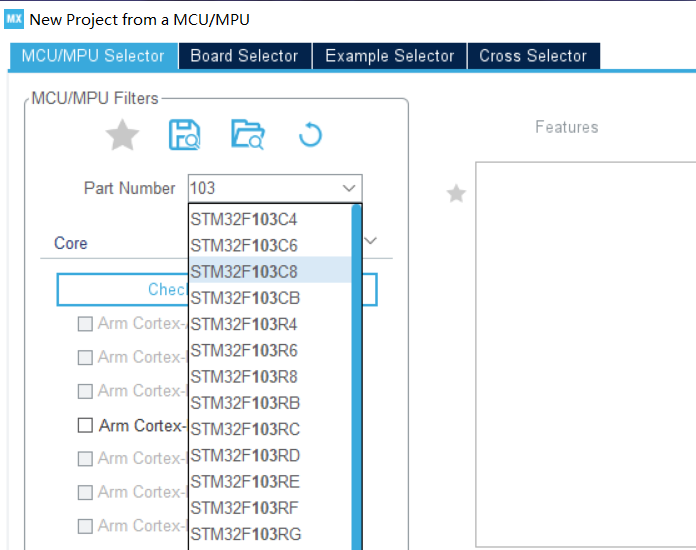
Select stm32f103c8 chip to create project
Select pin
exit configuration
sys is set to serial write
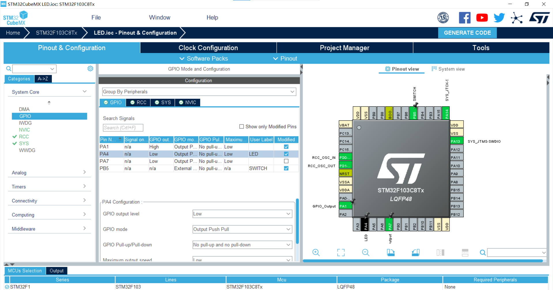
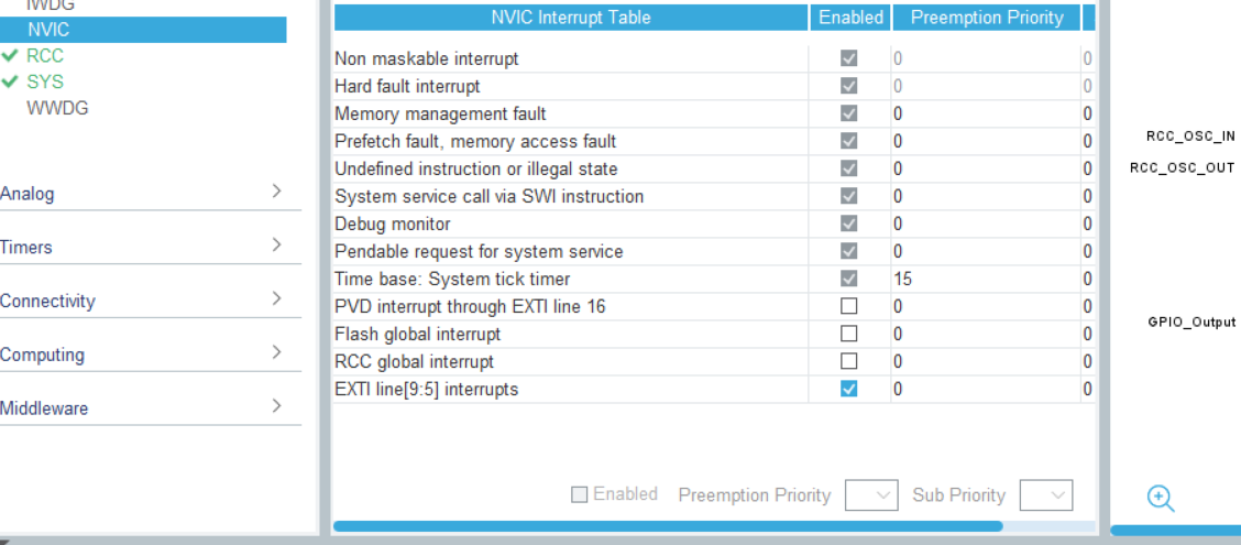
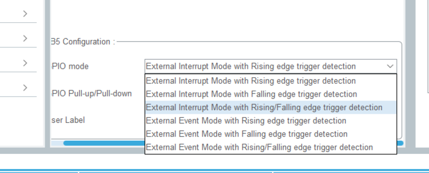
gpioexit pin settings are shown in the figure below
Create project
2.keil code modification
Via stm32f1xx_ Exti9 in it. C file_ 5_ The irqhandler function f12 jumps to stm32f1xx_ hal_ The GPIO. C file found HAL_GPIO_EXTI_Callback function and modify
(only f12 jump after compilation)
code:
    void HAL_GPIO_EXTI_Callback(uint16_t GPIO_Pin){
      if(GPIO_Pin == SWITCH_Pin){
        GPIO_PinState pinState = HAL_GPIO_ReadPin(SWITCH_GPIO_Port,SWITCH_Pin);
        if(pinState==GPIO_PIN_RESET)
        HAL_GPIO_WritePin(LED_A4_GPIO_Port,LED_A4_Pin,GPIO_PIN_RESET);
        else
          HAL_GPIO_WritePin(LED_A4_GPIO_Port,LED_A4_Pin,GPIO_PIN_SET);
        }
    }
3. Burning
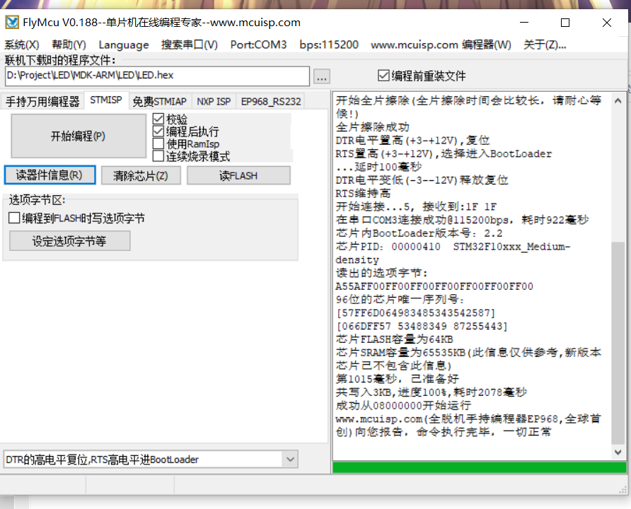
4. Results
stm32 interrupt
2, Serial port interrupt
Redo the serial communication operation of last week by serial port interrupt
1.cubeMX create project
The chip still selects 103c8
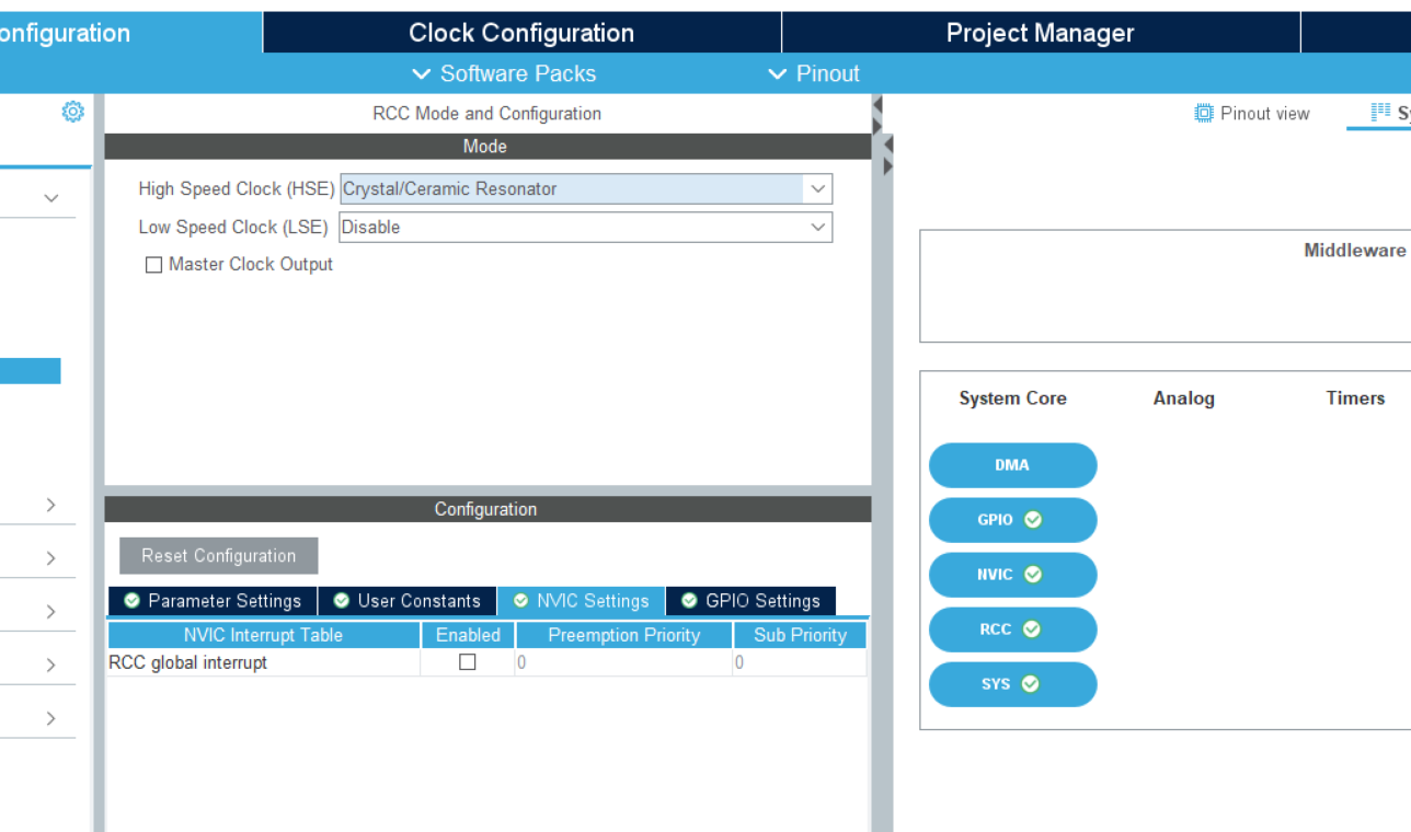
Set rcc

sys still selects serial write
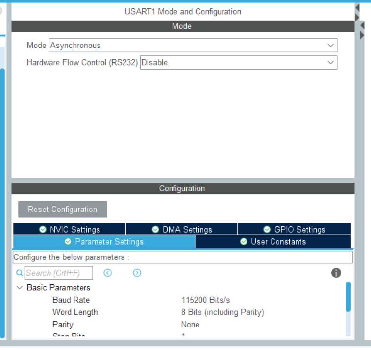
Configure serial port
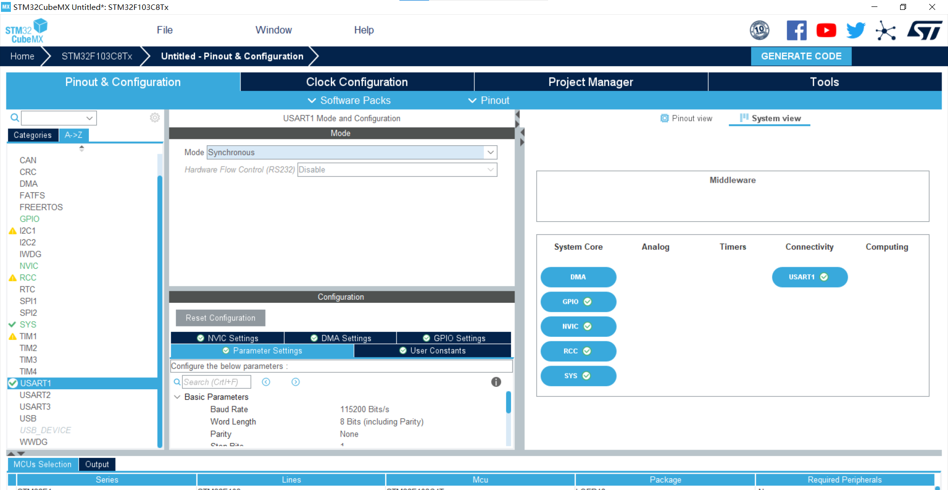
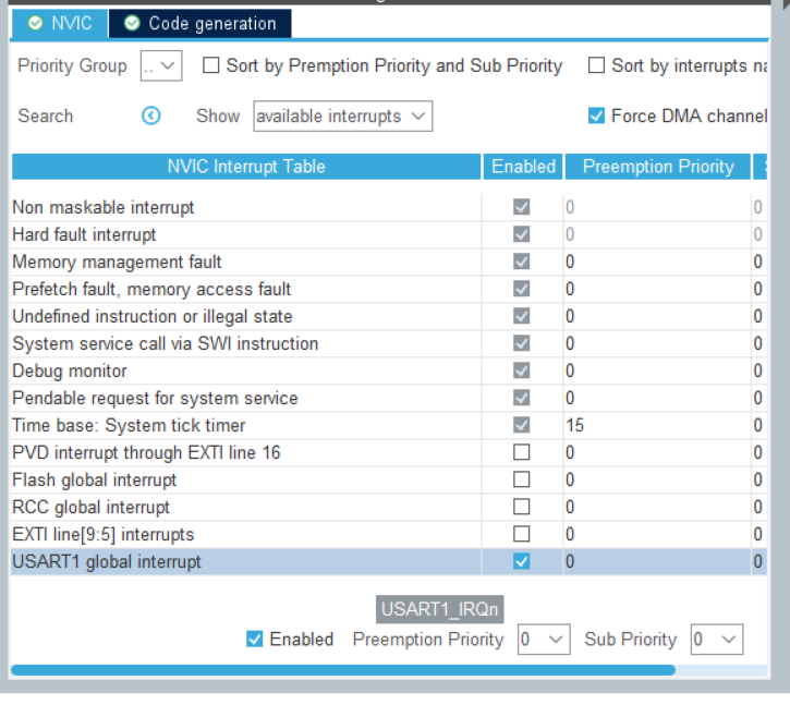
Set nvic and check the option of usart
Create project
2. Code modification
Override interrupt handler function
void HAL_UART_RxCpltCallback(UART_HandleTypeDef *huart)
{
	if(c=='0'){
		flag=0;
		HAL_UART_Transmit(&huart1, (uint8_t *)&tips2, strlen(tips2),0xFFFF);
	}
	else if(c=='1'){
		flag=1;
		HAL_UART_Transmit(&huart1, (uint8_t *)&tips1, strlen(tips1),0xFFFF);
	}
	else {
		flag=0;
		HAL_UART_Transmit(&huart1, (uint8_t *)&tips, strlen(tips),0xFFFF);
	}
		HAL_UART_Receive_IT(&huart1, (uint8_t *)&c, 1);
}
Modify the while loop in the main function
if(flag==1){
			HAL_UART_Transmit(&huart1, (uint8_t *)&message, strlen(message),0xFFFF);
			HAL_Delay(1000);
		}
Set the receive interrupt in the main function
HAL_UART_Receive_IT(&huart1, (uint8_t *)&c, 1);
Define global variables
char c;//Directive 0: stop 1: start
char message[]="hello!\n";//Output information
char tips1[]="Start.....\n";//Tip 1
char tips2[]="Stop......\n";//Tip 2
int flag=0;//Flag 0: stop sending 1. Start sending
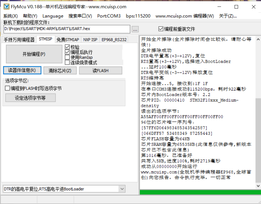
3. Burning
Compile and generate hex files and burn them
4. Results
Serial port interrupt communication
3, DMA mode
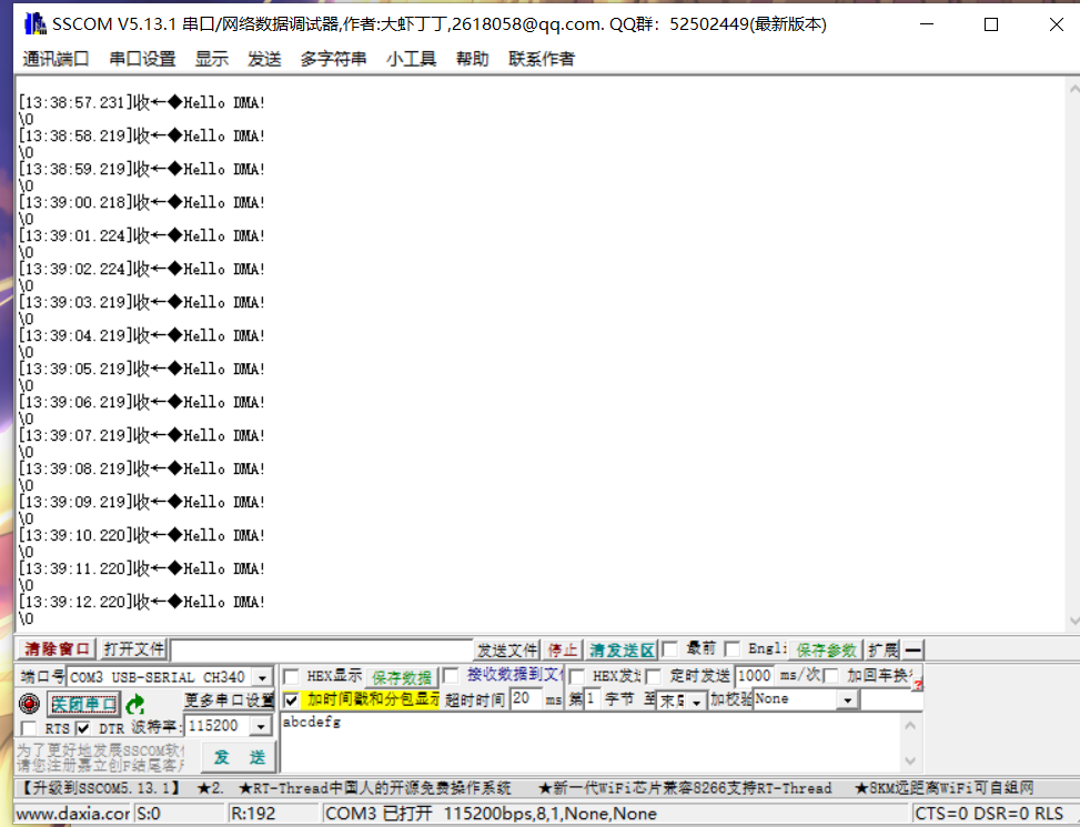
STM32 adopts serial port DMA mode and continuously sends data to the upper computer at a rate of 115200bps or higher
1.cubeMX create project
Set rcc
Set serial port
Click dma settings
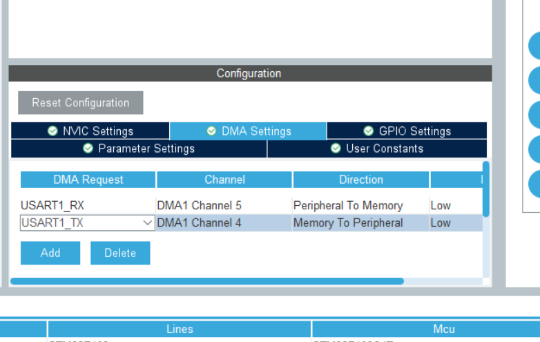
Add rxtx two channels
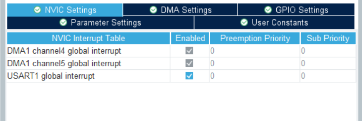
Click nvic to set enable serial port
Create project
2. Code modification
Modify main function
int main(void)
{
  HAL_Init();
  uint8_t message[] = "Hello DMA!\n";
  SystemClock_Config();
  MX_GPIO_Init();
  MX_DMA_Init();
  MX_USART1_UART_Init();
  while (1)
  {
    HAL_UART_Transmit_DMA(&huart1, (uint8_t *)message, sizeof(message));
	  HAL_Delay(1000);
  }
}
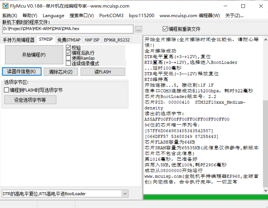
3. Burning
Compile the project and burn it
4. Results
4, Summary
The full name of DMA is Direct Memory Access, that is, Direct Memory Access. The DMA transmission mode does not require the CPU to directly control the transmission, nor does it have the process of retaining and restoring the site like the interrupt processing mode. By opening up a direct data transmission path for RAM and I/O equipment through hardware, the efficiency of the CPU can be greatly improved. STM32F1 has 12 independent configurable channels (request): DMA1 has 7 channels and DMA2 has 5 channels
Each channel is directly connected to a dedicated hardware DMA request, and each channel also supports software triggering. It can be configured by software. On the same DMA module, the priority between multiple requests can be set by software programming (there are four levels: very high, high, medium and low). When the priority settings are equal, they are determined by hardware (request 0 is better than request 1, and so on). The transmission width (byte, half word, full word) of independent data source and target data area, simulating the process of packaging and unpacking. The source and destination addresses must be aligned by data transfer width. Support circular buffer management. Each channel has three event flags (DMA half transfer, DMA transfer completion and DMA transfer error). These three event flags may logically become a separate interrupt request. The transmission between memory and memory, peripheral and memory, transmission between memory and peripheral, flash memory, SRAM, SRAM of peripheral, APB1, APB2 and AHB peripheral can be used as the source and target of access. Number of programmable data transfers: 65535 max
5, Reference
1.DMA basic principle and implementation process of STM32
2.stm32hal library serial port DMA transceiver
3.[STM32] HAL library STM32CubeMX tutorial Xi - DMA (serial port DMA sending and receiving)