GPS signal
At present, the GPS signal has three frequency points L1/L2/L3.
The traditional GPS signal is L1C/A, L1P and L2P dual band,
L1C/A and L1P are orthogonal, and L2 has only L2P without civil signal
L1C/L2C/L5C are new signals after GPS Modernization, and L1M/L2M are new military signals. The follow-up development of GPS is that these new signals gradually replace the original old signals, but this process will be quite long.

Later, we introduce the composition of the most typical L1C/A signal.
Composition of L1C/A signal
L1C/A signal consists of three parts.
1. Carrier
2. Pseudo random code, here called C/A code
3. Message, data code

The carrier is the carrier signal with L1 frequency of 1575.42MHz, which modulates the pseudo code and data to the carrier and transmits them.
C/A code is a pseudo-random sequence with a length of 1023 chips. Its design has good autocorrelation and cross-correlation characteristics, that is, the amplitude of autocorrelation function is much higher than that of cross-correlation function. This feature is used to identify different pseudo-random sequences. C/A code naturally has this good characteristic. Therefore, different satellites can be distinguished by different C/A codes.
Message and data code, including seconds in the week, ephemeris, almanac and other contents, are used for positioning solution.
Generation of C/A code signal
The generation of C/A code is the first step of receiving and processing. First, we need to describe it by program according to its definition
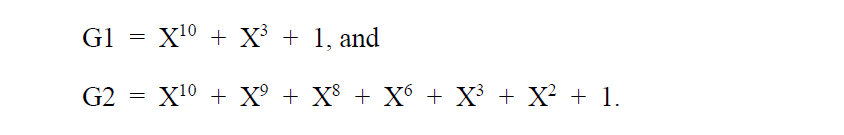
According to the GPS ICD description, the CA code transmitting generator is composed of two M sequences, which are called G1 sequence and G2 sequence respectively. The only C/A code sequence used for each satellite ranging code signal is generated by combining the G1 sequence and the G2 sequence modulo-2 sum (modulo-2 sum, in fact, is the XOR operation (^, xor()), which is binary addition).
If each M-sequence register is 10Bit, the period of G1 sequence and G2 sequence is 2 ^ 10-1 = 1023 according to the nature of M-sequence. The Gold code period obtained by the sum of two sequence modules 2 is also 1023, that is, 1023 chips (CA chips) everywhere in the book.
Since the Gold code cycle is 1023 chips, under the 1.023MHz clock drive, the length of a cycle signal (1023 chips) is 1ms, that is, all 1023 chips of a cycle are generated every 1ms, and the duration length of each chip is 1ms/1023 ≈ 1us
As shown in the figure below, there are two linear shift register groups, each of which is 10bit. The upper part generates G1 sequence and the lower part generates G2 sequence, which is controlled by GPS clock. The CA code clock is 1.023MHz.
The output C/A code is the last level register content of G1 and G2 tap selection register output for module 2 and operation output.

The use of M-sequence generally provides a polynomial through tap control;
The initial phases of G1 and G2 are set to all 1. According to the description of the tap corresponding to PRN in GPS ICD, the following matlab program can be obtained to generate 1-32 groups of C/A codes

function [caCode] = prn_GPS_L1CA_Gen(prn);

%10 Order shift register G1 and G2
%G1,G2 Register initialization
regG1 = 1 * ones(1,10);
regG2 = 1 * ones(1,10);

%Acquire satellite PRN number
snum = prn;

%determine CA Tap selection of code
switch snum
     case 1             %1 Number star
        m = 2; n = 6;
     case 2             %2 Number star
        m = 3; n = 7;
     case 3             %3 Number star
        m = 4; n = 8;
     case 4             %4 Number star
        m = 5; n = 9;
     case 5             %5 Number star
        m = 1; n = 9;
     case 6
        m = 2; n = 10;
     case 7
        m = 1; n = 8;
     case 8
        m = 2; n = 9;
     case 9
        m = 3; n = 10;
     case 10
        m = 2; n = 3;
     case 11
        m = 3; n = 4;
     case 12
        m = 5; n = 6;
     case 13
        m = 6; n = 7;
     case 14
        m = 7; n = 8;
     case 15
        m = 8; n = 9;
     case 16
        m = 9; n = 10;
     case 17
        m = 1; n = 4;
     case 18
        m = 2; n = 5;
     case 19
        m = 3; n = 6;
     case 20
        m = 4; n = 7;
     case 21
        m = 5; n = 8;
     case 22
        m = 6; n = 9;
     case 23
        m = 1; n = 3;
     case 24
        m = 4; n = 6;
     case 25
        m = 5; n = 7;
     case 26
        m = 6; n = 8;
     case 27
        m = 7; n = 9;
     case 28
        m = 8; n = 10;
     case 29
        m = 1; n = 6;
     case 30            %30 Number star
        m = 2; n = 7;
     case 31            %31 Number star
        m = 3; n = 8;
     case 32            %32 Number star
        m = 4; n = 9;
end


%reg1 Storage shift register regG1 1023 point output of
for i= 1:1023
    reg1(i) = regG1(10);                %G1 Store output to reg1
    temp = xor(regG1(3),regG1(10));     %shift register G1 Feedback from
    regG1(1,2:10) = regG1(1,1:9);       %G1 displacement
    regG1(1) = temp;                    %feedback
end

%reg2 Storage shift register regG2 1023 point output of
for i= 1:1023
    reg2(i) = xor(regG2(m),regG2(n));                %G2 Store output to reg2
    temp1 = xor(xor(regG2(2),regG2(3)), regG2(6));   %shift register G2 Feedback from
    temp2 = xor(xor(regG2(8),regG2(9)), regG2(10));
    temp = xor(temp1,temp2);
    regG2(1,2:10) = regG2(1,1:9);                    %G2 displacement
    regG2(1) = temp;                    %feedback
end


caCode = mod(reg1 + reg2 , 2);

I = find(caCode == 0);
caCode(I) = -1;
Above, we have completed the generation of GPS C/A code and stepped out of the first step of GPS signal processing.