catalogue
1, Requirements for network environment of k8s cluster
2, k8s cluster network communication flow chart
3, Analysis of communication flow of k8s cluster network
1. How to satisfy cluster Pod IP uniqueness
2. The pause container creates a shared namespace
4. The data packet is sent by our party through vxlan tunnel
5. The other party of the packet received the unpacking
6. Talk about the role of the whole process
7. Using host GW mode to improve cluster network performance
There are many principle articles. Here, we mainly use our own understanding to sort out the cluster cross host communication, which is a summary. It is recommended to read more principle introductions, and then look at the conclusion, which is suddenly enlightened.
First confirm
1, Requirements for network environment of k8s cluster
1. CNI requires that each Pod in the cluster must be assigned a unique Pod IP
2. k8s the communication in the cluster is not vxlan point-to-point communication, because all nodes in the cluster need to be interconnected
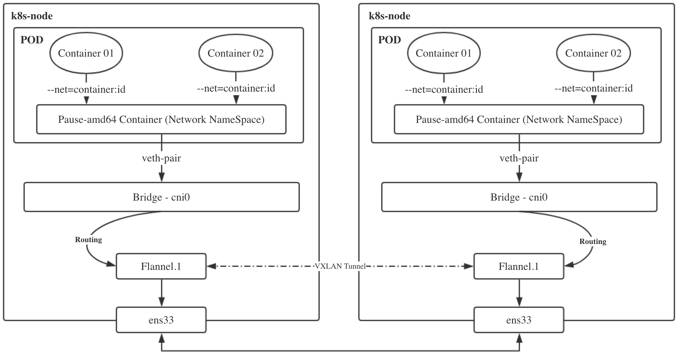
2, k8s cluster network communication flow chart
Next, we will describe the implementation process of cluster network requirements in detail according to the picture:
3, Analysis of communication flow of k8s cluster network
1. How to satisfy cluster Pod IP uniqueness
Since the POD address is required to be unique, how does flannel assign a unique address segment to each node:
When deploying a flannel, you need to specify a network segment. This environment is 10.244.0.0, and then each node deploying a flannel will be assigned a sub network segment. As shown in the figure, the pod address of the master node is always 10.244.0.x, the pod address of the node1 node is always 10.244.1.x, and the pod address of the node2 node is always 10.244.2.x, so there will be no duplication;
When communicating between nodes, use route -n to view the routing rules. The internal container communication of the master can be directly routed through cni0. When the master accesses node1, it can be routed through flannel.1
[root@k8s-master ~]# kubectl -n kube-system exec kube-flannel-ds-pbqj4 cat /etc/kube-flannel/net-conf.json
{
  "Network": "10.244.0.0/16",
  "Backend": {
    "Type": "vxlan"
  }
}
[root@k8s-master ~]# route -n Kernel IP routing table Destination Gateway Genmask Flags Metric Ref Use Iface 10.224.0.0 0.0.0.0 255.255.255.0 U 0 0 0 cni0 10.224.1.0 10.224.1.0 255.255.255.0 UG 0 0 0 flannel.1 10.224.2.0 10.224.2.0 255.255.255.0 UG 0 0 0 flannel.1 172.17.0.0 0.0.0.0 255.255.0.0 U 0 0 0 docker0
[root@k8s-master ~]# kubectl get po -owide -A
NAMESPACE     NAME                                 READY   STATUS    RESTARTS   AGE   IP              NODE         NOMINATED NODE   READINESS GATES
default       busybox-5d7b4b65d6-mk6c6             1/1     Running   0          16m   10.224.1.2      k8s-node1    <none>           <none>
kube-system   coredns-5644d7b6d9-7gw6t             1/1     Running   5          9d    10.224.0.11     k8s-master   <none>           <none>
kube-system   coredns-5644d7b6d9-vd5vk             1/1     Running   5          9d    10.224.0.10     k8s-master   <none>           <none>
[root@k8s-master ~]# cat /run/flannel/subnet.env
FLANNEL_NETWORK=10.244.0.0/16
FLANNEL_SUBNET=10.224.0.1/24
FLANNEL_MTU=1450
FLANNEL_IPMASQ=true
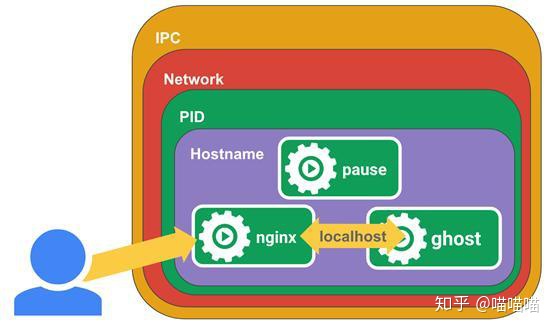
2. The pause container creates a shared namespace
Each pod in the k8s cluster corresponds to the shared namespace created by the pause container to realize container interworking. Therefore, it can be seen from the figure that when the so-called cluster cross host communication object is pod, the internal container has realized interworking, and now it only needs to communicate with the external interface uniformly. Find a picture to understand.
3. pod network plug-in bridge
What is a virtual bridge? It is used to collect container networks and distribute them uniformly. The purpose is to provide a unified scheduling for container communication. The bridge here refers to cni0. Cni0 is essentially the same as docker0. All container communications must pass through cni0, and cni0 can be used directly to judge internal communication. After all, pod is on the same bridge. Please stay here, Cross host, continue to the next step.
[root@k8s-master ~]# brctl show
bridge name	bridge id		STP enabled	interfaces
cni0		8000.86355d489a2a	no		veth523f7aca
							            veth8e5df844
                                        veth6e1df844
                                        veth9e4df844
docker0		8000.02426bf09add	no
4. The data packet is sent by our party through vxlan tunnel
The full name of VXLAN is Virtual eXtensible Local Area Network, which is mainly used to build a virtual two-layer network through a three-layer network. VXLAN is essentially a tunnel technology to establish a logical tunnel on the IP network between the source network equipment and the destination network equipment, The user side message is forwarded through this tunnel after specific encapsulation. From the user's point of view, the server accessing the network is like connecting to different ports of a virtual layer-2 switch.
VTEP (VXLAN Tunnel Endpoints) is the edge device of VXLAN network and the starting and ending point of VXLAN tunnel. VXLAN encapsulates and de encapsulates the user's original data frame on VTEP. In K8s, the corresponding is flannel.1
VNI (VXLAN Network Identifier): VNI is the identifier of each vxlan. Generally, each VNI corresponds to a tenant. The. 1 of flannel.1 is the so-called identifier
What do you mean? If a family arrives at cni0, they can communicate with each other. During cross host communication, the cni0 bridge determines the target through routing information. At present, the two nodes only have three layers of interworking, that is, IP address interworking. vxlan tunnel sends network requests to vtep. Vtep records the addresses of a and B, mac and other information, and uses the ens33 network card after packets, A sends the packet to B's ens33 network card.
5. The other party of the packet received the unpacking
After receiving the sent packet, B arrives at the B.flannel.1 site. Once your identifier is 1, I am also 1. Yes, start unpacking. When the packet is unpacked, I can see A's address and other information. I don't know it. Give it to the route, and then go to B's Bridge to finally realize communication. vice versa. As for the role of flannel in this process, vxlan defaults to point-to-point mode. The k8s cluster comes with an etcd cluster. Flannel is deployed on the node to collect address mac and other information to report, so as to realize the distributed registry. This is also the reason why flannel. 1 acts as vtep.
6. Talk about the role of the whole process
pause container: create a virtual cyberspace to find a home for the container in the same pod
cni0: the role of bridge, the entrance and exit of container traffic, and the commander of container communication
flannel.1: vtep role, solve vxlan single point problem, unpack and match with. 1 identifier
ens33: the actual interface of network communication, the two tier is not powerful, it can only be suck up and go from here.
Flannel: node agent, record the host information, report it to etcd, maintain flannel.1, and ensure that it is known when unpacking
vxlan: virtual tunnel technology, the commander who steals the day, realizes virtual layer-2 communication, that is, vtep direct communication between the two sides
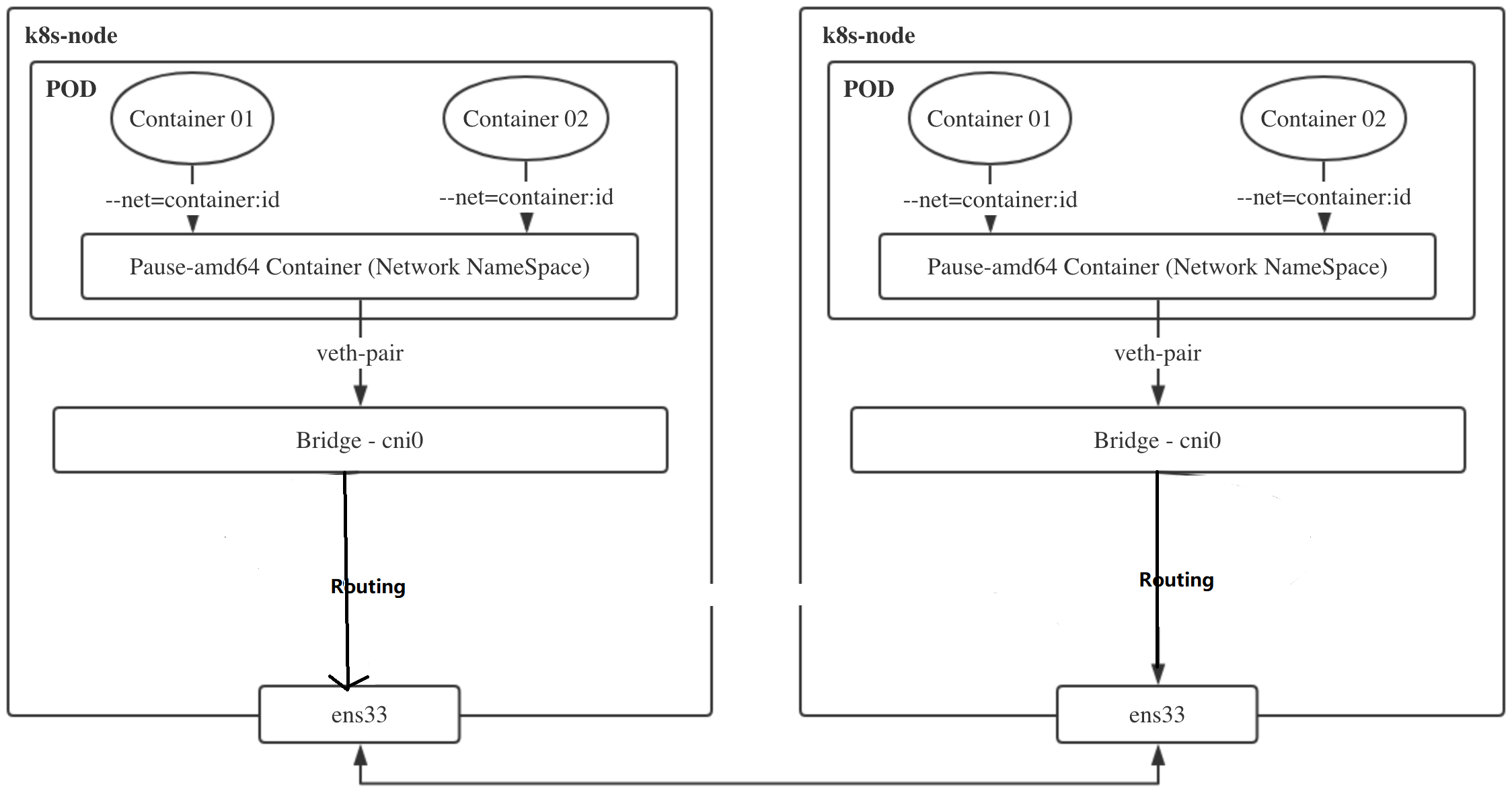
7. Using host GW mode to improve cluster network performance
vxlan mode is applicable to the three-tier reachable network environment and has loose requirements for the cluster network. However, at the same time, it will carry out additional packet and unpacking through VTEP equipment, which will bring additional overhead to the performance.
The purpose of host GW is to send the traffic of the local cni0 bridge to the cni0 bridge of the destination host. In fact, many clusters are deployed in the same layer-2 network environment, and the layer-2 host can be directly used as the traffic forwarding gateway. In this way, the traffic can be forwarded directly through the routing table without unpacking.
What do you mean, you don't need to unpack layer 2 - layer 3 - layer 3 of the other party - layer 2 of the other party. Once you see that you can communicate directly, you can directly communicate with layer 2 cni0. How can you judge whether I can reach layer 2 or layer 3?
1. The second layer means that the interfaces at both ends are in the bridge mode and interconnected through access or trunk.
2. The third layer is that the interface modes at both ends are in the route routing mode, and the IP address interconnection is directly configured on the interface.
Generally speaking, the second layer checks MAC forwarding on the same network segment, and the third layer checks routing forwarding across network segments. If the same network segment, use the host GW mode decisively!
Why does the three-tier reachable network not directly use the gateway to forward traffic?
According to the routing rules in the kernel, the gateway must be in the same network segment as at least one IP in the host.
Because k8s all nodes in the cluster need to realize Pod interworking, it means that the host GW mode requires the entire cluster nodes to be in the same layer 2 network.
Modify the network backend of flannel:
$ kubectl edit cm kube-flannel-cfg -n kube-system
...
net-conf.json: |
    {
      "Network": "10.244.0.0/16",
      "Backend": {
        "Type": "host-gw"
      }
    }
kind: ConfigMap
...
reconstruction Flannel of Pod $ kubectl -n kube-system delete po kube-flannel-ds-amd64-5dgb8 kube-flannel-ds-amd64-c2gdc kube-flannel-ds-amd64-t2jdd
# After the Pod is newly started, check the log and the word backend type: host GW appears $ kubectl -n kube-system logs -f kube-flannel-ds-amd64-4hjdw I0704 01:18:11.916374 1 kube.go:126] Waiting 10m0s for node controller to sync I0704 01:18:11.916579 1 kube.go:309] Starting kube subnet manager I0704 01:18:12.917339 1 kube.go:133] Node controller sync successful I0704 01:18:12.917848 1 main.go:247] Installing signal handlers I0704 01:18:12.918569 1 main.go:386] Found network config - Backend type: host-gw I0704 01:18:13.017841 1 main.go:317] Wrote subnet file to /run/flannel/subnet.env
View node routing table:

$ route -n
Destination     Gateway         Genmask         Flags Metric Ref    Use Iface
10.244.0.0      0.0.0.0         255.255.255.0   U     0      0        0 cni0
172.17.0.0      0.0.0.0         255.255.0.0     U     0      0        0 docker0