empirical conclusion
1. Experimental task 1
task1.asm
 1 assume cs:code, ds:data
 2
 3 data segment
 4     x db 1, 9, 3
 5     len1 equ $ - x
 6
 7     y dw 1, 9, 3
 8     len2 equ $ - y
 9 data ends
10
11 code segment
12 start:
13     mov ax, data
14     mov ds, ax
15
16     mov si, offset x
17     mov cx, len1
18     mov ah, 2
19  s1:mov dl, [si]
20     or dl, 30h
21     int 21h
22
23     mov dl, ' '
24     int 21h
25
26     inc si
27     loop s1
28
29     mov ah, 2
30     mov dl, 0ah
31     int 21h
32
33     mov si, offset y
34     mov cx, len2/2
35     mov ah, 2
36  s2:mov dx, [si]
37     or dl, 30h
38     int 21h
39
40     mov dl, ' '
41     int 21h
42
43     add si, 2
44     loop s2
45
46     mov ah, 4ch
47     int 21h
48 code ends
49 end start
function:

Answer question ①
① line27, when the assembly instruction loop s1 jumps, it jumps according to the displacement. Check the machine through debug disassembly
What is the jump displacement of the code? (the displacement value is answered in decimal) from the perspective of CPU, it is explained
How to calculate the offset address of the instruction after the jump label s1.
Disassembly
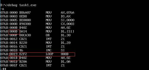
loop At s1, it jumps from 001B to 000D, and the displacement is - 14 (F2) bytes. At this time, the program has not run, so the displacement is calculated by 8086 CPU according to loop during assembly The calculated position and s1 size jump forward, so the displacement is negative, which is represented by complement in the machine code.
Answer question ②
② line44. When the assembly instruction loop s2 jumps, it jumps according to the displacement. Check the machine through debug disassembly
Code, analyze the jump displacement? (the displacement value is answered in decimal) from the perspective of CPU
How to calculate the offset address of the instruction after the jump label s2.
Disassembly
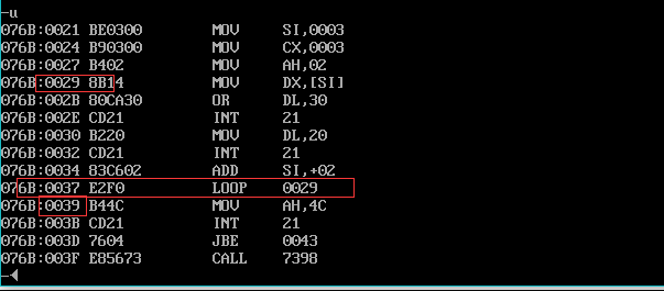
loop s2, from 0039 to 0029, the displacement is - 16 (F0) bytes. At this time, the program does not run, and the offset address is calculated during assembly.
2. Experimental task 2
task2.asm
 1 assume cs:code, ds:data
 2
 3 data segment
 4     dw 200h, 0h, 230h, 0h
 5 data ends
 6
 7 stack segment
 8     db 16 dup(0)
 9 stack ends
10
11 code segment
12 start:
13     mov ax, data
14     mov ds, ax
15
16     mov word ptr ds:[0], offset s1
17     mov word ptr ds:[2], offset s2
18     mov ds:[4], cs
19
20     mov ax, stack
21     mov ss, ax
22     mov sp, 16
23
24     call word ptr ds:[0]
25 s1: pop ax
26
27     call dword ptr ds:[2]
28 s2: pop bx
29     pop cx
30
31     mov ah, 4ch
32     int 21h
33 code ends
34 end start
Disassembly:
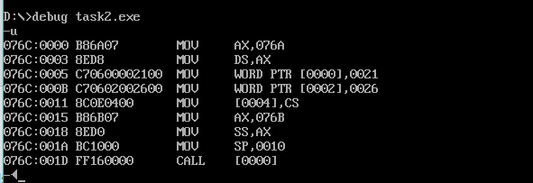
It can be seen that s1:0021, s2:0026 and CS: 076c are saved in DS: [0], DS [2] and DS [4] respectively.
According to the principle of call instruction, before the program executes to exit (line31), register ax should store ds:[0], register cx should store ds:[4], and register bx should store ds: [2],
Register (ax) =0021 Register (bx) = 0026 register (cx) = 076C
Results before program execution and exit:
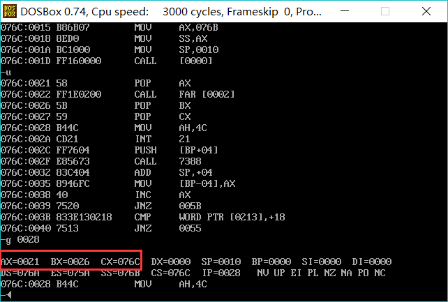
The results are consistent with the theoretical analysis.
3. Experimental task 3
Write the 8086 assembly source program task3.asm to output this group of continuous data in the data section in decimal form on the screen, and the data is separated by spaces.
The data in the data section is as follows:
data segment
  x db 99, 72, 85, 63, 89, 97, 55
  len equ $- x
data ends
requirement:
Write subroutine printNumber
Function: output a two digit number in decimal form
Entry parameter: register ax (data to be output -- > ax)
Outlet parameters: None
Write the subroutine printSpace
Function: print a space
Entry parameters: None
Outlet parameters: None
In the main code, the addressing mode and loop are comprehensively applied, and printNumber and printSpace are called to realize the subject requirements.
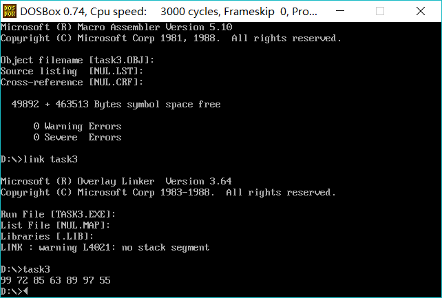
task3.asm code
 1 assume cs:code, ds:data
 2 data segment
 3   x db 99, 72, 85, 63, 89, 97, 55
 4   len equ $- x
 5 data ends
 6 code segment
 7 start:
 8 mov ax,data
 9 mov ds,ax
10 mov si,0
11 mov cx,7
12 s: mov ax,0
13 mov al,ds:[si]
14 call s1
15 call s2
16 add si,1
17 loop s
18 mov ah, 4ch
19 int 21h
20
21 s1: mov bl,10
22 div bl
23 mov di,16
24 mov ds:[di],al;******shiwei
25 mov ds:[di+1],ah;****gwei
26 mov dl,ds:[di]
27 add dl,30h
28 mov ah,2
29 int 21h
30 mov dl,ds:[di+1]
31 add dl,30h
32 int 21h
33 ret
34
35 s2: mov dl," "
36 mov ah,2
37 int 21h
38 ret
39
40 code ends
41 end start
function:
4. Experimental task 4
For 8086 CPU, the known logical segment is defined as follows:
data segment
str db 'try'
len equ $ - str
data ends
Write 8086 assembly source program task4.asm, specify the color and line on the screen, and output the string on the screen.
requirement:
Write subroutine printStr
Function: display the string on the screen in the specified line and in the specified color
Entry parameters
The address of the first character of the string -- > ds: Si (where, the segment address of the segment where the string is located -- > DS, the offset of the starting address of the string)
Move address - > SI)
String length -- > CX
String color -- > bl
Specified line -- > BH (value: 0 ~ 24)
Outlet parameters: None
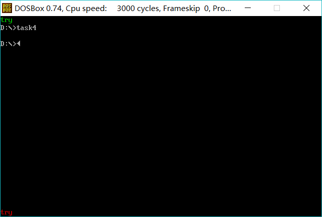
task4.asm Code:
 1 assume cs:code, ds:data
 2 data segment
 3 str db 'try'
 4 len equ $ - str
 5 data ends
 6 code segment
 7 start:
 8 mov ax,data
 9 mov ds,ax
10 mov si,0
11 mov cx,3
12 mov bl,2;green
13 mov bh,0
14 call s1
15 mov si,0
16 mov cx,3
17 mov bl,4;gules
18 mov bh,24
19 call s1
20 mov ah,4ch
21 int 21h
22
23 s1:mov ax,0b800h
24 mov es,ax
25 mov al,bh
26 push bx
27 mov bl,160
28 mul bl
29 pop bx
30 s: mov dl,ds:[si]
31 mov dh,bl
32 mov di,ax
33 mov es:[di],dx
34 add ax,2
35 add si,1
36 loop s
37 ret
38 code ends
39 end start
function:
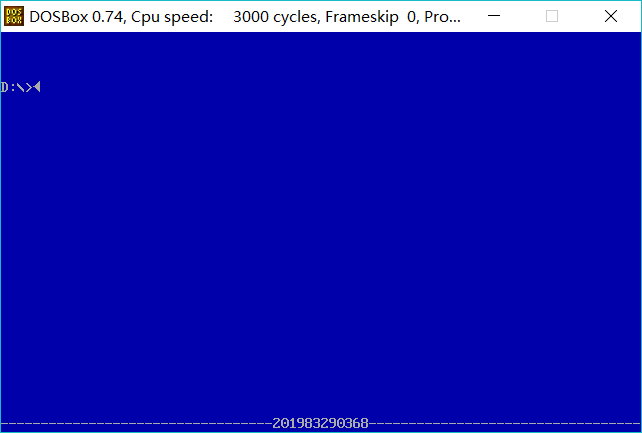
5. Experimental task 5
At 80 × In 25 color character mode, the student number is displayed in the middle of the last line of the screen. It is required that the student number and broken lines on both sides of the output window are displayed in white foreground.
 1 assume cs:code, ds:data
 2 data segment
 3 stu_no db '201983290368'
 4 len = $ - stu_no
 5 data ends
 6 code segment
 7 start:
 8 mov ax,data
 9 mov ds,ax
10 mov ax,0b800h
11 mov es,ax
12 mov bl," "
13 mov bh,23
14 mov di,0
15 mov cx,780h
16 s:mov es:[di],bx
17 add di,2
18 loop s
19
20 mov cx,34
21 s1:mov bl,"-"
22 mov es:[di],bx
23 add di,2
24 loop s1
25
26 mov si,0
27 mov cx,12
28 s2:mov bl,ds:[si]
29 mov es:[di],bx
30 add di,2
31 add si,1
32 loop s2
33 mov cx,34
34 s3:mov bl,"-"
35 mov es:[di],bx
36 add di,2
37 loop s3
38 mov ah,4ch
39 int 21h
40
41 code ends
42 end start
function:
Experimental summary
The stack can solve the register conflict problem of subroutines. For some registers with special uses, such as cx, ax, etc., put the register on the stack before using the register in the subroutine, wait for it to return to the corresponding register after using it.