Experimental task 1
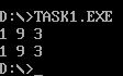
Program task1.asm source code, and running screenshot
assume cs:code, ds:data

data segment
    x db 1, 9, 3
    len1 equ $ - x

    y dw 1, 9, 3
    len2 equ $ - y
data ends

code segment
start:
    mov ax, data
    mov ds, ax

    mov si, offset x
    mov cx, len1
    mov ah, 2
 s1:mov dl, [si]
    or dl, 30h
    int 21h

    mov dl, ' '
    int 21h

    inc si
    loop s1

    mov ah, 2
    mov dl, 0ah
    int 21h

    mov si, offset y
    mov cx, len2/2
    mov ah, 2
 s2:mov dx, [si]
    or dl, 30h
    int 21h

    mov dl, ' '
    int 21h

    add si, 2
    loop s2

    mov ah, 4ch
    int 21h
code ends
end start
Q1 line27, when the assembly instruction loop s1 jumps, it jumps according to the displacement. Check the machine code through debug disassembly and analyze the jump displacement? (the displacement value is answered in decimal) from the perspective of the CPU, explain how to calculate the offset address of the instruction after the jump label s1.
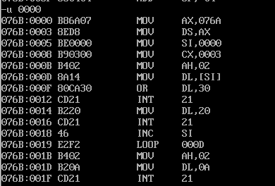
The displacement is 14. 001B-000D=000E=14.
The transfer instruction machine code is E2F2. F2=(11110010) complement = (10001110) original = - 14. After the CPU executes the transfer instruction, IP first + 2 and then minus 14.
Q2 line44. When the assembly instruction loop s2 jumps, it jumps according to the displacement. Check the machine code through debug disassembly and analyze the jump displacement? (the displacement value is answered in decimal) from the perspective of the CPU, explain how to calculate the offset address of the instruction after the jump label s2.
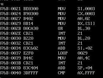
The displacement is 16. 0039-0029=0010=16
The transfer instruction machine code is E2F0. F2=(11110000) complement = (10010000) original = - 16. After the CPU executes the transfer instruction, IP first + 2 and then subtract 16.
Experimental task 2
Program task2.asm source code
assume cs:code, ds:data

data segment
    dw 200h, 0h, 230h, 0h
data ends

stack segment
    db 16 dup(0)
stack ends

code segment
start:
    mov ax, data
    mov ds, ax

    mov word ptr ds:[0], offset s1
    mov word ptr ds:[2], offset s2
    mov ds:[4], cs

    mov ax, stack
    mov ss, ax
    mov sp, 16

    call word ptr ds:[0]
s1: pop ax

    call dword ptr ds:[2]
s2: pop bx
    pop cx

    mov ah, 4ch
    int 21h
code ends
end start
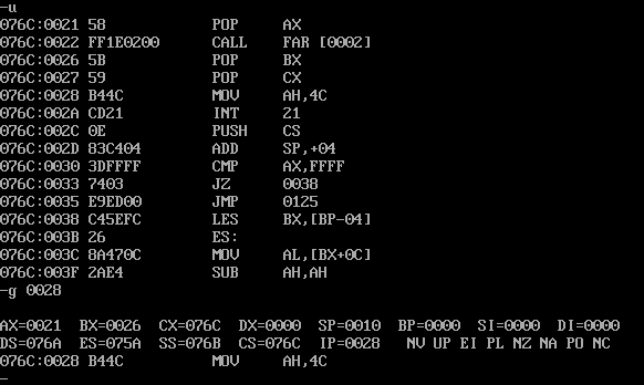
Q1 according to the jump principle of call instruction, it is analyzed theoretically that before the program executes to exit (line31), register (ax) = 0021 register (bx) = 0026 register (cx) = 076C
call first press ip or cs:ip on the stack, and then jump.
ax is the segment address of s1. cx:bx is the offset address of s2.
Q2 assemble and link the source program to get the executable program task2.exe. Use debug to observe and verify whether the debugging results are consistent with the theoretical analysis results.
Experimental task 3
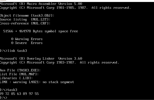
The program source code task3.asm is given
assume cs:code, ds:data
data segment
    x db 99, 72, 85, 63, 89, 97, 55
    len equ $- x
data ends
code segment
start:
    mov ax, data
    mov ds, ax
    mov cx, len
    mov byte ptr ds:[len], 10
    mov si, 0
s:
    mov al, ds:[si]
    mov ah, 0
    call printNumber
    call printSpace
    inc si
    loop s

    mov ah, 4ch
    int 21h

printNumber:
    div byte ptr ds:[len]
    ;AH:AL more than:Number quotient

    mov bx, ax

    mov dl, bl
    add dl, 30h
    mov ah, 2
    int 21h

    mov dl, bh
    add dl, 30h
    mov ah, 2
    int 21h

    ret

printSpace:
    mov ah, 2
    mov dl, ' '
    int 21h
    ret
code ends
end start
Screenshot of running test
Experimental task 4
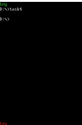
The program source code task4.asm is given
assume ds:data, cs:code

data segment
str db 'try'
len equ $ - str
data ends

code segment
start:
    mov ax,data
    mov ds,ax

    mov ax, 0b800h
    mov es, ax
    mov si, 0
    mov di, 0
    mov cx, len
    mov bl, 02h
    call printStr


    mov si, 0
    mov di, 160 * 24
    mov cx, len
    mov bl, 04h
    call printStr

    mov ax, 4c00h
    int 21h

printStr:
s:
    mov al, [si]
    mov es:[di], al
    inc di
    mov es:[di], bl
    inc di
    inc si
    loop s
    ret
code ends
end start
Screenshot of running test
Experimental task 5
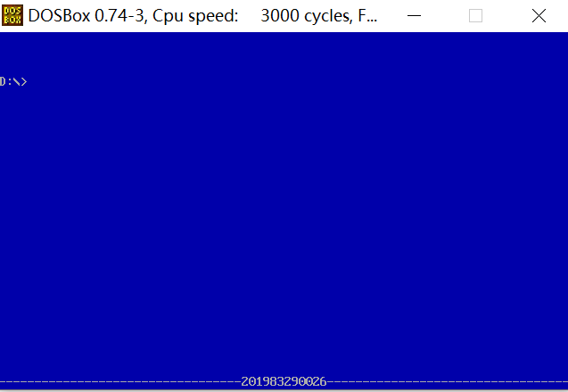
The program source code task5.asm is given
assume cs:code, ds:data

data segment
    stu_no db '201983290026'
    len = $ - stu_no
data ends

code segment
start:
    mov ax,data
    mov ds,ax

    mov ax, 0b800h
    mov es, ax
    mov di, 0
    mov bl, 17h
    mov cx, 80 * 25

    s1:
    mov al, ' '
    mov es:[di], al
    inc di
    mov es:[di], bl
    inc di
    loop s1

    mov di, 160 * 24
    mov cx, 34
s2:
    mov al, '-'
    mov es:[di], al
    inc di
    mov es:[di], bl
    inc di
    loop s2

    mov di, 160 * 24 + 34 * 2
    mov cx, 12
    mov si, 0
s3:
    mov al, [si]
    mov es:[di], al
    inc di
    mov es:[di], bl
    inc di
    inc si
    loop s3

    mov di, 160 * 24 + 46 * 2
    mov cx, 34
s4:
    mov al, '-'
    mov es:[di], al
    inc di
    mov es:[di], bl
    inc di
    loop s4

    mov ax, 4c00h
    int 21h
code ends
end start
Screenshot of running test
Experimental summary
- Starting from 0b800, there is a video memory with a size of 80x25. Each unit has two bytes. The high byte is placed in the data, and the low byte is used to set the display format.
- The same register can be used for many purposes. It can hold data of many different instructions.