4, Experimental conclusion
1. Experimental task 1
- task1.asm source code
 1 assume cs:code, ds:data
 2
 3 data segment
 4     x db 1, 9, 3
 5     len1 equ $ - x
 6
 7     y dw 1, 9, 3
 8     len2 equ $ - y
 9 data ends
10
11 code segment
12 start:
13     mov ax, data
14     mov ds, ax
15
16     mov si, offset x
17     mov cx, len1
18     mov ah, 2
19  s1:mov dl, [si]
20     or dl, 30h
21     int 21h
22
23     mov dl, ' '
24     int 21h
25
26     inc si
27     loop s1
28
29     mov ah, 2
30     mov dl, 0ah
31     int 21h
32
33     mov si, offset y
34     mov cx, len2/2
35     mov ah, 2
36  s2:mov dx, [si]
37     or dl, 30h
38     int 21h
39
40     mov dl, ' '
41     int 21h
42
43     add si, 2
44     loop s2
45
46     mov ah, 4ch
47     int 21h
48 code ends
49 end start
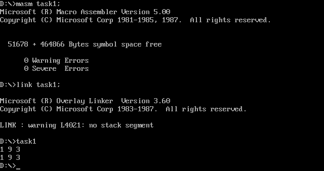
- Operation results
- Question 1
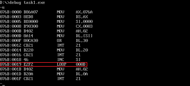
Jump displacement: according to the jump instruction E2F2, F2 is the complement, and the decimal number corresponding to the original code is - 14, so the displacement is - 14.
For the CPU, when executing the loop instruction, the current IP address is 0019. After adding the number of bytes (2 bytes) of the instruction, it is 001B. After adding the displacement - 14, the jump address is 000D, that is, the offset address of the instruction after label s1.
- Question 2
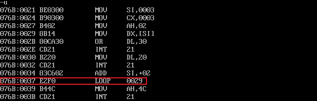
Jump displacement: according to the jump instruction E2F0, F0 is the complement, and the decimal number corresponding to the original code is - 10, so the displacement is - 10.
For the CPU, when executing the loop instruction, the current IP address is 0037. After adding the number of bytes (2 bytes) of the instruction, it is 001B. After adding the displacement of - 10, the jump address is 0029, that is, the offset address of the instruction after label s2.
- Question 3
2. Experimental task 2
- task2.asm source code
 1 assume cs:code, ds:data
 2
 3 data segment
 4     dw 200h, 0h, 230h, 0h
 5 data ends
 6
 7 stack segment
 8     db 16 dup(0)
 9 stack ends
10
11 code segment
12 start:
13     mov ax, data
14     mov ds, ax
15
16     mov word ptr ds:[0], offset s1
17     mov word ptr ds:[2], offset s2
18     mov ds:[4], cs
19
20     mov ax, stack
21     mov ss, ax
22     mov sp, 16
23
24     call word ptr ds:[0]
25 s1: pop ax
26
27     call dword ptr ds:[2]
28 s2: pop bx
29     pop cx
30
31     mov ah, 4ch
32     int 21h
33 code ends
34 end start
- Debug screenshot
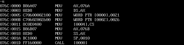
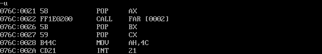
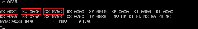
After analysis, debugging and verification, register (ax)=21H, (bx)=26H, (cx)=067C.
Among them, the call instruction will stack the instruction address in the ip register, so when it comes out of the stack, it is the address of the next instruction after the call instruction, i.e. 0021H, which is assigned to ax.
The call dword instruction will stack the code segment address in cs and the instruction address in ip respectively, so 26H and 067C are assigned to CX and BX respectively when they are out of the stack.
3. Experimental task 3
- task3.asm source code
 1 assume ds:data, cs:code
 2
 3 data segment
 4     x db 99, 72, 85, 63, 89, 97, 55
 5     len equ $- x
 6 data ends
 7
 8 code segment
 9 start:
10     mov ax,data
11     mov ds,ax
12     mov si,0
13     mov cx,len
14 s:  call printNumber
15     call printSpace
16     inc si
17     loop s
18
19     mov ax,4c00h
20     int 21h
21
22 printNumber:
23     mov ah, 0
24     mov al, [si]
25     mov bl, 10
26     div bl
27     mov bl,al
28     mov bh,ah
29
30     mov ah,2
31     mov dl,bl;Printer
32     or dl,30h
33     int 21h
34
35     mov dl,bh;Print remainder
36     or dl,30h
37     int 21h
38     ret
39
40
41     printSpace:
42     mov ah,2
43     mov dl,' '
44     int 21h
45     ret
46 code ends
47 end start
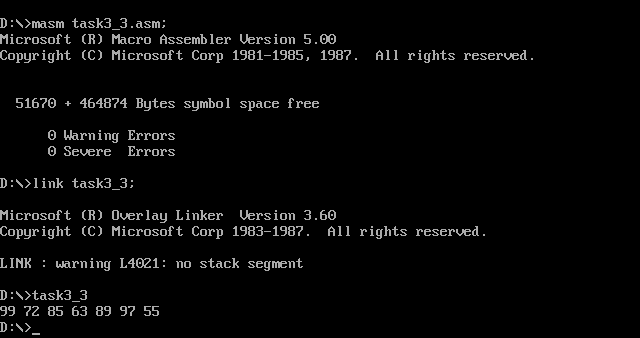
- Screenshot of running test
4. Experimental task 4
- task4.asm source code
 1 assume cs:code, ds:data
 2
 3 data segment
 4     str db 'try'
 5     len equ $ - str
 6 data ends
 7
 8 code segment
 9 start:
10     mov ax, data
11     mov ds, ax
12     mov ax,0b800H
13     mov es,ax
14
15     mov si,offset printStr
16     mov ah,2
17     mov bx,0
18     call si
19
20     mov si,offset printStr
21     mov ah,4
22     mov bx,0f00H
23     call si
24
25     mov ah, 4ch
26     int 21h
27
28 printStr:
29     mov cx,len
30     mov si,0
31 s:  mov al,[si]
32     mov es:[bx+si],ax
33     inc si
34     inc bx
35     loop s
36     ret
37
38 code ends
39 end start
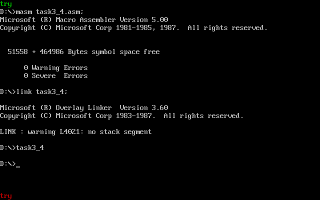
- Screenshot of running test
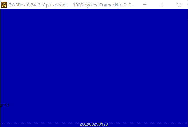
5. Experimental task 5
- task5.asm source code
 1 assume cs:code, ds:data
 2
 3 data segment
 4     stu_no db '201983290473'
 5     len = $ - stu_no
 6 data ends
 7
 8 code segment
 9 start:
10     mov ax, data
11     mov ds, ax
12     mov ax,0b800H
13     mov es,ax
14
15     mov cx,0780H
16     mov ah,10H
17     mov al,' '
18     mov bx,0
19
20 s:  mov es:[bx],ax
21     add bx,2
22     loop s
23
24     mov cx,80
25     mov ah,17H
26     mov al,'-'
27 s1: mov es:[bx],ax
28     add bx,2
29     loop s1
30
31     mov cx,len
32     mov bx,0F44H
33     mov si,0
34 s2: mov al,[si]
35     mov es:[bx],ax
36     inc si
37     add bx,2
38     loop s2
39
40     mov ah, 4ch
41     int 21h
42
43 code ends
44 end start
- Screenshot of running test
5, Experimental summary
1. This experiment is mainly to try to realize some modular programming, and understand the display memory space more thoroughly.
2. In the confirmatory experiment, it is mainly understood that the last two bits of the machine code of loop instruction are signed displacements, which are given in the form of complement.