preface
Editor of this article: Sun Shaohui, if there is infringement, please contact V18149072101
1, Article content:
Esp8266 is connected with 51 single chip microcomputer to realize wireless control of light switch and other actions
2, Realization idea
3, Implementation tutorial
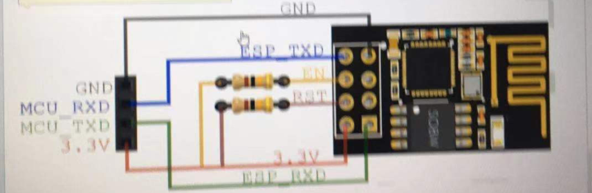
1: Connection between ESP8266 and PC serial port assistant
VCC, GND and ch of ESP8266 module_ PD, utxd and urxd ports are respectively connected to 3.3v, ground, 3.3v, RXD and TXD of USB to TTL module, and can not be connected to 5V.
2. Download the serial port assistant and connect to ESP8266
Serial port debugging assistant download link
Extraction code: 3tz5
1: Adjust the serial port assistant baud rate to 115200, which is the initial baud rate of ESP8266,
2: Open serial port
3: Input the command "AT" in the serial port and send it, and return OK, indicating that the connection is successful. If the code is garbled, check whether the baud rate is true
3. Configure esp8266 (issue configuration instruction through PC)
3.1 instruction introduction
- AT + CIOBAUD=X is the baud rate of the module to be changed, and X is the baud rate to be changed
- AT+CIOBAUD=X
AT + CWMODE=X (set working mode command, X can be 1, 2 and 3, as follows:
1: Station mode / / as a client
2: AP mode / / as hotspot
3: Station+AP mode / / mixed mode
Station can be understood as allowing the wifi module to connect to the router or hotspot. At this time, the module acts as a client
AP mode can be understood as that the module itself is a hotspot, and the mobile phone or computer can connect to this hotspot. At this time, the module acts as a server.
AP mode is used here - AT+RST (restart command. It takes effect only after a new working mode is set. Sending other commands after this command may show that the serial port is invalid. You need to exit the serial port debugging assistant and re-enter it)
- AT+CWSAP? (you can view the specific information of module hotspots in the current AP mode)
- AT+CIFSR (view IP address)
- AT+CIPMUX=1
- AT+CIPSERVER=1, X (1 means to start the server, and X is the port number set by yourself)
- AT+CWLAP / / the wireless list is displayed
- AT+CWJAP = "WIFI name", "password"
Note: 6 and 7 commands should be reconfigured after power failure
3.2 demonstration
- Send 'AT' and return to OK;
- Send 'AT+CWMODE=2' and set the mode to hot AP mode
- AT+CWSAP = "ESP8266", "0123456789", 11,3 / / create your own WIFI hotspot
- Send 'AT+RST';, Reply OK and the hotspot is established
- AT+CIPMUX=1
- At + cipserver = 16666 / / configure port number
- These two lines need to be reconfigured after power failure
- AT+CIFSR / / get IP address
Now that the hotspot has been established, you can use the mobile phone WIF to search the ESP8266 and connect it. The Android mobile terminal can download the TCP connection software,

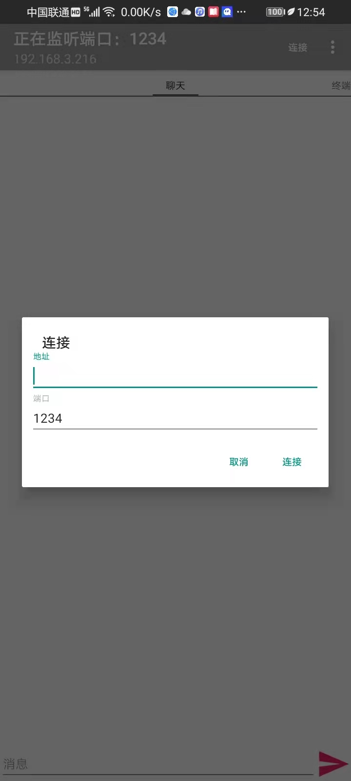
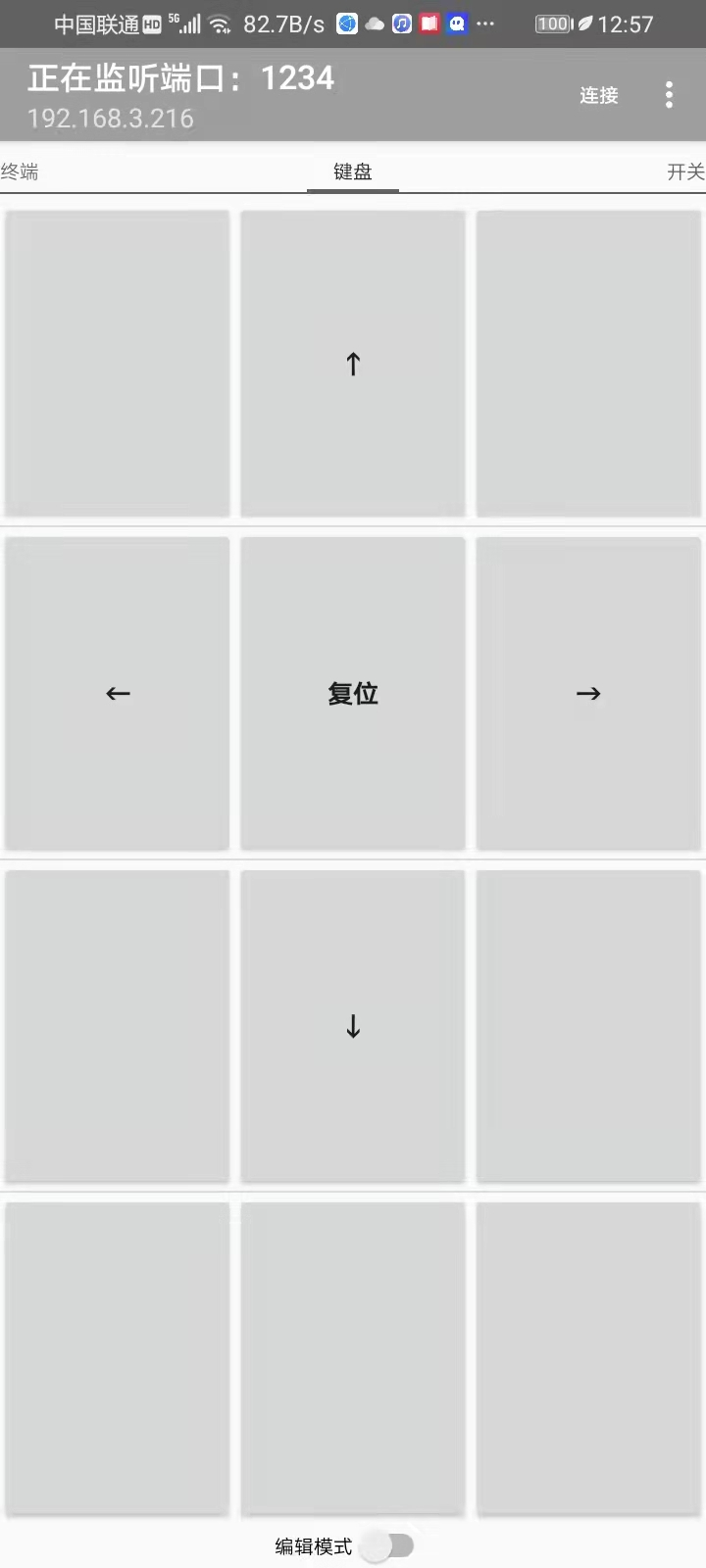
- Open the software interface
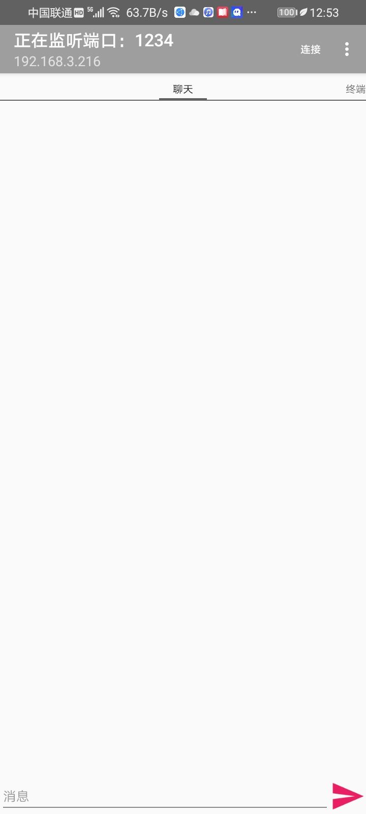
- Input the IP address just queried and the port number set by yourself to connect with the mobile phone. If my MCU is not around, I won't do a demonstration
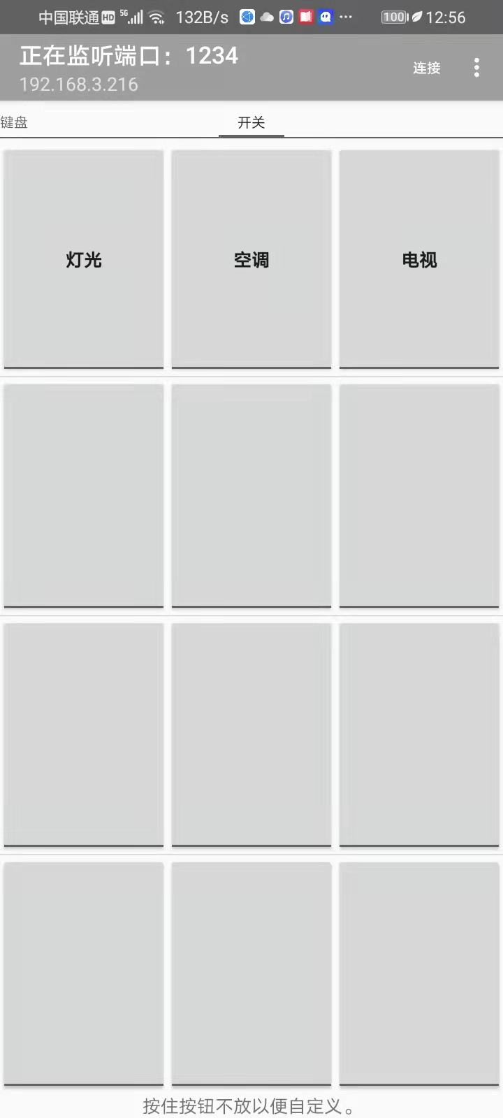
- Software interface, these things can be customized
- The baud rate of ESP8266 is set to be the same as that of 51. Because 51 uses 12M crystal oscillator, it is set to 4800 here,
- AT + CIOBAUD=X, X is the baud rate to be changed,
- Send AT+RST, restart the device,
- Then set the baud rate of PC serial port assistant to the baud rate just changed,
- Send AT. If OK is returned, the setting is completed
Don't be happy here too early. We just finished what the single chip microcomputer should do by hand. To complete the automatic connection, we must write our previous process into the 51 single chip microcomputer and let it replace manual. The first step is to complete it
4. 51 single chip microcomputer sends instructions instead of PC serial port assistant
Now 51 single chip microcomputer baud rate and ESP8266 The baud rate has been the same. You can communicate, and then write the program instead of manual. Here, only the key program is written
//51 send instruction program to establish hotspot
uchar code table[]="AT+CIPMUX=1\r\n";//Move the cursor to the beginning of the line and change the line
uchar code table1[]="AT+CIPSERVER=1,6666\r\n";//The baud rate is 6666
/*-----------------------------------------------------*/
void usart()	 //Serial port initialization function / / baud rate 4800
{
    TMOD = 0x20;
    TH1 = 0xF3;
    TL1 = 0xf3;
    PCON = 0x00;
	  TR1 = 1;
	  SCON = 0x50;
    EA = 1;
    ES = 1;

}
/*-----------------------------------------*/
void Esp8266Init()
{
	uchar a=0,b=0;
	while(table[a]!='\0')
	{
		 SBUF=table[a];
		while(!TI);
		TI=0;
		a++;
	}
	shortdelay(500);
	shortdelay(500);
	shortdelay(500);
    shortdelay(500);
	shortdelay(500); //Multiple delays are used here. If the test is too fast, the hotspot cannot be established
    while(table1[b]!='\0')
    {
      SBUF=table1[b];
      while(!TI);
      TI=0;
      b++;
	  }

}
At this point, 51 has controlled the establishment of 8266 hotspot and can connect to WIFI
5. The mobile phone controls the MCU to perform tasks
Here, the mobile phone has been connected to 8266. Now you only need to write the MCU control command and service program
//When the serial terminal comes, the single chip microcomputer receives the instructions and stores them in the buffer
void usart_()interrupt 4
{
    temp=SBUF;    //Fetch received data
    RI=0;     //Clear receive interrupt flag bit
 if(temp==':'||i>0)
 {
  receive[i]=temp;
  i++;
  if(temp=='\n')
  {
   i=0;
  }
 }
}
//Control service procedure
 while(1)
	 {
       if(receive[1]=='1')
	       {
              index++;

					 if(index>=99)
						 index=0;
         }
     if(receive[1]=='0')
		     {
             index--;

          if(index>=0)
              index=99;

          }
			if(receive[1]=='3')
	       {    //Receipt 1 illuminates all LED s

					   P0=0XFF;

         }
     if(receive[1]=='4')     //Otherwise, turn off all LED s
		     {

					 P0=0X00;

         }
   }
	 Motor_dec();//Motor rotation direction program clockwise
	 Motor_add();//anti-clockwise

}
}
Write the front and rear programs into 51 to complete the control, and the third step is completed. This content is only for novices to get started quickly. If there are errors, please correct them!
[51 single chip microcomputer controlled by mobile phone - BiliBili] https://b23.tv/GlFwyj