Author
Author: but he sniffed the Qingmei
Link:
https://juejin.cn/post/7035645207278256165
This article is published by authorization of the author.
Previous versions of the series:
Free App naked eye 3D effect has been popular recently, and all versions are available~
1 Overview
It was interesting to see the implementation of naked eye 3D effect of free guest APP released by free team. Soon after, Android developers in the community successively provided different implementation versions such as fluent, Android native, Android jetpack composite and so on.
Realization of naked eye 3D effect of free guest APP
https://juejin.cn/post/6989227733410644005
Fluent version:
https://juejin.cn/post/6991409083765129229
Android native
https://juejin.cn/post/6991840263362576421
Android Jetpack Compose
https://juejin.cn/post/6992169168938205191
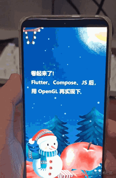
Soon I saw a funny comment:

Now that the clients are rolled up like this, just break the pot and supplement the implementation version of Android OpenGL. After all, graphics may be late, but it will never be absent.
The implementation effects are as follows (picture source). This wave really participated in the client Grand Slam of naked eye 3D in the community:
https://juejin.cn/post/6991409083765129229

2 Principle Introduction & advantages of OpenGL
The principle of naked eye 3D and other articles are disassembled very clearly. Based on the principle of not repeatedly building wheels, some contents in Nayuta and Fu Xi's articles are quoted here. Thank you again. https://juejin.cn/post/6991409083765129229 https://juejin.cn/post/6992169168938205191
The essence of naked eye 3D effect is to divide the whole picture structure into three layers: upper layer, middle layer and bottom layer. When the mobile phone rotates left and right up and down, the pictures of the upper layer and the lower layer move in the opposite direction, while the middle layer does not move, giving people a 3D feeling visually:
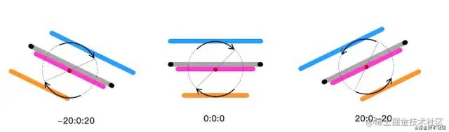
In other words, the effect is composed of the following three pictures:


Next, how to sense the rotation state of the mobile phone and move the three-layer pictures accordingly? Of course, the device itself is used to provide a variety of excellent sensors. The rotation state of the device can be obtained through the continuous callback of the sensor, and the UI can be rendered accordingly.
The author finally chose the OpenGL API on Android platform for rendering. The direct reason is that there is no need to copy the existing implementation schemes in the community.
Another important reason is that GPU is more suitable for graphics and image processing. There are a lot of scaling and displacement operations in naked eye 3D effects. Geometric transformations can be described in a matrix in the java layer and handed over to GPU for processing in the shader applet - therefore, in theory, the rendering performance of OpenGL is better than that of other schemes.
This article focuses on describing the idea of OpenGL rendering. Therefore, only part of the core code is shown below. Readers interested in the specific implementation can refer to the link at the end of the article.
3 specific implementation
1. Draw static pictures
First of all, you need to draw the three pictures statically in turn. This involves the use of a large number of OpenGL API s. If you are not familiar with it, you can read this section briefly to clarify your ideas.
First look at the shader code of vertex and slice shaders, which defines how image textures are rendered in the GPU:
// Vertex shader code
// Vertex coordinates
attribute vec4 av_Position;
// Texture coordinates
attribute vec2 af_Position;
uniform mat4 u_Matrix;
varying vec2 v_texPo;

void main() {
    v_texPo = af_Position;
    gl_Position =  u_Matrix * av_Position;
}
// Vertex shader code
// Vertex coordinates
attribute vec4 av_Position;
// Texture coordinates
attribute vec2 af_Position;
uniform mat4 u_Matrix;
varying vec2 v_texPo;

void main() {
    v_texPo = af_Position;
    gl_Position =  u_Matrix * av_Position;
}
After defining the Shader, initialize the Shader applet when creating GLSurfaceView (which can be understood as canvas in OpenGL) and load the image textures into the GPU in turn:
public class My3DRenderer implements GLSurfaceView.Renderer {

  @Override
  public void onSurfaceCreated(GL10 gl, EGLConfig config) {
      // 1. Load the shader applet
      mProgram = loadShaderWithResource(
              mContext,
              R.raw.projection_vertex_shader,
              R.raw.projection_fragment_shader
      );

      // ...

      // 2. Transfer 3 slice textures to GPU in turn
      this.texImageInner(R.drawable.bg_3d_back, mBackTextureId);
      this.texImageInner(R.drawable.bg_3d_mid, mMidTextureId);
      this.texImageInner(R.drawable.bg_3d_fore, mFrontTextureId);
  }
}
Next, define the size of the viewport. Because it is a 2D image transformation, and the aspect ratio of the cut image and the mobile phone screen is basically the same, simply define the orthogonal projection of an identity matrix:
public class My3DRenderer implements GLSurfaceView.Renderer {

    // Projection matrix
    private float[] mProjectionMatrix = new float[16];

    @Override
    public void onSurfaceChanged(GL10 gl, int width, int height) {
        // Set the viewport size, where you set the full screen
        GLES20.glViewport(0, 0, width, height);
        // The aspect ratio of the image and the screen is basically the same, which simplifies the processing and uses an identity matrix
        Matrix.setIdentityM(mProjectionMatrix, 0);
    }
}
The last is rendering. Readers need to understand that the logic of the rendering of the front, middle and rear images is basically the same, and there are only two differences: the image itself is different and the geometric transformation of the image is different.
public class My3DRenderer implements GLSurfaceView.Renderer {

    private float[] mBackMatrix = new float[16];
    private float[] mMidMatrix = new float[16];
    private float[] mFrontMatrix = new float[16];

    @Override
    public void onDrawFrame(GL10 gl) {
        GLES20.glClear(GLES20.GL_COLOR_BUFFER_BIT);
        GLES20.glClearColor(0.0f, 0.0f, 0.0f, 1.0f);

        GLES20.glUseProgram(mProgram);

        // Draw the background, middle view and foreground in turn
        this.drawLayerInner(mBackTextureId, mTextureBuffer, mBackMatrix);
        this.drawLayerInner(mMidTextureId, mTextureBuffer, mMidMatrix);
        this.drawLayerInner(mFrontTextureId, mTextureBuffer, mFrontMatrix);
    }

    private void drawLayerInner(int textureId, FloatBuffer textureBuffer, float[] matrix) {
        // 1. Bind image texture
        GLES20.glBindTexture(GLES20.GL_TEXTURE_2D, textureId);
        // 2. Matrix transformation
        GLES20.glUniformMatrix4fv(uMatrixLocation, 1, false, matrix, 0);
        // ...
        // 3. Execute drawing
        GLES20.glDrawArrays(GLES20.GL_TRIANGLE_STRIP, 0, 4);
    }
}
Refer to the code of drawLayerInner, which is used to draw single-layer images, where the textureId parameter corresponds to different images and the matrix parameter corresponds to different geometric transformations.
Now we have finished the static drawing of the image, and the effect is as follows:

Next, we need to access the sensor and define the geometric transformation of different levels of pictures to make the pictures move.
2. Make the picture move
First, we need to register the sensors on the Android platform, monitor the rotation status of the mobile phone, and get the rotation angle of the mobile phone's xy axis.
// 2.1 registered sensors
mSensorManager = (SensorManager) context.getSystemService(Context.SENSOR_SERVICE);
mAcceleSensor = mSensorManager.getDefaultSensor(Sensor.TYPE_ACCELEROMETER);
mMagneticSensor = mSensorManager.getDefaultSensor(Sensor.TYPE_MAGNETIC_FIELD);
mSensorManager.registerListener(mSensorEventListener, mAcceleSensor, SensorManager.SENSOR_DELAY_GAME);
mSensorManager.registerListener(mSensorEventListener, mMagneticSensor, SensorManager.SENSOR_DELAY_GAME);

// 2.2 continuously accept the rotating state
private final SensorEventListener mSensorEventListener = new SensorEventListener() {
    @Override
    public void onSensorChanged(SensorEvent event) {
        // ...  Omit specific code
        float[] values = new float[3];
        float[] R = new float[9];
        SensorManager.getRotationMatrix(R, null, mAcceleValues, mMageneticValues);
        SensorManager.getOrientation(R, values);
        // Deflection angle of x axis
        float degreeX = (float) Math.toDegrees(values[1]);
        // Deflection angle of y-axis
        float degreeY = (float) Math.toDegrees(values[2]);
        // Deflection angle of z axis
        float degreeZ = (float) Math.toDegrees(values[0]);

        // Get the rotation angle of xy axis and perform matrix transformation
        updateMatrix(degreeX, degreeY);
    }
};
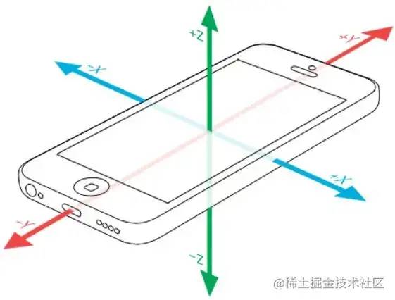
Note that because we only need to control the left, right and up and down movement of the image, we only need to pay attention to the deflection angles of the x-axis and y-axis of the device itself:
After you get the deflection angles of the x-axis and y-axis, you start to define the displacement of the image.
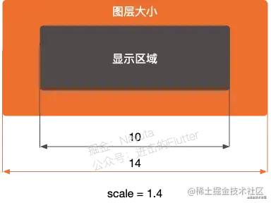
However, if the image is directly displaced, there will be no texture data on the other side of the image after displacement, resulting in black edges in the rendering result. In order to avoid this problem, we need to enlarge the image from the center point by default to ensure that the image will not exceed its own boundary in the process of image movement.
In other words, when we first entered, we must only see part of the picture. Set scale for each layer to enlarge the picture. The display window is fixed, so you can only see the middle of the picture at the beginning. (the middle layer can not be used, because the middle layer itself does not move, so it does not need to be enlarged)
The processing here refers to Nayuta's article, which has been clearly explained internally, and readers are strongly recommended to read it. https://juejin.cn/post/6991409083765129229#heading-4
Understanding this, we can understand that the effect of naked eye 3D is actually the transformation of scaling and displacement of images at different levels. The following is the code for obtaining geometric transformation respectively:
public class My3DRenderer implements GLSurfaceView.Renderer {

    private float[] mBackMatrix = new float[16];
    private float[] mMidMatrix = new float[16];
    private float[] mFrontMatrix = new float[16];

    /**
     * Gyro data callback to update the transformation matrix of each level
     *
     * @param degreeX x Axis rotation angle, the picture should move up and down
     * @param degreeY y Axis rotation angle, the picture should move left and right
     */
    private void updateMatrix(@FloatRange(from = -180.0f, to = 180.0f) float degreeX,
                              @FloatRange(from = -180.0f, to = 180.0f) float degreeY) {
        // ...  Other treatment

        // Background transformation
        // 1. Maximum displacement
        float maxTransXY = MAX_VISIBLE_SIDE_BACKGROUND - 1f;
        // 2. Displacement this time
        float transX = ((maxTransXY) / MAX_TRANS_DEGREE_Y) * -degreeY;
        float transY = ((maxTransXY) / MAX_TRANS_DEGREE_X) * -degreeX;
        float[] backMatrix = new float[16];
        Matrix.setIdentityM(backMatrix, 0);
        Matrix.translateM(backMatrix, 0, transX, transY, 0f);                    // 2. Translation
        Matrix.scaleM(backMatrix, 0, SCALE_BACK_GROUND, SCALE_BACK_GROUND, 1f);  // 1. Zoom
        Matrix.multiplyMM(mBackMatrix, 0, mProjectionMatrix, 0, backMatrix, 0);  // 3. Orthogonal projection

        // Mid range transformation
        Matrix.setIdentityM(mMidMatrix, 0);

        // Foreground transformation
        // 1. Maximum displacement
        maxTransXY = MAX_VISIBLE_SIDE_FOREGROUND - 1f;
        // 2. Displacement this time
        transX = ((maxTransXY) / MAX_TRANS_DEGREE_Y) * -degreeY;
        transY = ((maxTransXY) / MAX_TRANS_DEGREE_X) * -degreeX;
        float[] frontMatrix = new float[16];
        Matrix.setIdentityM(frontMatrix, 0);
        Matrix.translateM(frontMatrix, 0, -transX, -transY - 0.10f, 0f);            // 2. Translation
        Matrix.scaleM(frontMatrix, 0, SCALE_FORE_GROUND, SCALE_FORE_GROUND, 1f);    // 1. Zoom
        Matrix.multiplyMM(mFrontMatrix, 0, mProjectionMatrix, 0, frontMatrix, 0);  // 3. Orthogonal projection
    }
}
There are still a few details to deal with in this code.
3. Several counterintuitive details
3.1 rotation direction ≠ displacement direction
First of all, the rotation direction of the device is opposite to the displacement direction of the picture. For example, when the device rotates along the X axis, the picture corresponding to the front and rear scenes should move up and down for the user. Conversely, when the device rotates along the Y axis, the picture should move left and right (students who do not understand can refer to the gyro picture above for further understanding):
// The rotation direction of the device is opposite to the displacement direction of the picture
float transX = ((maxTransXY) / MAX_TRANS_DEGREE_Y) * -degreeY;
float transY = ((maxTransXY) / MAX_TRANS_DEGREE_X) * -degreeX;
// ...
Matrix.translateM(backMatrix, 0, transX, transY, 0f);
3.2 default rotation angle ≠ 0 °
Secondly, when defining the maximum rotation angle, the rotation angle = 0 ° cannot be regarded as the default value. What do you mean? When the rotation angle of Y axis is 0 °, that is, when degree y = 0, the height difference between the left and right of the device is 0 by default. This is in line with the user's usage habits and is relatively easy to understand. Therefore, we can define the maximum rotation angle between the left and right, such as y ∈ (- 45 °, 45 °). Beyond these two rotation angles, the picture will move to the edge.
However, when the X-axis rotation angle is 0 °, that is, degreeX = 0, it means that the height difference between the top and bottom of the device is 0. You can understand that the device is placed on a horizontal desktop, which is by no means in line with the usage habits of most users. In contrast, the device screen is more suitable for most scenes when it is parallel to people's face (degreeX = -90):

Therefore, the code needs to define the maximum rotation angle interval of X and Y axes separately:
private static final float USER_X_AXIS_STANDARD = -45f;
private static final float MAX_TRANS_DEGREE_X = 25f;   // Maximum rotation angle of X axis ∈ (- 20 °, - 70 °)

private static final float USER_Y_AXIS_STANDARD = 0f;
private static final float MAX_TRANS_DEGREE_Y = 45f;   // Maximum rotation angle of Y axis ∈ (- 45 °, 45 °)
After solving these counterintuitive details, we basically completed the effect of naked eye 3D.
4. Parkinson's syndrome?
It's almost done. Finally, we need to deal with the problem of 3D effect jitter:
As shown in the figure, because the sensor is too sensitive, even if the device is held smoothly, the slight changes in the three directions of XYZ will affect the user's actual experience and bring the user self doubt of Parkinson's syndrome.
To solve this problem, traditional OpenGL and Android API seem to be powerless, but someone on GitHub has provided another idea.
Students familiar with signal processing know that in order to provide a smooth form of signal by eliminating short-term fluctuations and retaining long-term development trend, low-pass filters can be used to ensure that signals below the cut-off frequency can pass and signals above the cut-off frequency cannot pass.
Therefore, someone established this warehouse to filter out small noise signals by adding low-pass filtering to Android sensors, so as to achieve a more stable effect:
https://github.com/Bhide/Low-Pass-Filter-To-Android-Sensors
private final SensorEventListener mSensorEventListener = new SensorEventListener() {
    @Override
    public void onSensorChanged(SensorEvent event) {
        // Low pass filtering is added to the data of the sensor
        if (event.sensor.getType() == Sensor.TYPE_ACCELEROMETER) {
            mAcceleValues = lowPass(event.values.clone(), mAcceleValues);
        }
        if (event.sensor.getType() == Sensor.TYPE_MAGNETIC_FIELD) {
            mMageneticValues = lowPass(event.values.clone(), mMageneticValues);
        }

        // ...  Omit specific code
        // Deflection angle of x axis
        float degreeX = (float) Math.toDegrees(values[1]);
        // Deflection angle of y-axis
        float degreeY = (float) Math.toDegrees(values[2]);
        // Deflection angle of z axis
        float degreeZ = (float) Math.toDegrees(values[0]);

        // Get the rotation angle of xy axis and perform matrix transformation
        updateMatrix(degreeX, degreeY);
    }
};
With the success, we finally achieved the expected results:

Source address
For all the source code of this article, please check here.
https://github.com/qingmei2/OpenGL-demo/blob/master/app/src/main/java/com/github/qingmei2/opengl_demo/c_image_process/processor/C06Image3DProcessor.java
reference resources
Finally, the relevant materials mentioned in this paper, thank the pioneers for their practice again.
Realization of naked eye 3D effect of free guest APP @ free front-end team
https://juejin.cn/post/6989227733410644005
Take it, you! Flutter free App naked eye 3D effect @ Nayuta
https://juejin.cn/post/6991409083765129229
Here comes the Compose version! Imitation free naked eye 3D effect @ Fu Xi
https://juejin.cn/post/6992169168938205191
GitHub: Low-Pass-Filter-To-Android-Sensors
https://github.com/Bhide/Low-Pass-Filter-To-Android-Sensors