STM32 library function development series article directory
Part I: program design and implementation of STM32F103ZET6 single chip microcomputer dual serial port mutual transmission
Part II: the simplest DIY Bluetooth smart car design scheme based on STM32 single chip microcomputer
preface
The simplest original core technology of the Internet of things DIY Bluetooth smart car design scheme based on STM32 single chip microcomputer.
There are various open source STM32 Bluetooth smart cars on the market, but there are complex and simple ones. If you want to get started with STM32 Bluetooth smart car quickly, this scheme will give you a fast and efficient scheme.
1, What is the simplest DIY Bluetooth smart car design scheme based on STM32 single chip microcomputer?
MCU beginners use serial port to debug programs is very convenient. What simulator and register are not as convenient and fast as serial port printing. In the first part, the STM32 serial port mutual sending program is introduced. Now the serial port communication is composed of serial port Bluetooth module and MCU. The debugging method involves the technology in the first part.
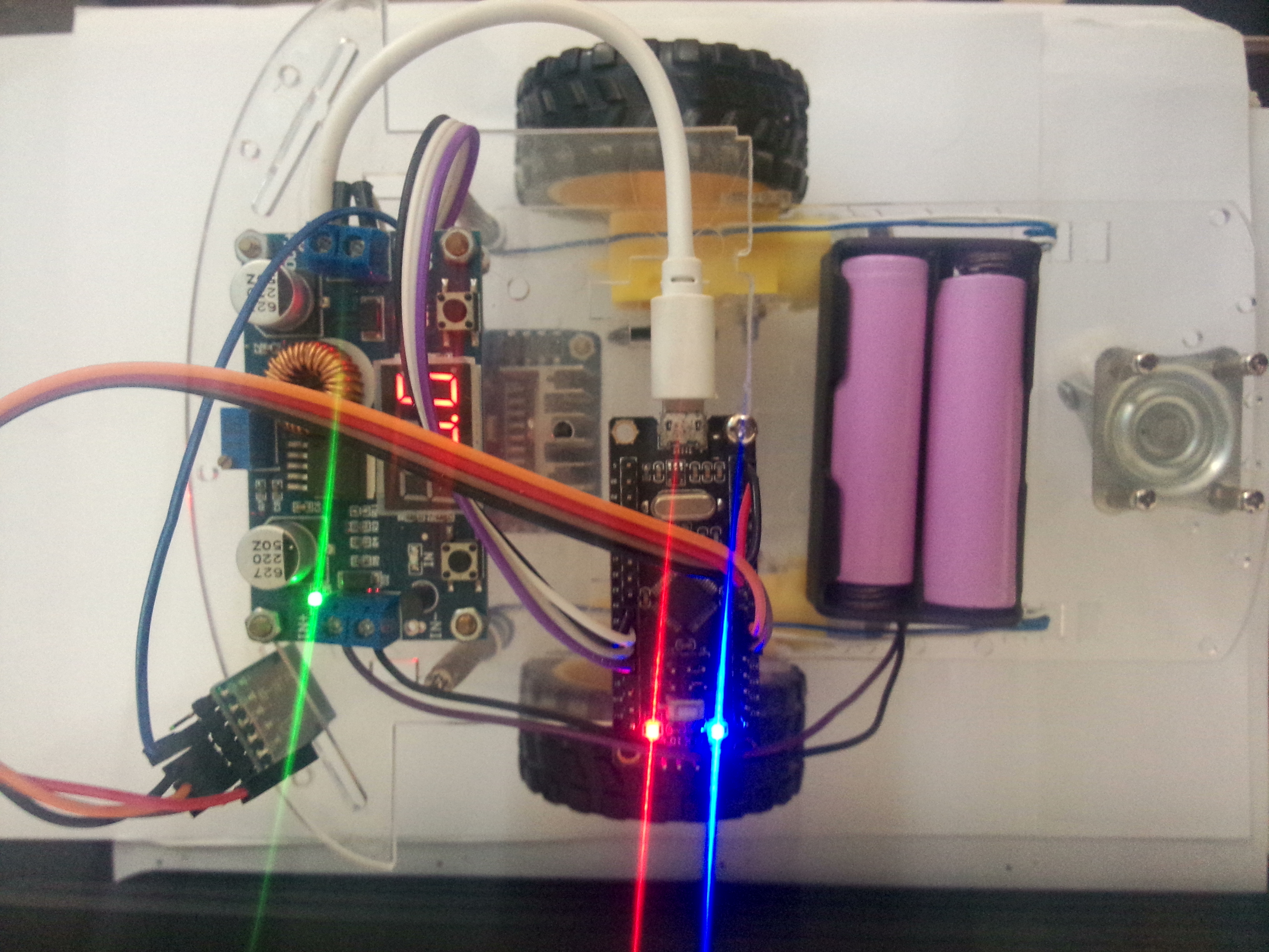
The first blog post in the column of intelligent small design of 51 single chip microcomputer: The simplest DIY 51 Bluetooth remote control car design scheme This paper describes how to make a wireless Bluetooth intelligent car with 51 single chip microcomputer. Some readers also think that taking a 51 as a smart car has too low scalability, so I launched an open source charging version of STM32 Bluetooth smart car this time. It adopts a double-layer transparent acrylic plate structure, uses a power supply with nixie tube display, L298N module with independent switch, one STM32F103C8T6 as the main control, and two 18650 high-energy lithium batteries for power supply, An HC05 serial port Bluetooth module, three copper pillars support the acrylic plate on the second floor. The whole car structure is designed and built by me manually, which looks like a work of art. Here's the family photo:
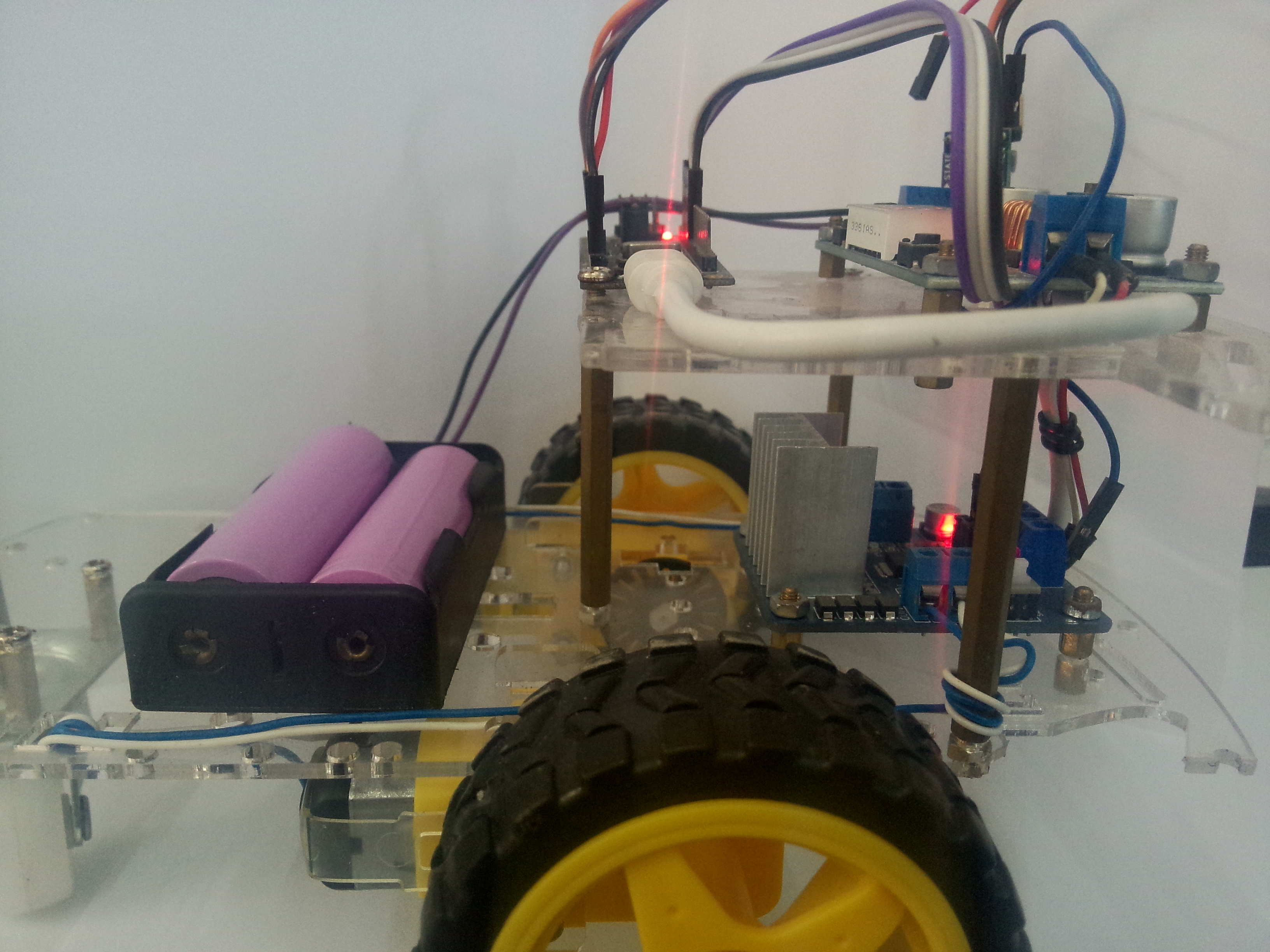
The first side shot:
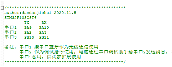
Function Description: the function expansion of the car has improved a lot. First, it supports the simultaneous use of three serial ports. I define serial port 1 to connect to the Bluetooth module, serial port 2 to be used for debugging, and serial port 3 to be extended by the buyer. It should be noted that stm32 triggers a serial port interrupt, which needs to be added \ r\n, and serial port 1 is linked to the Bluetooth module, The serial port 1 interrupt of STM32 must be received \ R \ nto trigger the serial port interrupt. Hexadecimal is 0d 0a. The data received by serial port 1 will be output to the computer debugging assistant through serial port 2. In this way, the program can be debugged with serial port 2 to see whether the Bluetooth of serial port 1 receives data. In addition, if you send data to serial port 2, serial port 2 will return the same data, At the same time, serial port 2 also sends data to serial port 1, which can also test whether the Bluetooth module can reply to the Bluetooth debugging assistant.
Youku video presentation address: https://v.youku.com/v_show/id_XNDk2MjQ4MTM3Mg==.html
Direct viewing
The simplest DIY Bluetooth smart car design scheme based on STM32 single chip microcomputer
2, Use steps
1. Prepare hardware
In fact, the only difference between this STM32 smart Bluetooth Car and the 51 smart Bluetooth car is that the core board has been replaced and other hardware remains the same, so buyers who don't understand can have a look The simplest DIY 51 Bluetooth remote control car design scheme
Now I'd like to list the hardware: buy the responding modules according to the physical drawing and assemble them into a car, L298N, power module, battery clip and 18650 battery, power transformer, STM32F103C8T6 MCU minimum system board, HC05 serial port Bluetooth module and car base.
2. Prepare a serial communication code
I use library function development, so the code directly uses the open source code in the first article.
The code is as follows (example):
#include "led.h"
#include "delay.h"
#include "key.h"
#include "sys.h"
#include "usart.h"
#include "usart2.h"

//Serial port experiment
//Technical support: daodan Jishui
 int main(void)
 {
 	u8 t;
	u8 len;
  u8 len2;
	delay_init();	    	 //Delay function initialization
	NVIC_Configuration(); 	 //Set NVIC interrupt packet 2: 2-bit preemption priority and 2-bit response priority
	uart_init(9600);	 //The serial port is initialized to 9600

  uart2_init(9600);
 	//LED_Init(); 			     // Led port initialization
	//KEY_Init();          // Initialize the hardware interface connected with the key
 	while(1)
	{
		if(USART_RX_STA&0x8000)
		{
			len=USART_RX_STA&0x3fff;//Get the length of the data received this time

			/* //Because I want to send back the data of the weather station, I can't directly return the data to the weather station, otherwise an error may occur
			printf("The data of computer send to serial port 1 is: \ r\n ");
			for(t=0;t<len;t++)
			{
				USART_SendData(USART1, USART_RX_BUF[t]);//The single chip microcomputer sends data to the computer through serial port 1
				while(USART_GetFlagStatus(USART1,USART_FLAG_TC)!=SET);//Wait for sending to end
			  //printf("\r\n Sending succeeded \ r\n "); / / insert newline
			}
      printf("\r\n");//Insert wrap
			*/


      u2_printf("computer send to The data of serial port 2 is:\r\n");
			for(t=0;t<len;t++)
			{
				USART_SendData(USART2, USART_RX_BUF[t]);//Forward the data received by serial port 1 to serial port 2 for output
				while(USART_GetFlagStatus(USART2,USART_FLAG_TC)!=SET);//Wait for sending to end
			}
			u2_printf("\r\n");//Insert wrap


			USART_RX_STA=0;
		}


		if(USART2_RX_STA&0x8000)
		{
			len2=USART2_RX_STA&0x3fff;//Get the length of the data received this time

      u2_printf("computer send to The data of serial port 2 is:\r\n");
			for(t=0;t<len2;t++)
			{
				USART_SendData(USART2, USART2_RX_BUF[t]);//MCU sends data to the computer through serial port 2
				while(USART_GetFlagStatus(USART2,USART_FLAG_TC)!=SET);//Wait for sending to end
			}
			u2_printf("\r\n");//Insert wrap


      //printf("the data of computer send to serial port 1 is: \ r\n");
      printf("\r\n");//As the beginning of the command response
			for(t=0;t<len2;t++)
			{
				USART_SendData(USART1, USART2_RX_BUF[t]);//Forward the data received by serial port 2 to serial port 1 for output
				while(USART_GetFlagStatus(USART1,USART_FLAG_TC)!=SET);//Wait for sending to end
			}
			printf("\r\n");//Insert wrap

			USART2_RX_STA=0;
		}
	}
 }
3. Modify the source code
Because the smart car is not only designed to send and receive serial port information, but also involves the analysis of instructions and the execution of wheel motor. Therefore, you need to add the following to the original code:
(1) The code of instruction parsing is as follows
if(USART_RX_STA&0x8000)
		{
			len=USART_RX_STA&0x3fff;//Get the length of the data received this time
			//printf("the data of computer send to serial port 1 is: \ r\n");
			for(t=0;t<len;t++)// Here, all the things sent by the computer to the serial port are returned
			{
				USART_SendData(USART1, USART_RX_BUF[t]);//MCU sends data to the computer through serial port 1?
				while(USART_GetFlagStatus(USART1,USART_FLAG_TC)!=SET);//Wait for sending to end
			//	Printf ("\ R \ nsending succeeded \ r\n")// Insert wrap

			}
			printf("\r\n");//Insert wrap
			//Add the logic of controlling the vehicle here
			//p1=strstr((const char*)USART3_RX_BUF,(const char*)"ID0:");
					if(strstr((const char*)USART_RX_BUF,"FFF")!=NULL){
						flag=0;
					}else if(strstr((const char*)USART_RX_BUF,"BBB")!=NULL){
						flag=1;
					}else if(strstr((const char*)USART_RX_BUF,"LLL")!=NULL){
						flag=2;
					}else if(strstr((const char*)USART_RX_BUF,"RRR")!=NULL){
						flag=3;
					}else if(strstr((const char*)USART_RX_BUF,"SSS")!=NULL){
						flag=4;
					}else  flag=4;
				switch (flag)
				{
				 case 0: {front(); u2_printf("FFF\r\n");printf("FFF\r\n");break;}//Serial port received forward
				 case 1: {back();u2_printf("BBB\r\n");printf("BBB\r\n");break;}
			   case 2: {left();u2_printf("LLL\r\n");printf("LLL\r\n");break; }
				 case 3: {right();u2_printf("RRR\r\n");printf("RRR\r\n");break;}
				 case 4: {stop();u2_printf("SSS\r\n"); printf("SSS\r\n");break;}
					 default:
						 stop();
					   u2_printf("SSS\r\n");
					   break;
				}
			  //USART_RX_STA=0;

			//End of vehicle control


      u2_printf("The data sent by MCU serial port 2 is:\r\n");
			for(t=0;t<len;t++)
			{
				USART_SendData(USART2, USART_RX_BUF[t]);//The single chip microcomputer sends data to the computer through serial port 2
				while(USART_GetFlagStatus(USART2,USART_FLAG_TC)!=SET);//Wait for sending to end
			}
			u2_printf("\r\n");


		   USART_RX_STA=0;
		}
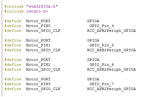
(2) The code of action execution is as follows
#include "output.h"
#include "delay.h"

void Motor_GPIO_Init(void)
{
GPIO_InitTypeDef Init_Instructure;
	RCC_APB2PeriphClockCmd(Motor_GPIO_CLK ,ENABLE );
	Init_Instructure.GPIO_Mode=GPIO_Mode_Out_PP;
	Init_Instructure.GPIO_Pin=Motor_PIN0;
	Init_Instructure.GPIO_Speed=GPIO_Speed_50MHz;
	GPIO_Init(Motor_PORT,&Init_Instructure );

	Init_Instructure.GPIO_Pin=Motor_PIN1;
	GPIO_Init(Motor_PORT,&Init_Instructure );

	Init_Instructure.GPIO_Pin=Motor_PIN2;
	GPIO_Init(Motor_PORT,&Init_Instructure );

	Init_Instructure.GPIO_Pin=Motor_PIN3;
	GPIO_Init(Motor_PORT,&Init_Instructure );

}

void back(void)
{
Motor_PIN0_0;
Motor_PIN1_1;

Motor_PIN2_1 ;
Motor_PIN3_0;

	delay_ms(1000);
	stop();


}

//PA0~3 connected to IN1~4 of L298N

void front(void)
{
Motor_PIN0_1;//PA0 set to 1
Motor_PIN1_0;//PA1 set to 0
Motor_PIN2_0;//PA2 set to 0
Motor_PIN3_1;//PA3 set to 1

	 delay_ms(1000);
	stop();
}

void left(void)
{

Motor_PIN0_1;
Motor_PIN1_0;

Motor_PIN2_0;
Motor_PIN3_0;

	delay_ms(200);
	stop();

}

void right(void)
{


Motor_PIN0_0;
Motor_PIN1_0;

Motor_PIN2_0;
Motor_PIN3_1;

  	delay_ms(200);
	  stop();

}


void stop(void)
{
Motor_PIN0_0;
Motor_PIN1_0;

Motor_PIN2_0;
Motor_PIN3_0;
}
3, Operation and commissioning
-
Wiring according to source code
-
-
Buy the responding modules according to the physical drawing and assemble them into a car, L298N, power module, battery clip and 18650 battery, power transformer, minimum system board of 51 single chip microcomputer, HC05 serial port Bluetooth module and car base
-
According to the source code wiring, burn the program into the MCU
The general wiring relationship is that the Bluetooth module is connected to the serial port of the single chip microcomputer: the Bluetooth module rxd is connected to the single chip microcomputer PA9
Txd is connected to the four in pins of single chip microcomputer PA10 and L298N, and the four in pins of single chip microcomputer PA4, Pa5, PA6 and PA7 are connected -
Install Android Bluetooth debugging assistant for mobile phone
-
Trolley power on
-
Open Bluetooth and Bluetooth debugging assistant
-
Search the Bluetooth module of the car and link the car Bluetooth
-
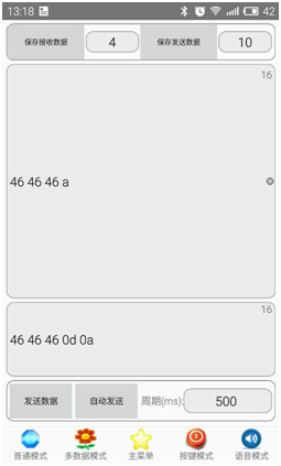
The hexadecimal instruction was sent because the car received the instruction with \ r\n as the end symbol
So the instruction is followed by hexadecimal 0d 0a
For example, FFF\r\n is forward, and the instruction conversion to hexadecimal is 46460d0a
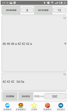
The following is backward: the BBB \ R \ ninstruction is converted to hexadecimal
Here's a left turn: LLL\r\n
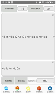
Last right turn: RRR\r\n
Now focus on the debugging process of serial port mutual transmission:
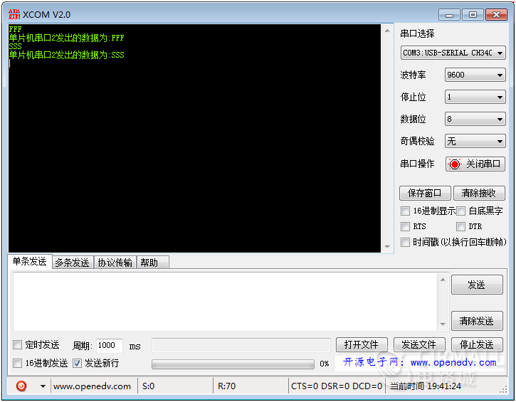
1. Start the trolley power supply, connect the USB to TTL cable to the serial port 2 of stm32 single chip microcomputer, use the mobile phone Bluetooth debugging assistant to control the trolley forward and send FFF, then print FFF on serial port 2, send SSS and print SSS. Description serial port 1 receives Bluetooth instructions and serial port 2 sends instructions, and the computer receives the information of serial port 2 and then prints it out.
2. Send the BBB to serial port 2 through the computer debugging assistant. It is found that the mobile phone Bluetooth debugging assistant receives the BBB, indicating that serial port 2 receives the BBB from serial port 1. The message sent by serial port 1 is transmitted to the mobile phone, and Bluetooth shows that the BBB is received.
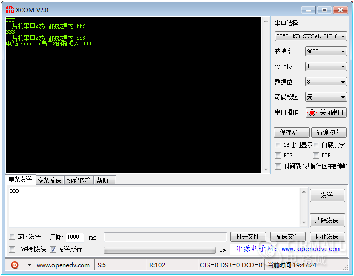
Summary: through 1 and 2, we realize mutual transmission through dual serial ports to debug the smart car.
summary
Through the above operation and commissioning, it is proved that the trolley is in good condition and meets the requirements put forward in the blog.
Some readers say: why not use the mobile app to control the smart car, but use the Bluetooth debugging assistant to send instructions to control it? In fact, I have launched the universal Bluetooth remote control, which can be installed on the Android phone to control the stm32 smart car, 51 smart car and steel patriot machine gun. Three control modes are supported: the first is command control; The second is direction key control; The third is gravity sensor control, which is equipped with Bluetooth intelligent search and link, command feedback display and other functions. Readers who need it please visit me: The simplest DIY universal Bluetooth device intelligent remote controller based on Android system.
Watch Youku video address: https://v.youku.com/v_show/id_XNDk2MDk5NDE5Ng==.html?spm=a2hbt.13141534.app.55!25!2555!255!25!25!255!25A
Direct viewing
stm32 intelligent Bluetooth Car Control
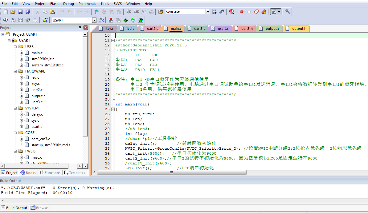
Screenshot of Trolley source code project:
Finally, the download address of this blog post code is attached: https://www.cirmall.com/circuit/21240/
Direct jump