1. Introduction
Recently, the virtual serial port function has been added to usb devices, and the number of usb endpoints used has increased from three to five. Coincidentally, the routine gave exactly less than three endpoints, so there was no error in the previous migration process, so it passed vaguely at that time, and endp0 was not studied_ Why is rxaddr 0x18.
Then today, it was found that in the case of multiple usb devices, the data transmission of the virtual serial port was garbled, which caused the problem.
Now the number of endpoints I have used has reached 5. The usb virtual serial port sends data to the PC. the data received by the PC is garbled. Compared with the routine code, there is no difference between myself and the routine code, so it forces me to find the problem. Fortunately, I solved my doubts after reading the post.

Post link:
2.ENDP0_RXADDR initial calculation basis
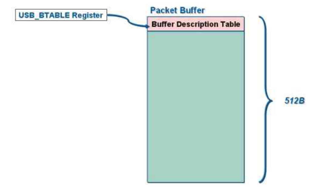
First, the stm32 single chip microcomputer has a 512 byte USB buffer, and then there is a Buffer Description Table in the USB, that is, we are on the USB_ A macro definition seen in the conf.h header file.
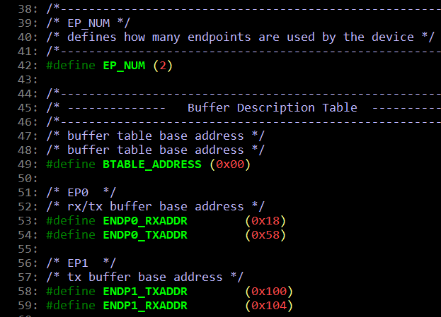
/* buffer table base address */
/* buffer table base address */
#define BTABLE_ADDRESS 		(0x00)
This Buffer Description Table is generally stored in the USB 512 byte buffer of the single chip microcomputer, and there is generally the starting position of the USB buffer, so we see the btable above_ The address macro defines 0x00, which is the starting position of the USB buffer.
Then let's talk about the contents and functions of the Buffer Description Table.
The existence of this table is that the cache address addr and cache length of each endpoint, that is, an endpoint will correspond to an addr+length, that is, it occupies 8 bytes.
The Buffer Description Table shares the 512 byte buffer with our USB sending and receiving, so when this table changes, the sending and receiving buffer size of the endpoints we can use will change.
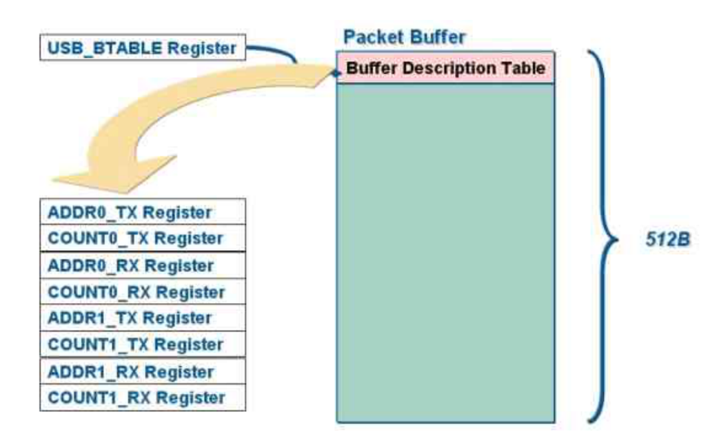
From the above figure, the more endpoints are used, the larger the table, and the smaller the remaining cache area.
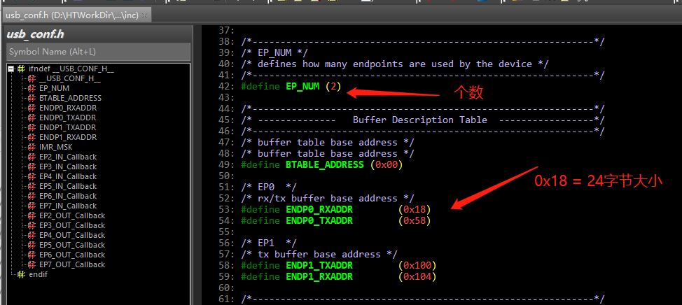
stm32USB routines use 2 or 3 endpoints, so they will end 0_ Rxaddr is defined as 0x18 (equal to 24 bytes). When two endpoints are used, Buffer Description Table occupies 2*(4+4) = 16Byte; When three endpoints are used, the Buffer Description Table occupies 3 * (4 + 4) = 24byte (that is, 0x18). That's what's given in the routine.
I now use five endpoints, so I calculate ENDP0_RXADDR = 0x28.
/*-------------------------------------------------------------*/
/* EP_NUM */
/* defines how many endpoints are used by the device */
/*-------------------------------------------------------------*/
#define EP_NUM  				 (5) / / it needs to be modified as 3 endpoints 0 + endpoint 1 + endpoint 2 = 3 endpoints 4 + 5

/*-------------------------------------------------------------*/
/* --------------   Buffer Description Table  -----------------*/
/*-------------------------------------------------------------*/
/* buffer table base address */
/* buffer table base address */
#define BTABLE_ADDRESS 		(0x00)

/* EP0  */
/* rx/tx buffer base address */
#define ENDP0_ Rxaddr (0x28) / / this starting address = (4+4)*EP_NUM = 40 = 0x48
#define ENDP0_ Txaddr (0x68) / / increment by 64Byte, that is, 0x40

/* EP1  */
/* tx buffer base address */
#define ENDP1_TXADDR        (0xA8)

/* EP2  */
/* tx buffer base address */
#define ENDP2_TXADDR        (0xE8)
#define ENDP2_RXADDR        (0x128)

/* EP3  */
/* tx buffer base address */
#define ENDP3_TXADDR        (0x168)

/* EP4  */
/* tx buffer base address */
#define ENDP4_TXADDR        (0x1A8)
#define ENDP4_RXADDR        (0x1E8)
After modifying this, the problem of USB multi-channel virtual serial port random code is solved.
Thank you for the introduction of this document:
STM32F103 USB Packet Buffer 512: STM32F103 USB Packet Buffer 512 - Douding network
over!