I Theoretical overview
- Introduction to W5500 Ethernet module:
Niren_W5500 module is an Ethernet module based on WIZnet W5500 chip, which is the successor of clay figurine electronics Niren_W5100 module is an Ethernet module with better performance and higher cost performance. Module integrated hardware TCP/IP protocol: internal 32K byte memory as TX/RX cache: support 10/100Mbps transmission rate; Support the simultaneous operation of 8 independent ports; At the same time, the module also supports 3.3V or 5V power supply. When 5V power supply, it can also output 3.3V power supply, which is convenient for users to use in different single chip microcomputer systems; The communication mode between module and MCU system is simple and convenient SPI communication.
- Module pin arrangement menu:
| Row pin identification | Function description | Row pin identification | Function description |
|---|---|---|---|
| 3.3V | 3.3V power input pin | 5V | 5V power input pin |
| MISO | SPI master input slave output pin | GND | Power ground pin |
| MOSI | SPI master output slave input pin | RST | W5500 hardware initialization pin (active at low level) |
| SCS | SPI SLAVE select pin (active at low level) | INT | W5500 interrupt pin (active at low level) |
| SCLK | SPI clock pin | NC | Hang in the air |
- Introduction to Modbus
Modbus is a serial communication protocol developed by Modicon in 1979. It was originally designed for the company's programmable logic controller (PLC). MODBUS is an open protocol that supports serial devices using RS232/RS485/RS422 protocols, as well as modems. Its simplicity and the fact that manufacturers can incorporate it into their products free of charge make it the most popular way to connect industrial electronic devices.
The main reasons why Modbus is more widely used than other communication protocols are as follows:
Publicly published without copyright requirements;
Easy to deploy and maintain;
For suppliers, there are no many restrictions on modifying and moving local bits or bytes;
Modbus transmits data through a serial line between devices. The simplest setup is to use a serial cable to connect the serial ports on two devices (master and slave).
The data is transmitted in a sequence of 1 and 0 called bits. Each bit is sent as a voltage. 0 is sent as a positive voltage and 1 is sent as a negative voltage.
- Modbus/TCP protocol
| Function code | effect |
|---|---|
| 01 | Read coil status |
| 02 | Read input status |
| 03 | Read hold register |
| 04 | Read input register |
| 05 | Forced single coil |
| 06 | Preset single register |
| 07 | Read exception status |
| 08 | Loopback diagnostic verification |
| 09 | Programming (484 only) |
| 0A | Control inquiry |
| 0B | Read event count |
| 0C | Read communication event record |
| 0D | Programming (184 / 384 / 484 / 584, etc.) |
| 0E | seek |
| 0F | Forced multi coil |
| 10 | Preset multi coil |
| 11 | Report multiple registers |
| 12 | Enables the host to simulate programming functions |
| 13 | Reset communication link |
| 14 | Read general parameters |
| 15 | Write general parameters |
| 16 | Mask write register |
| 17 | Read / write multiple registers |
IGMP Query
00 6D 00 00 00 06 01 03 00 00 00 01
00 6D query No
00 00 agreement
00 06 packet length
01 equipment No
03 function code
00 00 start address
00 01 number of query registers
response message
00 6D 00 00 00 05 01 03 02 00 17
00 6D query No
00 00 agreement
00 05 packet length
01 device address
03 function code
02 data length
00 17 data value
II TCP data communication
Link: https://pan.baidu.com/s/1ninW1lpO94fl2GtDWx5csg
Extraction code: 7yqt
The debugging tool uses tcpudpdebug102 in the compressed package_ Setup, self installation
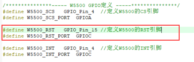
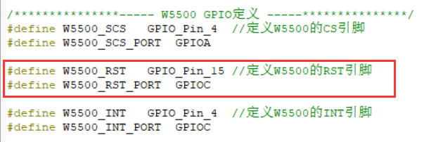
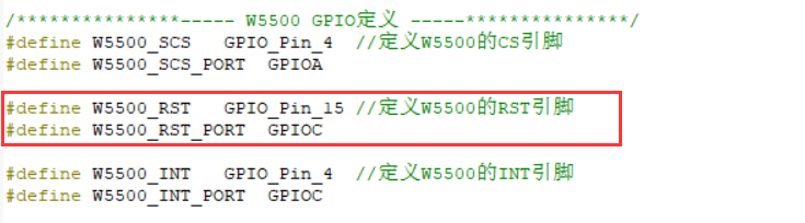
Connection method between STM32 and W5500
PC15->W5500_ Rst (PC5 is used in the source program, and this pin is not modified to PC15)
PC4->W5500_ Int (this pin may not be connected when using the routine of register query mode, and other routines may involve modifying the pin)
PA4->W5500_SCS
PA5->W5500_SCK
PA6->W5500_MISO
PA7->W5500_MOSI
For the debugging process of specific routines, please refer to Niren in the compressed package_ W5500 Module User Manual (open with Adobe Reader) pdf file.
- Modify the project code according to your own IP address
UDP: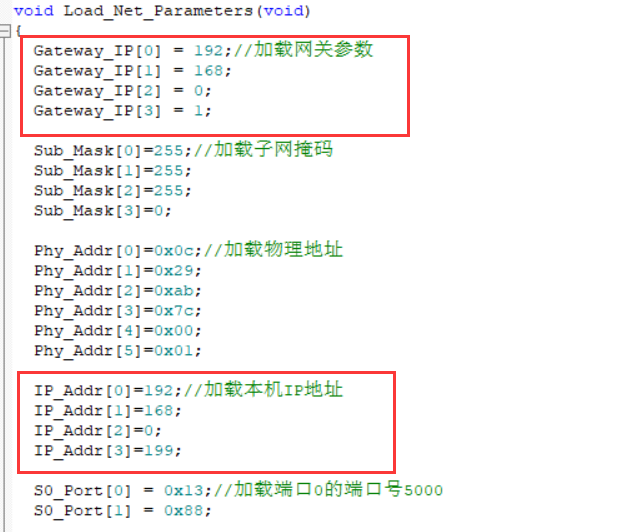
Server:
client:
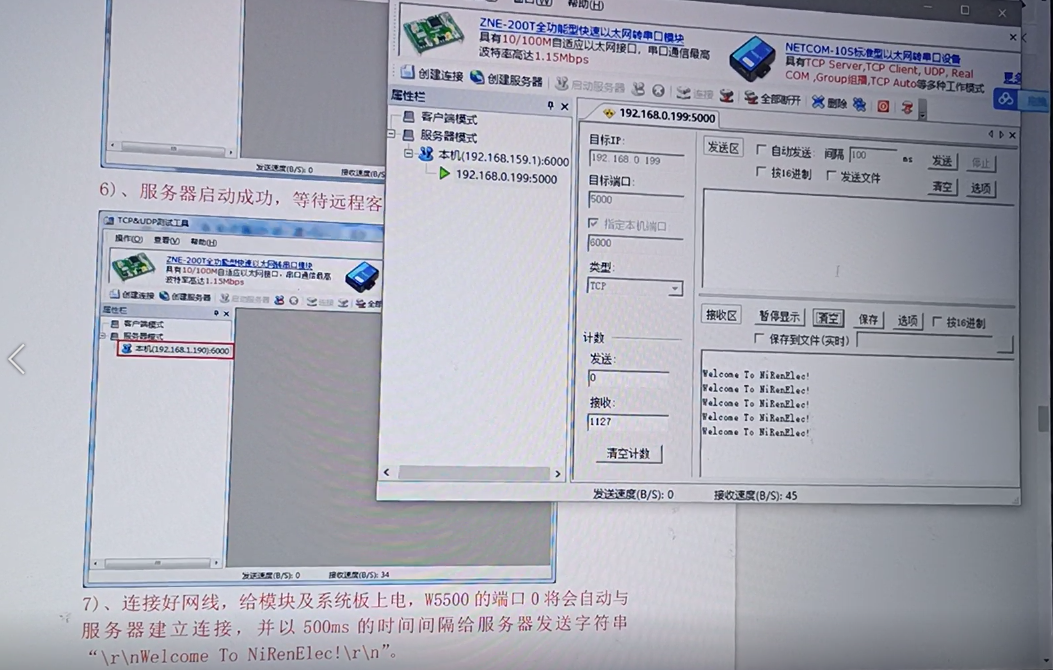
Here, I debugged the UDP mode, server mode and client mode routines in the query register mode. The debugging results are as follows:
UDP:
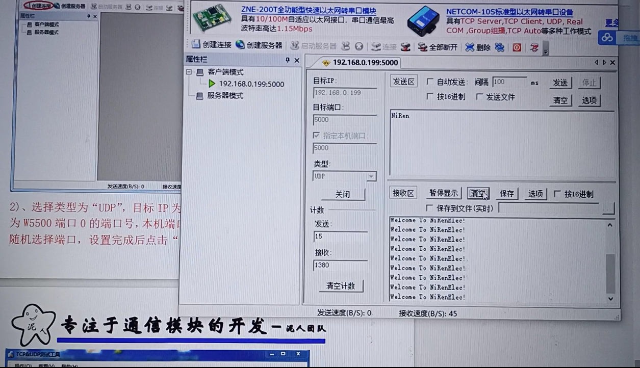
client:
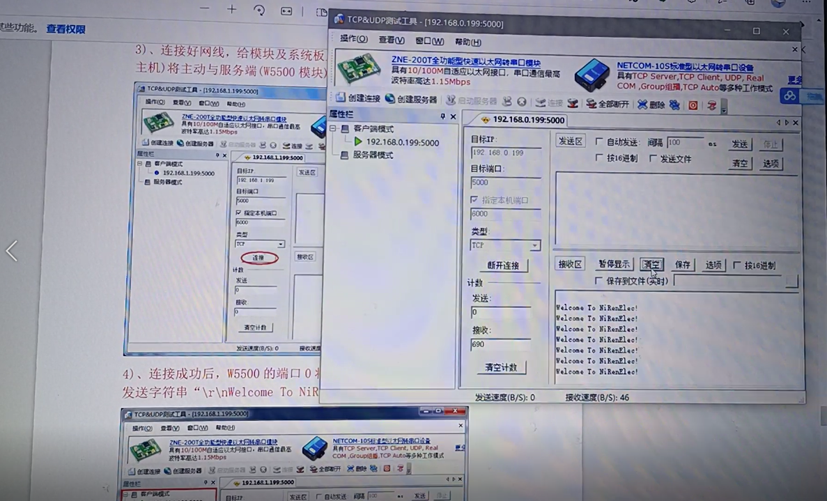
The server:
III STM32+W5500+modbus protocol programming
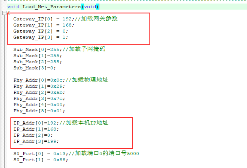
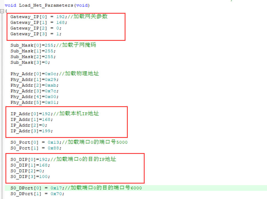
- Initialize slave network:
/* W5500 configuration */
void W5500_Configuration()
{
	unsigned char array[6];

	GPIO_SetBits(GPIO_W5500_RST_PORT, GPIO_W5500_RST_Pin);//Pull up
	Delay_ms(100);    /*delay 100ms Delay using systick 1ms time base*/
    //Waiting for Ethernet link
	while((Read_1_Byte(PHYCFGR)&LINK)==0); 		/* Waiting for Ethernet Link */

	Write_1_Byte(MR, RST);//Write one byte to W5500 general register
	Delay_ms(20);		/*delay 20ms */

	/* Set Gateway IP as: 192.168.1.1 */
	array[0]=192;
	array[1]=168;
	array[2]=0;
	array[3]=1;
	Write_Bytes(GAR, array, 4);//Set gateway IP

	/* Set Subnet Mask as: 255.255.255.0 */
	array[0]=255;
	array[1]=255;
	array[2]=255;
	array[3]=0;
	Write_Bytes(SUBR, array, 4);//Set subnet mask

	/* Set MAC Address as: 0x48,0x53,0x00,0x57,0x55,0x00 */
	array[0]=0x48;
	array[1]=0x53;
	array[2]=0x00;
	array[3]=0x57;
	array[4]=0x55;
	array[5]=0x00;
	Write_Bytes(SHAR, array, 6);//Set MAC address

	/* Set W5500 IP as: 192.168.1.128 */
	array[0]=192;
	array[1]=168;
	array[2]=0;
	array[3]=199;
	Write_Bytes(SIPR, array, 4);//Set IP address of W5500
}
Simple response function:
void Process_Socket_Data(SOCKET s)
{
	int len;
	unsigned char msg[11]={0x00,0x00,0x00 ,0x00, 0x00, 0x05, 0x01, 0x03, 0x02, 0x00, 0x70};
	len=sizeof(msg);
	unsigned short size;
	size=Read_SOCK_Data_Buffer(s, Rx_Buffer);
	memcpy(Tx_Buffer, Rx_Buffer, size);

	//Print query message
	for (int j=0;j<size;j++){
		 printf("0x%02X ",Tx_Buffer[j]);
	}

	//Write response message
	//Inspection code
	msg[0]=Tx_Buffer[0];
	msg[1]=Tx_Buffer[1];

	//agreement
	msg[2]=0x00;
	msg[3]=0x00;

	//Packet length
	msg[4]=0x00;
	msg[5]=0x05;

	//Equipment number
	msg[6]=Tx_Buffer[6];
	//Function code
	msg[7]=Tx_Buffer[7];
	//Data length
	msg[8]=0x02;

	//Lower eight
	msg[10]=data&0XFF;
	//High eight
	msg[9]=data>>8;

	memcpy(Tx_Buffer, msg, len);
	//Send response message
	Write_SOCK_Data_Buffer(0, Tx_Buffer, len);
	data++;
}
- The main function waits for a loop:
 while (1)
  {
		W5500_Socket_Set();//W5500 port initialization configuration

		W5500_Interrupt_Process();//W5500 interrupt handler framework

		if((S0_Data & S_RECEIVE) == S_RECEIVE)//If Socket0 receives data
		{
			S0_Data&=~S_RECEIVE;
			Process_Socket_Data(0);//The W5500 receives and sends the received data
		}
		//Slave status flag
		HAL_GPIO_TogglePin(GPIOC,GPIO_PIN_13);

  }
IV web service of STM32+W5500
main function:
int main(void)
{
	Systick_Init(72);//System clock initialization
	GPIO_Configuration(); //GPIO configuration
	USART1_Init(); //Serial port initialization: 115200@8-n-1
	printf("W5500 EVB initialization over.\r\n");
	Reset_W5500();
	WIZ_SPI_Init();//W5500 related pin configuration
	printf("W5500 initialized!\r\n");
	if(GPIO_ReadInputDataBit(GPIOB,GPIO_Pin_7))
	{
		DefaultSet();//Factory value
	}
	else
	{
 		get_config();//read config data from flash
	}
	printf("Firmware ver%d.%d\r\n",ConfigMsg.sw_ver[0],ConfigMsg.sw_ver[1]);
	if(ConfigMsg.debug==0) ConfigMsg.debug=1;

	set_network();//Configure network information
	printf("Network is ready.\r\n");
	while(1)
	{
		if(ConfigMsg.JTXD_Control == 0)
		  	do_http();//Open http service
		else
		  	JTXD_do_http();
		if(reboot_flag)
			NVIC_SystemReset();//Initiate system reset request to reset MCU
//        reboot();

	}
}
GPIO initialization function:
void GPIO_Configuration(void)
{
  GPIO_InitTypeDef GPIO_InitStructure;
  RCC_APB2PeriphClockCmd(RCC_APB2Periph_GPIOA |RCC_APB2Periph_GPIOB |RCC_APB2Periph_GPIOC|RCC_APB2Periph_AFIO , ENABLE);
  // Port A output
  GPIO_InitStructure.GPIO_Pin =GPIO_Pin_0|GPIO_Pin_1| GPIO_Pin_2 |GPIO_Pin_3;
  GPIO_InitStructure.GPIO_Speed = GPIO_Speed_50MHz;
  GPIO_InitStructure.GPIO_Mode = GPIO_Mode_Out_PP;
  GPIO_Init(GPIOA, &GPIO_InitStructure);

  // Port B output;
  GPIO_InitStructure.GPIO_Pin = GPIO_Pin_9;
  GPIO_InitStructure.GPIO_Speed = GPIO_Speed_50MHz;
  GPIO_InitStructure.GPIO_Mode = GPIO_Mode_Out_PP;
  GPIO_Init(GPIOB, &GPIO_InitStructure);
  GPIO_SetBits(GPIOB, GPIO_Pin_9);
  // Port C input
  GPIO_InitStructure.GPIO_Pin = GPIO_Pin_7;//Control flash
  GPIO_InitStructure.GPIO_Speed = GPIO_Speed_50MHz;
  GPIO_InitStructure.GPIO_Mode = GPIO_Mode_IPU;
  GPIO_Init(GPIOB, &GPIO_InitStructure);
  GPIO_SetBits(GPIOB, GPIO_Pin_7);
}
W5500 related configuration:
void WIZ_SPI_Init(void)
{
	SPI_InitTypeDef   SPI_InitStructure;
  GPIO_InitTypeDef GPIO_InitStructure;
  RCC_APB1PeriphClockCmd(RCC_APB1Periph_SPI2, ENABLE);
  RCC_APB2PeriphClockCmd( RCC_APB2Periph_GPIOB |RCC_APB2Periph_AFIO , ENABLE);
  // Port B output
  GPIO_InitStructure.GPIO_Pin = GPIO_Pin_12;
  GPIO_InitStructure.GPIO_Speed = GPIO_Speed_50MHz;
  GPIO_InitStructure.GPIO_Mode = GPIO_Mode_Out_PP;
  GPIO_Init(GPIOB, &GPIO_InitStructure);
  GPIO_SetBits(GPIOB, GPIO_Pin_12);
  /* Configure SPIy pins: SCK, MISO and MOSI */
  GPIO_InitStructure.GPIO_Pin = GPIO_Pin_13| GPIO_Pin_14| GPIO_Pin_15;
  GPIO_InitStructure.GPIO_Speed = GPIO_Speed_50MHz;
  GPIO_InitStructure.GPIO_Mode = GPIO_Mode_AF_PP;
  GPIO_Init(GPIOB, &GPIO_InitStructure);
	  /* SPI Config -------------------------------------------------------------*/
	  SPI_InitStructure.SPI_Direction = SPI_Direction_2Lines_FullDuplex;
	  SPI_InitStructure.SPI_Mode = SPI_Mode_Master;
	  SPI_InitStructure.SPI_DataSize = SPI_DataSize_8b;
	  SPI_InitStructure.SPI_CPOL = SPI_CPOL_Low;
	  SPI_InitStructure.SPI_CPHA = SPI_CPHA_1Edge;
	  SPI_InitStructure.SPI_NSS = SPI_NSS_Soft;
	  SPI_InitStructure.SPI_BaudRatePrescaler = SPI_BaudRatePrescaler_4;
	  SPI_InitStructure.SPI_FirstBit = SPI_FirstBit_MSB;
	  SPI_InitStructure.SPI_CRCPolynomial = 7;

	  SPI_Init(SPI2, &SPI_InitStructure);
	  SPI_Cmd(SPI2, ENABLE);
}
http request:
void do_http(void)
{
  uint8 ch=SOCK_HTTP;
  uint16 len;

  st_http_request *http_request;
  memset(rx_buf,0x00,MAX_URI_SIZE);
  http_request = (st_http_request*)rx_buf;		// struct of http request
  /* http service start */
  switch(getSn_SR(ch))
  {
    case SOCK_INIT:
      listen(ch);
      break;
    case SOCK_LISTEN:
      break;
    case SOCK_ESTABLISHED:
    //case SOCK_CLOSE_WAIT:
      if(getSn_IR(ch) & Sn_IR_CON)
      {
        setSn_IR(ch, Sn_IR_CON);
      }
      if ((len = getSn_RX_RSR(ch)) > 0)
      {
        len = recv(ch, (uint8*)http_request, len);
        *(((uint8*)http_request)+len) = 0;
        proc_http(ch, (uint8*)http_request); // request is processed
        disconnect(ch);
      }
      break;
    case SOCK_CLOSE_WAIT:
      if ((len = getSn_RX_RSR(ch)) > 0)
      {
        //printf("close wait: %d\r\n",len);
        len = recv(ch, (uint8*)http_request, len);
        *(((uint8*)http_request)+len) = 0;
        proc_http(ch, (uint8*)http_request); // request is processed
      }
      disconnect(ch);
      break;
    case SOCK_CLOSED:
      socket(ch, Sn_MR_TCP, 80, 0x00);    /* reinitialize the socket */
      break;
    default:
    break;
  }// end of switch
}

void JTXD_do_http(void)
{
  uint8 ch=SOCK_HTTP;
  uint16 len;

  st_http_request *http_request;
  memset(rx_buf,0x00,MAX_URI_SIZE);
  http_request = (st_http_request*)rx_buf;		// struct of http request

  /* http service start */
  switch(getSn_SR(ch))
  {
    case SOCK_INIT:
      listen(ch);
      break;
    case SOCK_LISTEN:

      break;
    case SOCK_ESTABLISHED:
    //case SOCK_CLOSE_WAIT:
      if(getSn_IR(ch) & Sn_IR_CON)
      {
        setSn_IR(ch, Sn_IR_CON);
      }
      if ((len = getSn_RX_RSR(ch)) > 0)
      {
        len = recv(ch, (uint8*)http_request, len);
        *(((uint8*)http_request)+len) = 0;
        JTXD_proc_http(ch, (uint8*)http_request); // request is processed
        disconnect(ch);
      }
      break;
    case SOCK_CLOSE_WAIT:
      if ((len = getSn_RX_RSR(ch)) > 0)
      {
        //printf("close wait: %d\r\n",len);
        len = recv(ch, (uint8*)http_request, len);
        *(((uint8*)http_request)+len) = 0;
        JTXD_proc_http(ch, (uint8*)http_request); // request is processed
      }
      disconnect(ch);
      break;
    case SOCK_CLOSED:
      socket(ch, Sn_MR_TCP, 80, 0x00);    /* reinitialize the socket */
      break;
    default:
    break;
  }// end of switch
}
explain:
The initial IP address is 192.168 0.199, switch between the default value and flash through the operation of PB7, write the set parameters to flash, w5500 is connected to SPI2, and the single chip microcomputer is stm32f103c8t6.
The first web page does not have any permission to modify, only enter the login password (initial password: 123456)
Or universal password: 765997) enter the modification page to modify parameters, including login password.
The browser uses IE.
V Reference link
STM32+W5500 network communication
STM32+W5500 Ethernet module
STM32 + w5500 + freemodbus Modbus TCP protocol function realization, project file download
Based on stm32_ DM9000_ UIP_ The Modbus TCP function of freemodbus realizes Engineering Download
web service made by STM32F103 W5500