preface:
First, understand what serial communication is (from punctual atomic data).
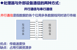
(1) Parallel communication VS serial communication

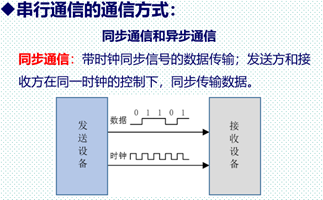
(2) Synchronous communication VS asynchronous communication

(3) . transmission direction


(4) Introduction to UART serial port
UART is a universal asynchronous receiver transmitter using asynchronous serial communication. It converts parallel data into serial data for transmission when sending data, and converts the received serial data into parallel data when receiving data. UART serial communication requires two signal lines, one for serial transmission and the other for serial reception. A frame of UART data in the process of sending or receiving is composed of four parts: start bit, data bit, parity bit and stop bit, as shown in the figure.
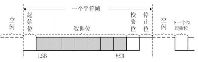
The start bit marks the beginning of a frame of data, the stop bit marks the end of a frame of data, and the data bit is the valid data in a frame of data. The check bits are divided into odd check and even check, which are used to check whether there are errors in the data transmission process. During odd check, the sender shall make the sum of the number of 1 in the data bit and the number of 1 in the check bit odd; When receiving data, the receiver checks the number of 1. If it is not an odd number, it indicates that there is an error in the data transmission process. Similarly, even check whether the number of 1 is even.
The data format and transmission rate during UART communication can be set. In order to correctly communicate, the sending and receiving parties shall agree and follow the same settings. 5, 6, 7 and 8 data bits can be selected, of which 8 data bits are the most commonly used. In practical application, 8 data bits are generally selected; The check bit can select odd check, even check or no check bit; The stop bit can be 1 bit (default), 1.5 or 2 bits. The rate of serial communication is expressed by baud rate, which represents the number of bits of binary data transmitted per second. The unit is bps (bit / second). The commonly used baud rates are 9600, 19200, 38400, 57600 and 115200.
After setting the data format and transmission rate, UART is responsible for the serial parallel conversion of data, and the signal transmission is realized by the external driving circuit. The transmission process of electrical signal has different level standards and interface specifications. The interface standards for asynchronous serial communication include RS232, RS422, RS485, etc. they define different electrical characteristics of the interface, such as RS-232 is single ended input and output, and RS-422/485 is differential input and output.
RS232 interface standard appeared earlier and can realize full duplex working mode, that is, data transmission and reception can be carried out at the same time. When the transmission distance is short (no more than 15m), RS232 is the most commonly used interface standard for serial communication. The most common interface type of RS-232 standard serial port is DB9. Industrial computers used in the field of industrial control are generally equipped with multiple serial ports, and many old desktop computers are also equipped with serial ports. However, notebook computers and newer desktop computers do not have serial ports. They generally realize serial communication with external devices through USB to serial port cable. Because the RS232 serial port of DB9 interface type occupies a large space, many systems have selected the USB to TTL scheme, use CH340 chip to realize the function of USB bus to UART, and communicate with the host computer through Mini USB interface.
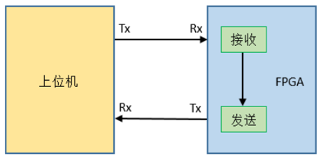
1, Physical layer
Realize the data loop between the host computer and FPGA serial port. That is, the upper computer sends data to FPGA through the serial port debugging assistant, and FPGA receives data through the serial port and connects it
The received data is sent to the upper computer to complete the serial port data loopback.
First, the data format and baud rate of serial communication should be determined. Here, select a common mode of serial port. The data bit is 8 bits, the stop bit is 1 bit, there is no check bit, and the baud rate is 115200bps. The sequence diagram of transmitting one frame of data is shown in the figure:

Data reception:
module uart_recv(
    input			  sys_clk,
    input             sys_rst_n,

    input             uart_rxd,  //Receive serial data
    output  reg       uart_done, //Receive a frame of data completion flag
    output  reg [7:0] uart_data  //Output parallel data
    );


parameter  CLK_FREQ = 50000000;  //System clock frequency: 50M pulses per second
parameter  UART_BPS = 115200;    //Serial port baud rate transmits 115200 data bits per second
localparam BPS_CNT  = CLK_FREQ/UART_BPS;  //Define internal variable BPS_CNT is the system clock frequency divided by the baud rate, that is, how many clock cycles it takes to send a data bit (1 bit).
                                          //Due to the slow transmission rate of the serial port, its baud rate cycle is obtained by counting the system clock.
                                          //Count BPS for system clock_ CNT times, you can get the baud rate cycle of the serial port.


reg        uart_rxd_d0;
reg        uart_rxd_d1;
reg [15:0] clk_cnt;     //System clock counter, which counts BPS of system clock_ CNT times, i.e. 1 bit data is sent
reg [ 3:0] rx_cnt;      //Receive data counter
reg        rx_flag;
reg [ 7:0] rxdata;

wire       start_flag;

//Capture UART from serial input port_ Falling edge of RXD
assign  start_flag = uart_rxd_d1 & (~uart_rxd_d0);

always @(posedge sys_clk or negedge sys_rst_n) begin
    if (!sys_rst_n) begin
        uart_rxd_d0 <= 1'b0;
        uart_rxd_d1 <= 1'b0;
    end
    else begin
        uart_rxd_d0  <= uart_rxd;
        uart_rxd_d1  <= uart_rxd_d0;
    end
end

//Rx for receiving process_ Flag signal is marked
always @(posedge sys_clk or negedge sys_rst_n) begin
    if (!sys_rst_n)
        rx_flag <= 1'b0;
    else begin
        if(start_flag)
            rx_flag <= 1'b1;
        else if((rx_cnt == 4'd9)&&(clk_cnt == BPS_CNT/2))
            rx_flag <= 1'b0;                             //rx_ The flag continues to the middle of the 10th bit (stop bit) and stops the receiving process
        else
            rx_flag <= rx_flag;
    end
end

Enter the sending process and the counter works
always @(posedge sys_clk or negedge sys_rst_n) begin
    if (!sys_rst_n) begin
        clk_cnt <= 16'd0;
        rx_cnt  <= 4'd0;
    end
    else if ( rx_flag ) begin                 //rx_ The flag signal is pulled high, the receiving process starts, and the counter works
            if (clk_cnt < BPS_CNT - 1) begin
                clk_cnt <= clk_cnt + 1'b1;
                rx_cnt  <= rx_cnt;
            end
            else begin
                clk_cnt <= 16'd0;
                rx_cnt  <= rx_cnt + 1'b1;     //clk_cnt count to BPS_CNT,rx_cnt plus 1
            end
        end
     else begin
         clk_cnt <= 16'd0;   //rx_ The flag signal is pulled low, the receiving process is completed, and the counter is cleared
         rx_cnt  <= 4'd0;
     end
end

//The serial data is converted into parallel data and stored in the internal variable rxdata
always @(posedge sys_clk or negedge sys_rst_n) begin
    if ( !sys_rst_n)
        rxdata <= 8'd0;
    else if(rx_flag)
        if (clk_cnt == BPS_CNT/2) begin
            case ( rx_cnt )
             4'd1 : rxdata[0] <= uart_rxd_d1;
             4'd2 : rxdata[1] <= uart_rxd_d1;
             4'd3 : rxdata[2] <= uart_rxd_d1;
             4'd4 : rxdata[3] <= uart_rxd_d1;
             4'd5 : rxdata[4] <= uart_rxd_d1;
             4'd6 : rxdata[5] <= uart_rxd_d1;
             4'd7 : rxdata[6] <= uart_rxd_d1;
             4'd8 : rxdata[7] <= uart_rxd_d1;   //Start bit 0 and stop bit 1 are removed
             default:;
            endcase
        end
        else
            rxdata <= rxdata;
    else
        rxdata <= 8'd0;
end

//Receiving module output: parallel signal transmission, and the receiving enable is pulled high
always @(posedge sys_clk or negedge sys_rst_n) begin
    if (!sys_rst_n) begin
        uart_data <= 8'd0;
        uart_done <= 1'b0;
    end
    else if(rx_cnt == 4'd9) begin
        uart_data <= rxdata;
        uart_done <= 1'b1;
    end
    else begin
        uart_data <= 8'd0;
        uart_done <= 1'b0;
    end
end

endmodule
Data transmission:
module uart_send(
    input	      sys_clk,
    input         sys_rst_n,

    input         uart_en,
    input  [7:0]  uart_din,
    output  reg   uart_txd
    );


parameter  CLK_FREQ = 50000000;
parameter  UART_BPS = 115200;
localparam BPS_CNT  = CLK_FREQ/UART_BPS;


reg        uart_en_d0;
reg        uart_en_d1;
reg [15:0] clk_cnt;
reg [ 3:0] tx_cnt;
reg        tx_flag;
reg [ 7:0] tx_data;


wire       en_flag;

//Capture UART_ The rising edge of en obtains a clock cycle pulse signal en_flag
assign en_flag = (~uart_en_d1) & uart_en_d0;


always @(posedge sys_clk or negedge sys_rst_n) begin
    if (!sys_rst_n) begin
        uart_en_d0 <= 1'b0;
        uart_en_d1 <= 1'b0;
    end
    else begin
        uart_en_d0 <= uart_en;
        uart_en_d1 <= uart_en_d0;
    end
end

//TX send procedure_ Flag signal
always @(posedge sys_clk or negedge sys_rst_n) begin
    if (!sys_rst_n) begin
        tx_flag <= 1'b0;
        tx_data <= 8'd0;
    end
    else if (en_flag) begin
            tx_flag <= 1'b1;
            tx_data <= uart_din;
        end
        else
        if ((tx_cnt == 4'd9)&&(clk_cnt == BPS_CNT/2))
        begin
            tx_flag <= 1'b0;
            tx_data <= 8'd0;
        end
        else begin
            tx_flag <= tx_flag;
            tx_data <= tx_data;
        end
end

//Enter the sending process and the counter works
always @(posedge sys_clk or negedge sys_rst_n) begin
    if (!sys_rst_n) begin
        clk_cnt <= 16'd0;
        tx_cnt  <= 4'd0;
    end
    else if (tx_flag) begin
        if (clk_cnt < BPS_CNT - 1) begin
            clk_cnt <= clk_cnt + 1'b1;
            tx_cnt  <= tx_cnt;
        end
        else begin
            clk_cnt <= 16'd0;
            tx_cnt  <= tx_cnt + 1'b1;
        end
    end
    else begin
        clk_cnt <= 16'd0;
        tx_cnt  <= 4'd0;
    end
end

//Assign a value to the uart send port according to the send data counter
always @(posedge sys_clk or negedge sys_rst_n) begin
    if (!sys_rst_n)
        uart_txd <= 1'b1;
    else if (tx_flag)
        case(tx_cnt)
            4'd0: uart_txd <= 1'b0;
            4'd1: uart_txd <= tx_data[0];
            4'd2: uart_txd <= tx_data[1];
            4'd3: uart_txd <= tx_data[2];
            4'd4: uart_txd <= tx_data[3];
            4'd5: uart_txd <= tx_data[4];
            4'd6: uart_txd <= tx_data[5];
            4'd7: uart_txd <= tx_data[6];
            4'd8: uart_txd <= tx_data[7];
            4'd9: uart_txd <= 1'b1;
            default: ;
        endcase
    else
        uart_txd <= 1'b1;
end

endmodule
Top level module:
module uart_top(
    input           sys_clk,      //External 50M clock
    input           sys_rst_n,    //External reset signal, low effective

    input           uart_rxd,     //UART receive port
    output          uart_txd      //UART send port
    );


parameter  CLK_FREQ = 50000000;   //Define system clock frequency
parameter  UART_BPS = 115200;     //Define serial baud rate

wire uart_rx_vld_p;               //UART send enable
wire [7:0] uart_rx_data;          //UART send data


uart_recv #(/ / serial port receiving module
    .CLK_FREQ       (CLK_FREQ),    //Set the system clock frequency
    .UART_BPS       (UART_BPS))    //Set serial port receiving baud rate
u_uart_recv(
    .sys_clk        (sys_clk),
    .sys_rst_n      (sys_rst_n),

    .uart_rxd       (uart_rxd),
    .uart_done      (uart_rx_vld_p),
    .uart_data      (uart_rx_data)
    );

uart_send #(/ / serial port sending module
    .CLK_FREQ       (CLK_FREQ),
    .UART_BPS       (UART_BPS))
u_uart_send(
    .sys_clk        (sys_clk),
    .sys_rst_n      (sys_rst_n),

    .uart_en        (uart_rx_vld_p),
    .uart_din       (uart_rx_data),
    .uart_txd       (uart_txd)
    );

endmodule
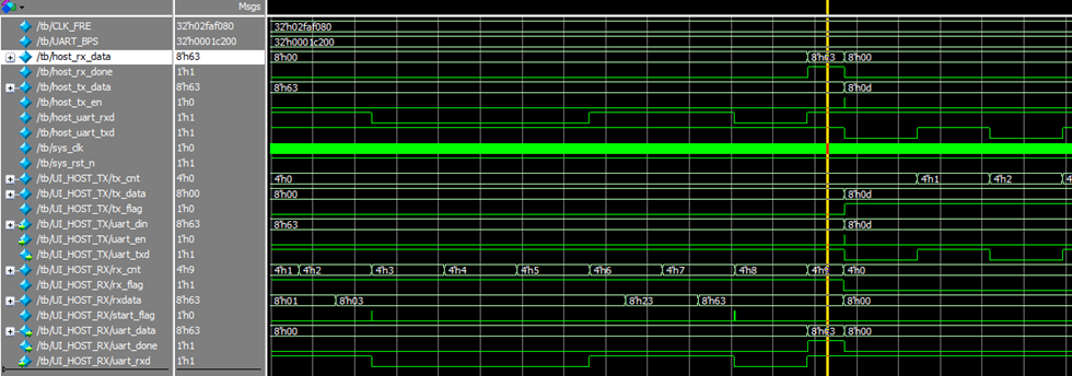
Test and modelsim simulation:
Instantiate the top-level module and the upper computer sending module and receiving module in testbench. The whole loop is simulated to simulate the serial communication between the host computer and FPGA to realize the data loop. Check whether the sending data and receiving data of the upper computer are consistent, and send multiple groups of randomly generated data.
 `timescale 1ns/1ps

module tb();

reg sys_clk = 0;
always #(500.0/50.0) sys_clk = ~sys_clk;

reg sys_rst_n = 0;
initial begin
    #1000
    sys_rst_n = 1;
    #1000
    sys_rst_n = 0;
    #1000
    sys_rst_n = 1;
end

parameter CLK_FRE=50000000;
parameter UART_BPS=115200;

reg         host_tx_en;  //host sent data enable
reg [7:0]   host_tx_data;//host sent data

wire 		host_uart_rxd;//host uart port receive
wire 		host_uart_txd;//host uart port sent

wire         host_rx_done;//host receive finish
wire [7:0]   host_rx_data;//host receive data

uart_top UI_UART_TOP0( // this uart is used to simulate FPGA
    .sys_clk    (sys_clk    ),
    .sys_rst_n  (sys_rst_n  ),

    .uart_rxd   (host_uart_txd  ),
    .uart_txd   (host_uart_rxd  )
    );

uart_send UI_HOST_TX( // here simulate host tx
    .sys_clk    (sys_clk    ),
    .sys_rst_n  (sys_rst_n  ),

    .uart_en	(host_tx_en),
    .uart_din	(host_tx_data),
    .uart_txd   (host_uart_txd)
    );

uart_recv UI_HOST_RX( // here simualte host rx
    .sys_clk    (sys_clk    ),
    .sys_rst_n  (sys_rst_n  ),

    .uart_rxd	(host_uart_rxd),
    .uart_done	(host_rx_done),
    .uart_data  (host_rx_data)
    );

initial begin
    host_tx_en = 0;
    host_tx_data = 0;
    repeat(1000)@(posedge sys_clk);
    repeat(100)begin
        @(posedge sys_clk)begin
            host_tx_en = 1;     //We set the enable signal as a pulse signal in tb, but actually en is connected with done as a level signal
            host_tx_data = $random % 256;//Generates a random number between - 255 and 255
        end
        @(posedge sys_clk)begin // Here, each rising edge generates a random number, and the transmission module is separated by a frame of data:
            host_tx_en = 0;     // Random numbers generate raw data, which will be uart_send lock in
        end                     // Then it is sent out and regenerated into a new random number after sending, which is not generated in each cycle

        wait(host_rx_done);
		wait(~host_rx_done);

    end

end

always @(posedge host_rx_done)
    if (host_tx_data != host_rx_data)begin
        $display("XXXXXXXXXXXXXXXXX");
    end


initial begin
    #1000_000
    $finish;
end

endmodule
You can see the sending random number host_rx_data and received data host_ tx_ The data is consistent, all 8'h63.