1. Continue
config_ht_link in ls3a7a_ setup_ ht_ link. First half of s file:
1.1 first look at the notes of this document
//************************************
// setup_ht_link
// author: chenxk
// date: 2017.11.14
//set up the link between CPU and PCH include two steps:
// 1. config_ht_link(set link parameters) 1. Configured connection parameters
// 2. reset_ht_link(reset to make new configure effect) 2. Restart your connection
//
// for CPU: LS3A2000/LS3A3000
// for PCH: LS7A1000
//************************************
#include "ht.h"
.global config_ht_link
.ent config_ht_link
.set noreorder
.set mips3
//input:
//a0: HT address base(full address base, like: 0x90001e0000000000) base address of ht
//a1: HT bus and hard freq mode related setting:
//[15:12]: 7A freq-0: 200M; 2: 400M; 5: 800M; 9: 1600M; The passed in parameter is 9
//[11: 8]: 3A freq-0: 200M; 2: 400M; 5: 800M; 9: 1600M; The passed in parameter is 9
//[ 7: 4]: GENx-1/3; The passed in parameter is 3
//[ 1]: width-0: 8bit; 1: 16bits; The passed in parameter is 1, 16 bit wide
//[ 0]: reconnect, 0: not reconnect; 1: reconnect} the incoming parameter is 1. Reconnect
//a2: HT soft configure pll setting:
//[63:32]: 7A side ht_pllcfg[31:0] / / the high 32 bits indicate the PLL setting of 7a
//[31: 0]: 3A side ht_pllcfg[31:0] / / the lower 32 bits indicate the PLL setting of 3A
//register usage:
//t0: 3A HT cntl register base address / / t0 indicates the base address of 3A ht controller
//t1: 7A HT cntl register base address / / t1 indicates the base address of 7A ht controller
//t5, t6: tmp variable / / temporary variable
//t2: store a1 / / t2 save the passed in parameter 2
//t3: store a2 / / t2 save the incoming parameter 3
//s1: store ra / / s1 save the return address. It is possible that other functions may be called in the middle
1.2 enter the code and divide it into several paragraphs, which are relatively long.
config_ht_link:

    move    s1, ra    /* The function returns at line 483 */

    dli     t0, 0xfdfb000000    //3A
    dli     t1, 0xfdfe000000    //7A
    daddu   t0, t0, a0          //a0 = 0x90000e0000000000
    daddu   t1, t1, a0
    move    t2, a1
    move    t3, a2

//Some macros in the middle are defined and controlled, and the undefined parts are omitted.

#ifdef  CHECK_HT_PLL_LOCK / / the macro definition is valid
    //check HT PLL lock
    move    t5, $0
    lw      a0, LS3A_HT_PLL_CONF(t0)
    srl     a0, a0, 3
    and     a0, a0, 0x1
    bnez    a0, 2f
    nop
    PRINTSTR("\r\nError: After reconfigure, 3A HT PLL not locked!!!")
    add     t5, t5, 1
2:
#ifdef  CHECK_7A_HT_PLL_LOCK / / the macro definition is valid
    lw      a0, 0x1F4(t1)
    srl     a0, a0, 3
    and     a0, a0, 0x1
    bnez    a0, 2f
    nop
    PRINTSTR("\r\nError: After reconfigure, 7A HT PLL not locked!!!")
    add     t5, t5, 1
2:
#endif
    bnez    t5, 2b
    nop
    TTYDBG("\r\nPLL check success.")    //Execute this sentence
#endif
1.2.1 the first 7 lines of the code.
1) Save ra to s1
2) t0 is the base address of the HT controller of 3A and t1 is the base address of the HT controller of 7A
3) Parameter 2 and parameter 3 are saved to t2 and t3 respectively.
1.2.2 next
1) The register of t5 is cleared$ The value of the 0 register is only 0, which is copied to t5
2) Read the HT register (0x9000,0efd, fb000178) of 3A and judge whether bit [3] is 0. If it is 0, an error occurs, otherwise the jump continues
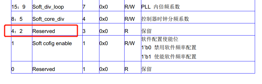
The third position in the document is reserved, and the document is displayed in the document,???? 0x178 is this register. Referring to the register of 7A, the two are a bit similar.
3) read HT register (0x9000,0efd,fb00,01f4) of 7A and judge whether bit [3] is 0. If it is 0, there will be an error, otherwise jump to continue execution
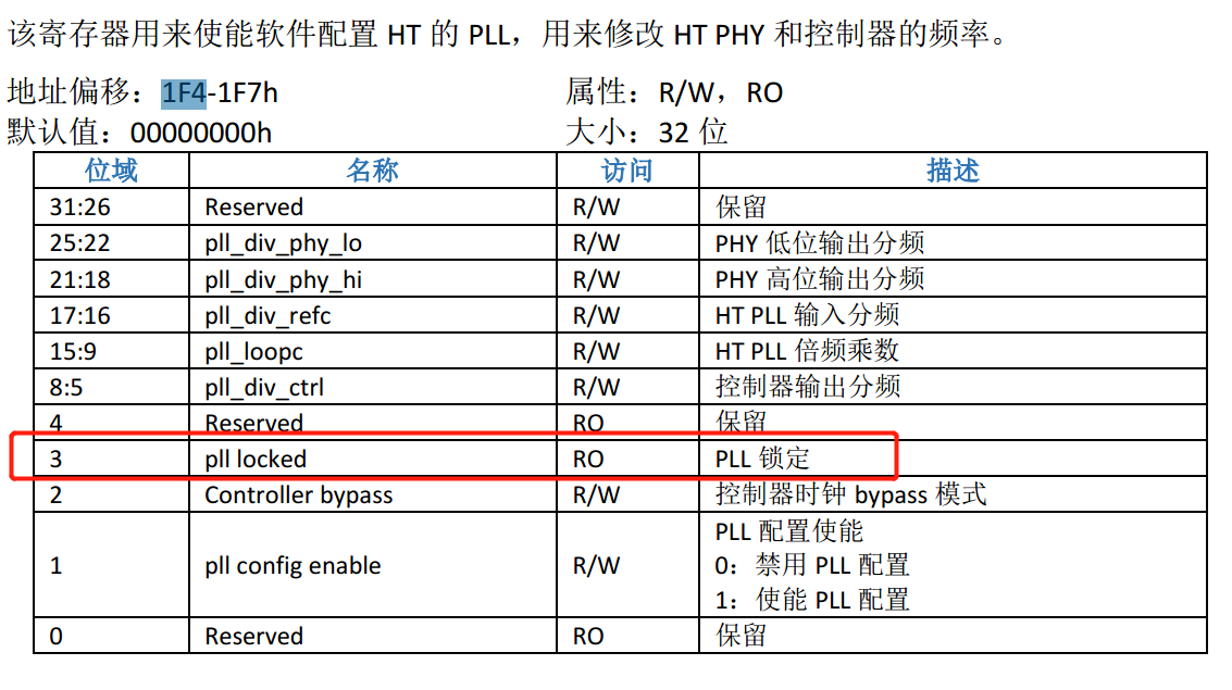
This register is very similar to the partition of the above register. The manual of the last register may be incomplete.
4) if it is not 0, does it mean that the PLL is locked? Well, guess anyway...
1.2.3 next
If t5 is not equal to 0, it means that the just executed error occurs and the loop is dead.
Equal to 0, continue down. Prompt for successful printing
1.3. Continue to look at the code
//wait until HT link up
TTYDBG("\r\nWait HT bus up.")
li t5, 0x1f
1:
lw a0, 0x44(t0)
bal hexserial //Print the value of the register
nop
TTYDBG(">")
addi t5, t5, -1
bnez t5, 2f
nop
TTYDBG("\b\b\b\b\b\b\b\b\b\b\b\b\b\b\b\b\b\b\b\b\b\b\b\b\b\b\b\b\b\b\b=")
li t5, 0x1f
2:
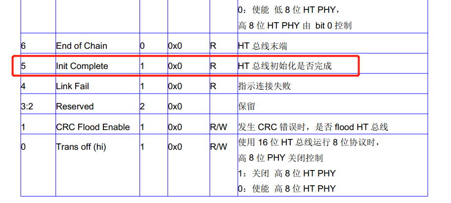
lw a0, 0x44(t0)
li a1, 0x20 //[5] InitComplete is set to 1, indicating that initialization is complete.
and a0, a0, a1 //And operation
beqz a0, 1b //If it is equal to 0, it will jump forward, otherwise continue to execute downward
nop
TTYDBG("\r\n")
lw a0, 0x44(t0)
bal hexserial //Print the value of the register
nop
TTYDBG("\r\n")HT register of 3A (offset address 0x44):
1.4 continue to look at the code
#if HT1_RECONNECT
and a0, t2, 0x1 //t2 the lowest bit is 1
beqz a0, 8f //Line 8f 479, the program ends and returns
nop
TTYDBG("Set 7A side HT:\r\n") //7A1000 manual pdf
TTYDBG("Set width\r\n")
lw a0, 0x44(t1)
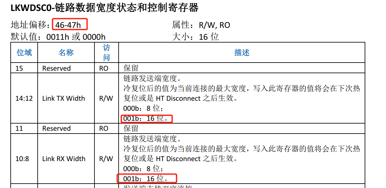
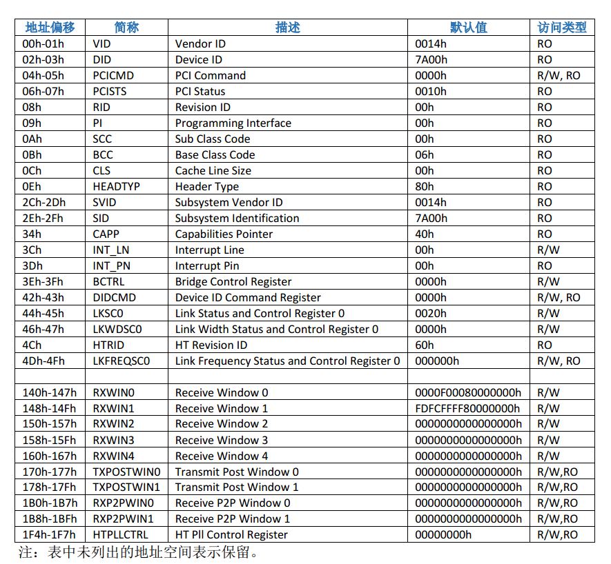
li a1, (0xff<<24) //Note the value of the 46-47H register in the document
not a1, a1 //a1 = 00ff,ffff
and a0, a0, a1 //[31:24] cleared
li a1, HT_WIDTH_CTRL_8 //a1 = 0
srl t5, t2, 1 //t5 = t2 >> 1
and t5, t5, 0x1 //t2[1] = 1
beqz t5, 1f //Not equal to 0, no jump
nop
li a1, HT_WIDTH_CTRL_16 //a1 = 0x11
1:
sll a1, a1, 24 //a1 = 0x1100,0000
or a0, a0, a1 //[28] [24] of a0 is set to 1, and 16 bit width settings are set at the transmitting end and receiving end
sw a0, 0x44(t1) //Write register
lw a0, 0x44(t1) //Information printing,
bal hexserial
nop
TTYDBG("\r\n")
TTYDBG("Set Freq\r\n")
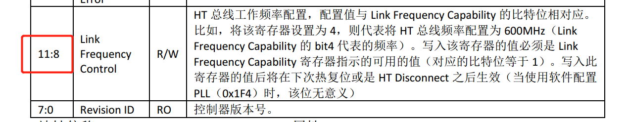
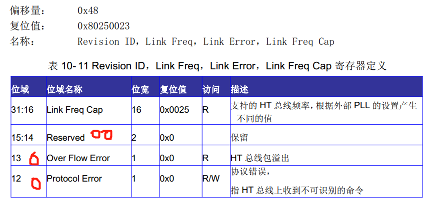
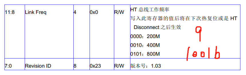
lw a0, 0x4c(t1) //Link frequency configuration register, only 8-11 bits can be written
li a1, (0xf<<8)
not a1, a1 //a1 = 0xffff,f0ff
and a0, a0, a1 //[11:8] reset
srl a1, t2, 12 //Shift right 12 bits
and a1, a1, 0xf //The remaining 9 HT bus operating frequency configurations
sll a1, a1, 8 //Shift left 8 bits
or a0, a0, a1 //9 write to [11:8]
sw a0, 0x4c(t1) //Register Offset 4c
lw a0, 0x4c(t1) //Print out [11:8] = 0; Print value: 0x82250060
bal hexserial
nop
TTYDBG("\r\n")
TTYDBG("Set soft config\r\n")
dsrl a1, t3, 32 //Move 32 bits to the right and take the higher 32 bits
sw a1, 0x1F4(t1)
lw a0, 0x1F4(t1) //HT PLL control register to configure the clock frequency.
bal hexserial
nop
TTYDBG("\r\n")
srl a1, t2, 4 //Shift right 4
and a1, a1, 0xf
li a0, 3
bne a0, a1, 4f //Equal, no jump
nop
TTYDBG("Set Gen3 mode\r\n")
lw a0, 0x6c(t1) //
li a1, (0xff<<16)
not a1, a1 //a1 = 0xff00,ffff
and a0, a0, a1 //Reset [23:16]
li a1, (0x60<<16)
or a0, a0, a1 //[23:16]= 0x60
sw a0, 0x6c(t1) //Document description not found!!!!!!!
lw a0, 0x6c(t1)
bal hexserial
nop
TTYDBG("\r\n")
TTYDBG("Set retry mode\r\n")
lw a0, 0x64(t1)
li a1, (0xc1<<0)
not a1, a1
and a0, a0, a1 //Reset [7:6], [0]
li a1, (0x81<<0)
or a0, a0, a1
sw a0, 0x64(t1) //Document description not found!!!!!!!
lw a0, 0x64(t1)
bal hexserial
nop
TTYDBG("\r\n")
TTYDBG("Enable scrambling\r\n")
lw a0, 0xd0(t1)
li a1, (0x78<<0)
not a1, a1
and a0, a0, a1 //Reset [6:4], [3]
li a1, (0x78<<0)
or a0, a0, a1 //[6:4] = 7 [3] = 1
sw a0, 0xd0(t1)
lw a0, 0xd0(t1)
bal hexserial
nop
TTYDBG("\r\n")
4:
TTYDBG("set buffer num\r\n")
lw a0, 0x1dc(t1)
li a1, 0xfffffff
or a0, a0, a1
sw a0, 0x1dc(t1)
lw a0, 0x1dc(t1)
bal hexserial
nop
TTYDBG("\r\n")
//Set CPU side HT
TTYDBG("Set CPU side HT:\r\n") //Execution, 3A documentation section.
//HT bus width
TTYDBG("Set width\r\n")
li a1, HT_WIDTH_CTRL_8
srl t5, t2, 1
and t5, t5, 0x1
beqz t5, 1f //Jump when it is equal to 0, but it does not actually jump
nop
li a1, HT_WIDTH_CTRL_16 //0x11
1:
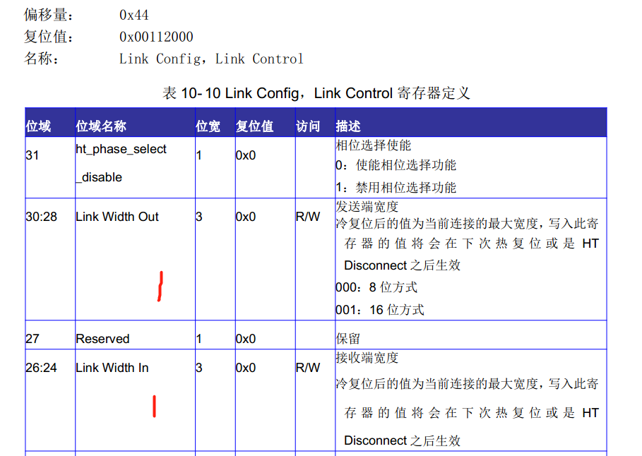
sb a1, 0x47(t0) //0x44 [31:24] high 8 bits, enable phase selection, receive and send 16 bit mode
lw a0, 0x44(t0) //Information printing
bal hexserial
nop
TTYDBG("\r\n")
//Set HT bus frequency
TTYDBG("Set Freq\r\n")
srl a1, t2, 8 //9
and a1, a1, 0xf //a1= 9
sb a1, (LS3A_HT_FREQ+1)(t0) //0x4d this byte [11:8] = 9 has ambiguous meaning in the document
lw a0, LS3A_HT_FREQ (t0) //0x4c, information printing
bal hexserial
nop
TTYDBG("\r\n")
TTYDBG("Set soft config\r\n")
move a1, t3
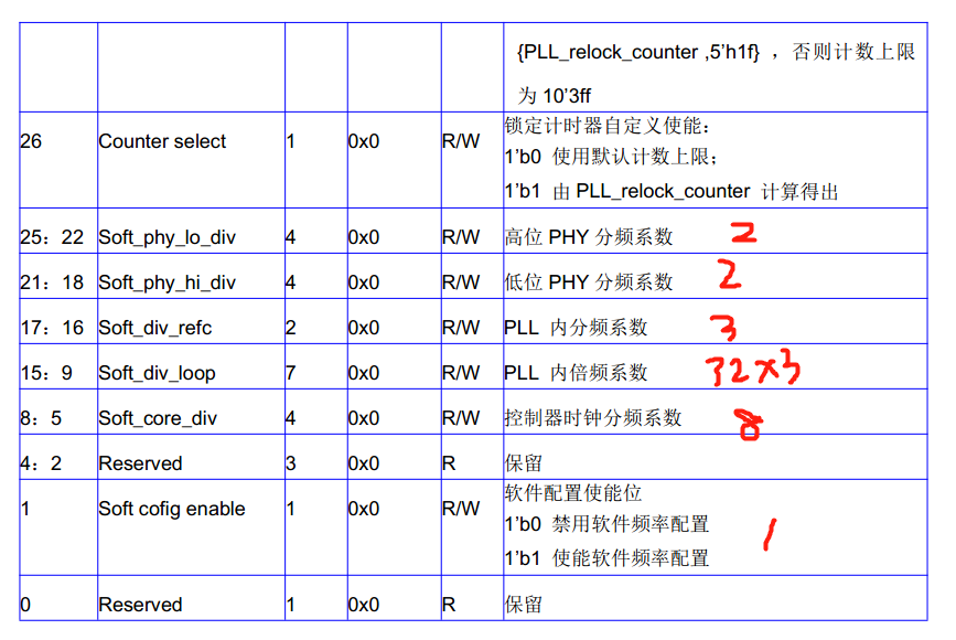
sw a1, LS3A_HT_PLL_CONF(t0) //0x178100 page, software frequency configuration
lw a0, LS3A_HT_PLL_CONF(t0) //Information printing
bal hexserial
nop
TTYDBG("\r\n")
srl a1, t2, 4 //Logical shift right
and a1, a1, 0xf //3
li a0, 3
bne a0, a1, 4f //Equal, no jump
nop
TTYDBG("Set GEN3 mode\r\n")
li a1, 0x88600000
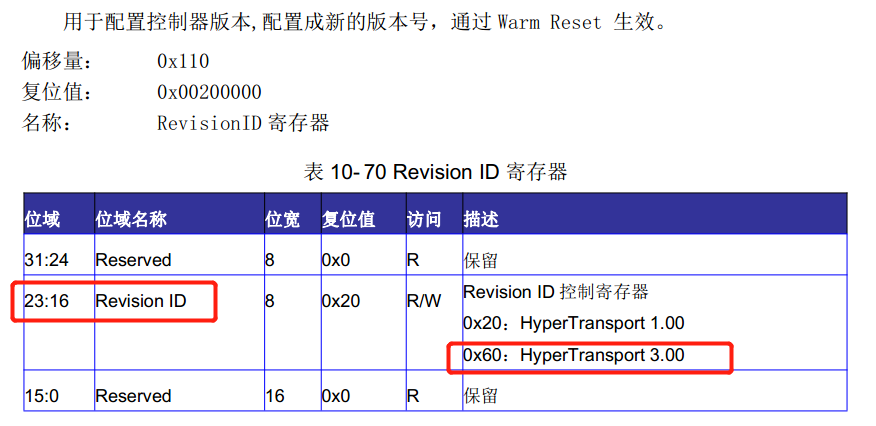
sw a1, LS3A_HT_REVISION(t0) //0x110 [23:16] = 0x60 indicates HT3 0 other bits read only
lw a0, LS3A_HT_REVISION(t0) //Information printing
bal hexserial
nop
TTYDBG("\r\n")
TTYDBG("Set retry mode\r\n")
li a1, 0x81
sb a1, LS3A_HT_RETRY_CONTROL(t0) //0x118 error retransmission enable [7:6] = 2, running retransmission times, [0] may be the enable bit, which is not given in the document
lw a0, LS3A_HT_RETRY_CONTROL(t0) //Information printing
bal hexserial
nop
TTYDBG("\r\n")
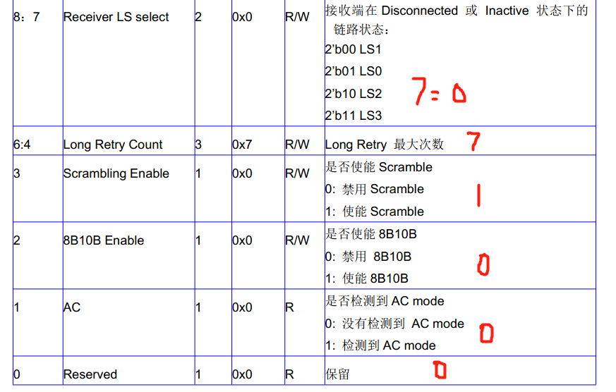
TTYDBG("Enable scrambling\r\n")
li a1, 0x78
sb a1, LS3A_HT_LINK_TRAIN(t0) //0x130 document 97 pages. Note the meaning of the lower 8 bits 01111000 set to enable scrambling
lw a0, LS3A_HT_LINK_TRAIN(t0) //Information printing, function ready to return, 482 lines
bal hexserial
nop
TTYDBG("\r\n")
4:
//Some code without macro definition is deleted in the middle
8:
#endif
move ra, s1 /* Function return */
jr ra
nop1.4.1 t2(t2 = 9<<12 | 9<<8 | 3<<4 | 1<<1 | 1<<0;) Is the saved parameter passed in. The lowest order is 1. It does not end. Continue execution
1.4.2} before "TTYDBG("Set Freq\r\n ")", the high 31-24 bits (which should be 0x47 address) of the 0x44-0x47 register on 7A side are cleared, [28] and [24] are set to 1, and other bits remain unchanged
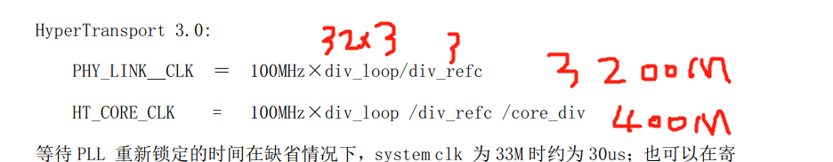
1.4.3} before "TTYDBG("Set soft config\r\n ")" code, configure 0x4c register and set bit [11-8] to 91600MHz
1.4.4 the next 7 sentences, until the end of carriage return line feed.
Set the HTPLL register value of 7A to 2 < < 22 | 2 < < 18 | 2 < < 16 | 32 * 2 < < 9 | 8 < < 5 | 1 < < 1;
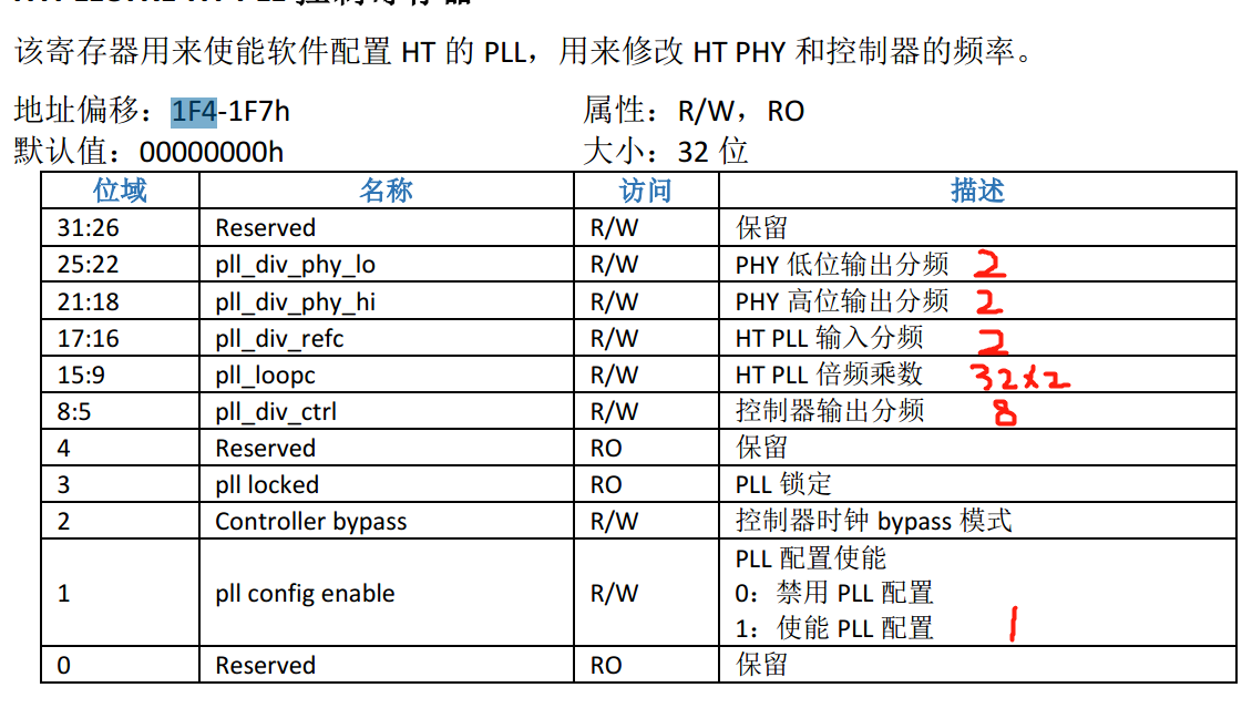
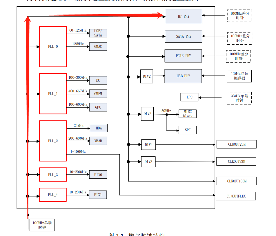
I don't know where the formula is? Looking at the figure below, it seems that HT PHY generates its own clock, which has nothing to do with the five PLL s????
1.4.5 before the "TTYDBG("Set retry mode\r\n ")" code, this comment indicates the configuration of gen3 0, but the register of 0x6c did not find the document description!!
Skip it, you can't guess it!!!!
1.4.6 before the "TTYDBG("Enable scrambling\r\n ")" code, the document description was not found in the register of 0x64!!
Skip it, you can't guess it!!!!
1.4.7 before the "TTYDBG("set buffer num\r\n ")" code, the document description was not found in the register of 0xd0!!
Skip it, you can't guess it!!!!
Description of "db1.dc!" not found before "db1.dc!" \ R \ n!!
Skip it, you can't guess it!!!!
1.5 intercept the code of cpu HT (the same as the latter half of 1.4)
    //Set CPU side HT
    TTYDBG("Set CPU side HT:\r\n")     //Execution, 3A documentation section.
    //HT bus width
    TTYDBG("Set width\r\n")
    li      a1, HT_WIDTH_CTRL_8
    srl     t5, t2, 1
    and     t5, t5, 0x1
    beqz    t5, 1f             //Jump when it is equal to 0, but it does not actually jump
    nop
    li      a1, HT_WIDTH_CTRL_16  //0x11
1:
    sb      a1, 0x47(t0)    //0x44 [31:24] high 8 bits, enable phase selection, receive and send 16 bit mode
    lw      a0, 0x44(t0)    //Information printing
    bal     hexserial
    nop
    TTYDBG("\r\n")

    //Set HT bus frequency
    TTYDBG("Set Freq\r\n")
    srl     a1, t2, 8           //9
    and     a1, a1, 0xf         //a1= 9
    sb      a1, (LS3A_HT_FREQ+1)(t0)   //0x49 this byte [11:8] = 9 has ambiguous meaning in the document
    lw      a0,  LS3A_HT_FREQ   (t0)   //0x48, information printing

    bal     hexserial
    nop
    TTYDBG("\r\n")

    TTYDBG("Set soft config\r\n")
    move    a1, t3
    sw      a1, LS3A_HT_PLL_CONF(t0)   //0x178100 page, software frequency configuration
    lw      a0, LS3A_HT_PLL_CONF(t0)   //Information printing
    bal     hexserial
    nop
    TTYDBG("\r\n")

    srl     a1, t2, 4          //Logical shift right
    and     a1, a1, 0xf        //3
    li      a0, 3
    bne     a0, a1, 4f         //Equal, no jump
    nop
    TTYDBG("Set GEN3 mode\r\n")
    li      a1, 0x88600000
    sw      a1, LS3A_HT_REVISION(t0)   //0x110 [23:16] = 0x60 indicates HT3 0 other bits read only
    lw      a0, LS3A_HT_REVISION(t0)   //Information printing
    bal     hexserial
    nop
    TTYDBG("\r\n")

    TTYDBG("Set retry mode\r\n")
    li      a1, 0x81
    sb      a1, LS3A_HT_RETRY_CONTROL(t0)   //0x118 error retransmission enable [7:6] = 2, running retransmission times, [0] may be the enable bit, which is not given in the document
    lw      a0, LS3A_HT_RETRY_CONTROL(t0)   //Information printing
    bal     hexserial
    nop
    TTYDBG("\r\n")

    TTYDBG("Enable scrambling\r\n")
    li      a1, 0x78
    sb      a1, LS3A_HT_LINK_TRAIN(t0)   //0x130 document 97 pages. Note the meaning of the lower 8 bits 01111000 set to enable scrambling
    lw      a0, LS3A_HT_LINK_TRAIN(t0)    //Information printing, function ready to return, 482 lines
    bal     hexserial
    nop
    TTYDBG("\r\n")
1.5.1 , a1 = 0x11 in the previous sentences
1.5.2 then assign 0x47 byte 0x11 (i.e. [31-24] of 0x44) and set the width to 16 bits.
1.5.3 perform byte operation on 0x49 register and write the number 9
1.5.4 to 7 statements starting with "TTYDBG("Set soft config\r\n ")", register 0x178
Set PLL frequency of HT
How do you think it's not 1600M????
1.5.5 configure 0x110 register
1.5.6 configure 0x118 register as 0x81, and the document description is incomplete!!

1.5.7 configure 0x130 register as 0x78, and only [7-0] bits are valid
Then the function returns.
2. Summary:
1. This part mainly refers to the clock configuration of HT, 1600MHz, 16bits mode and HT3 0, enable scrambling, and the maximum number of retries is 2
2. The configuration does not take effect immediately. You have to restart the HT controller, which is the next step.
3. The description of the document is really not detailed. You may need to read it together with the documents of 3A and 7A. Guess by the way. Alas....