In the next few articles, we will briefly explore the internal principle of the algorithm of multiple layer mixing modes in PS. after all, there is no official data in this regard, so many aspects are only my own exploration and practice, which may be quite different from the actual situation.
In the practice of PS, the existence of layer style makes it possible to transform a simple graphic into a rich style. In various versions of PS, the options of layer style are more and more rich and the functions are more and more powerful. As a successful graphics and graphics editing software, whether the layer style function is missing can also be regarded as a typical sign of its strong vitality. For example, GIMP, as the shoulder of the image open source community, does not have this function. The commercial software we can see usually also rarely has this function.
In the CS6 version of PS I use, 10 layer styles such as bevel and relief, stroke, inner shadow, inner glow, gloss, color overlay, gradient overlay, pattern overlay, outer glow and projection are provided. In my subsequent articles, I will describe the principle and implementation of other 8 styles except outer glow and inner glow.
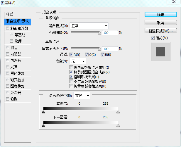
This paper will briefly describe the principle of projection style. The controllable parameter interface of projection style is as follows:
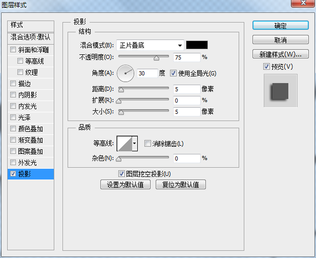
Parameters include blending mode, opacity, angle, distance, extension, size 'contour, anti aliasing, noise, etc. Let's start with the general direction.
In PS, if we open a JPG image (usually in RGB format), we will find that PS is the image, its name is the background layer, and there is a lock symbol on the right side of the layer, as shown below:
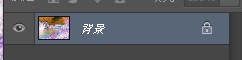
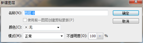
If we double-click this layer at this time, the interface of creating a new layer will appear, rather than the rotation direction of the layer style, as shown in the above figure.
However, if we open a 32-bit PNG image with transparent channel, the system names the image with layer 0 by default, and there is no lock symbol on the back.
Double click the layer symbol to open the layer style dialog box.
Through this phenomenon, we can make a simple guess. The layer style needs Alpha channel, and the actual research also shows that most layer styles (except color overlay, gradient overlay and pattern overlay, our bureau should expel them from the style) are processed for the data of Alpha channel, and then combined with a certain color and the original image to a certain extent.
Perfect can even follow another popular saying. The layer style actually virtualizes one or more layers according to certain rules, and then mixes them with the original image through different layer positions (at the top or bottom), mixing style, opacity, etc. This is also the source of the concept of mixing mode and opacity in all styles.
Go back to this projection style again. Get this effect at will in PS, and you can intuitively feel that the function of this style is to create a shadow layer under the current layer according to the selected parameters.
Then the core idea of my implementation is as follows:
Step 1: offset the Alpha information of the original drawing by a certain angle according to the specified angle, and set the invalid area Alpha to 0 after offset.

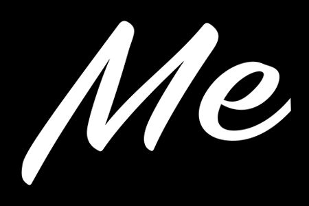
Original image the Alpha channel information of the original image deviates from the specified angle (angle 30, distance 20)
The simple code is as follows:
    float SinV = -sinf(Angle / 180.0 * 3.1415926f);
    float CosV = cosf(Angle / 180.0 * 3.1415926f);
    int Left = (int)(Distance * CosV + 0.499999f);
    int Top = (int)(Distance * SinV + 0.499999f);
    //    Calculates the offset information for the Alpha channel
    for (int Y = 0; Y < Height; Y++)
    {
        int NewY = Y + Top;
        if ((NewY < 0) || (NewY >= Height))
        {
            memset(ShiftA + Y * Width, 0, Width);
        }
        else
        {
            unsigned char *LinePD = ShiftA + Y * Width;
            for (int X = 0; X < Width; X++)
            {
                int NewX = X + Left;
                if ((NewX < 0) || (NewX >= Width))
                {
                    LinePD[X] = 0;
                }
                else
                {
                    int Index = NewY * Stride + NewX * 4 + 3;
                    LinePD[X] = Src[Index];
                }
            }
        }
    }
The angle and distance in the interface jointly determine the deviation degree of this Alpha channel.
For the following size and expansion parameters, combined with some references in the network, through my practice, we can basically determine the following algorithm.
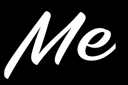
First, we set the size to 10, and then set the extension to 100%. For the above figure, the following effects can be achieved:


The result when the size is 10, the result when the expansion is 100%, and the result when the size is 0
It can be seen that when the size is 10 and the expansion is 100%, the shadow part becomes thicker. Through the test, we find that this should actually be a circular maximum algorithm for the Alpha selected area after the above offset. We are circular. We can compare the results of the maximum values of circles and rectangles with the same radius:


Maximum value of rectangle with radius of 10 maximum value of circle with radius of 10
Obviously, it can be seen that the rectangle can not retain the original smooth fillet, but the circle can.
Therefore, we speculate that expansion is a circular maximum algorithm for the selected area, and the radius of the maximum value is related to the size and the expanded data. According to the% percentage behind the PS interface expansion, it can be identified as the percentage of the size.
As for the size parameter, it is obvious that as the size increases, the shadow becomes more and more blurred. Therefore, it can be guessed that this is to blur Alpha. However, in my test, it seems that it is not Gaussian blur. I don't know what kind of blur it is actually.
    //    The second step is to block down the Alpha, which is the circular maximum algorithm
    int ChokeSize = (Size * Choke + 49) / 100;
    if (ChokeSize != 0)                //    Blocking and suffocating
    {
        Status = IM_MaxFilter_Round_Gray(ShiftA, ShiftA, Width, Height, Width, ChokeSize);
        if (Status != IM_STATUS_OK)    goto FreeMemory;
    }
    //    The third step is to feather Alpha, Gaussian blur (but PS doesn't know what kind of blur it belongs to)
    if ((Size != 0) && (Size != ChokeSize))
    {
        Status = IM_GaussBlur(ShiftA, ShiftA, Width, Height, Width, Size - ChokeSize);
        if (Status != IM_STATUS_OK)    goto FreeMemory;
    }
Well, there is another key thing below, that is, the contour line, which is amazing on the Internet. All the great gods have made comments. In my opinion, they are all false gods. That thing is actually what he shows on the surface, which is a curve adjustment, and it also means the same as the curve of PS itself, but what he adjusts is not the RGB in the image, but the Alpha here. Different results are obtained by dynamically adjusting this Alpha.
    //    The fourth step is the contour algorithm for the selected area, which is actually a look-up table
    for (int Y = 0; Y < Height * Width; Y++)
    {
        ShiftA[Y] = Table[ShiftA[Y]];
    }
Then the last step is to create a new layer according to the opacity, mixing mode and the background color provided by the user. This layer is located below the current layer for layer mixing. If it is a separate layer, because there are no other layers under this layer, the mixing style does not work here (except for the alternative dissolution). At this time, a simple mixing code is as follows:
    for (int Y = 0; Y < Height; Y++)
    {
        unsigned char *LinePD = Dest + Y * Stride;
        unsigned char *LinePS = Src + Y * Stride;
        unsigned char *LinePA = ShiftA + Y * Width;
        for (int X = 0; X < Width; X++)
        {
            int B1 = BackColor_B, G1 = BackColor_G, R1 = BackColor_R, A1 = LinePA[X];
            int B2 = LinePS[0], G2 = LinePS[1], R2 = LinePS[2], A2 = LinePS[3];
            int NewA1 = A1 * Opacity;
            int BlendAlpha = IM_Div255(A2 * NewA1);
            int Alpha = A2 * 255 + NewA1 - BlendAlpha;
            if (Alpha != 0)
            {
                LinePD[0] = (B1 * NewA1 + B2 * A2 * 255 - BlendAlpha * B1) / Alpha;
                LinePD[1] = (G1 * NewA1 + G2 * A2 * 255 - BlendAlpha * G1) / Alpha;
                LinePD[2] = (R1 * NewA1 + R2 * A2 * 255 - BlendAlpha * R1) / Alpha;
            }
            else
            {
                LinePD[0] = LinePS[0];
                LinePD[1] = LinePS[1];
                LinePD[2] = LinePS[2];
            }
            LinePD[3] = IM_Div255(Alpha);
            LinePS += 4;
            LinePD += 4;
        }
    }
Note that the mixed Alpha here needs to be changed.
As for the anti aliasing in the interface, it should be aimed at the curve. This is to add anti aliasing function during curve interpolation. It doesn't matter what kind of noise, that is, add some random noise to the Alpha information. It's not that hard.
Of course, after some other tests, it is found that the projection in PS has some more complex logic, which is inconsistent with the description of this paper, but the effect of this paper can partially restore the results to a certain extent, which is enough to complete the task for some ordinary applications
Provide a link worker test: https://files.cnblogs.com/files/Imageshop/DropShadow.rar