preface
You can't play electronics without an oscilloscope, and you can't go whoring with a school oscilloscope after graduation. As the saying goes: no conditions create conditions. If there is no oscilloscope, create an oscilloscope. It sounds tall, but it's not difficult. There are many open source oscilloscopes on the Internet, the most representative of which is Lao Liu oscilloscope . Although the circuit is simple and powerful, and the party is too lazy to do it, it also has a great threshold. It doesn't want to weld, draw PCB, or pick various components. It wants a simple and practical oscilloscope with low cost, rapid implementation and convenient expansion. If you don't bother to find it, you'd better make your own wheels.
Tip: this project only uses a treasure finished product CH32F103C8T6 development board. The hardware is simple. You can add software and hardware functions according to your needs.
1, Look at the results first
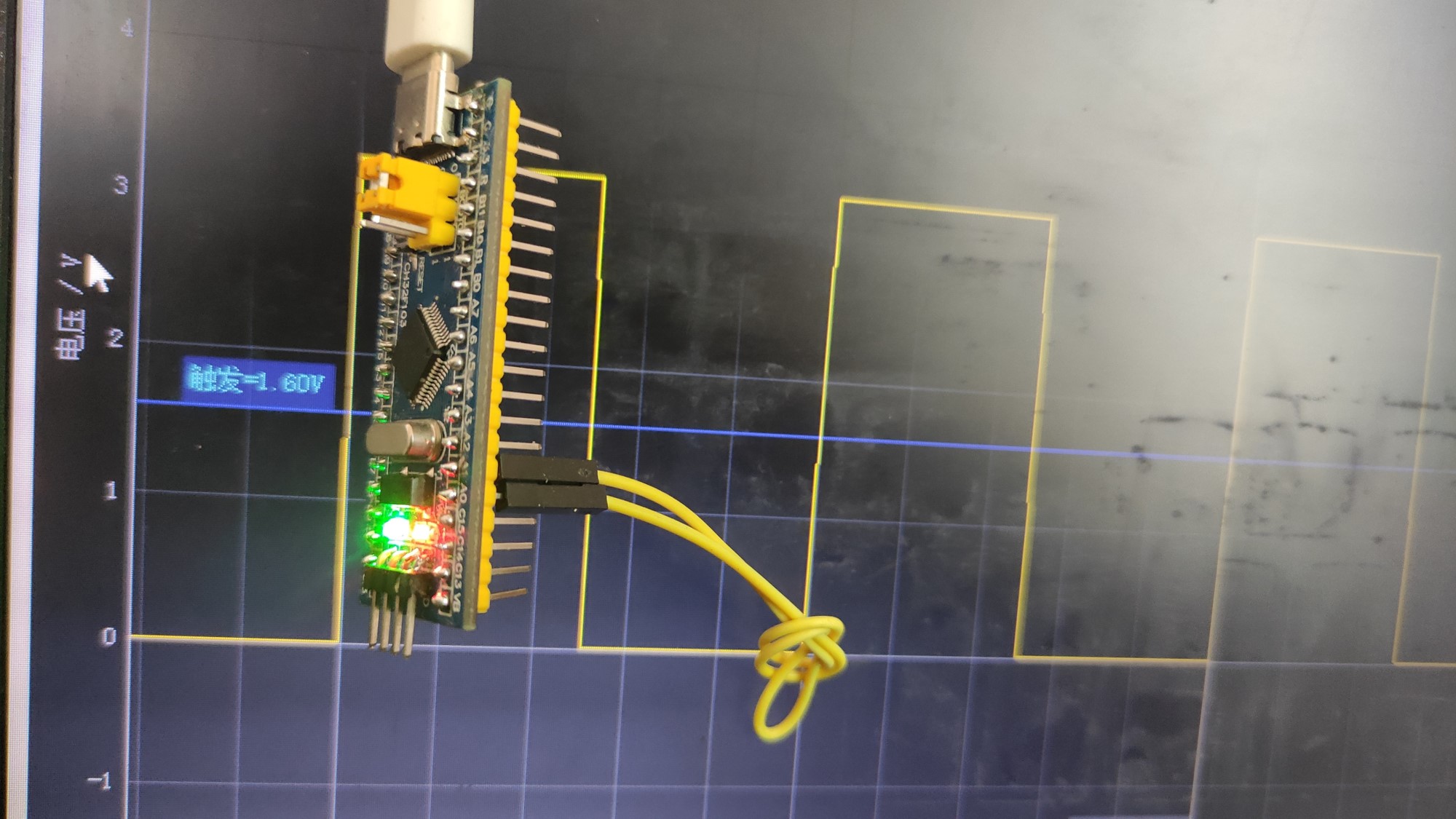
Note: A1 pin is the signal input pin, and A0 outputs 1KHz square wave signal for correction. It has the following functions and characteristics:
- A0 port has 3.3V 1KHz basic square wave output for calibration.
- The signal measurement range of A1 signal input port is 0~3.3V.
- 32 MCU supports 1M sampling rate at most, but when the system clock is 72M, it supports 857.1k sampling rate at most (related to ADC clock frequency division coefficient). In accordance with Nyquist sampling law, the sampling accuracy is 12 bits.
- The upper computer is developed in Python, compatible with Linux and Windows systems, and communicates through the USB virtual serial port of 32 single chip microcomputer.
- The maximum cache of USB virtual serial communication packet is 1200 bytes, so the number of single sampling points is limited to 512 in the program (one sampling point accounts for two bytes).
- It has basic measurement functions: measuring frequency, pulse width and duty cycle (self reading).
- Only automatic rising edge trigger function.
- add to Bessel interpolation function
- Project open source https://github.com/ClassmateXie/32Oscilloscopes
2, Use steps
1 run the software
1.1 Windows users directly run the packaged software
CH32 oscilloscope exe
1.2 install Python environment operation source code (pit entry)
Enter CH32 oscilloscope py file directory, right-click to open the terminal
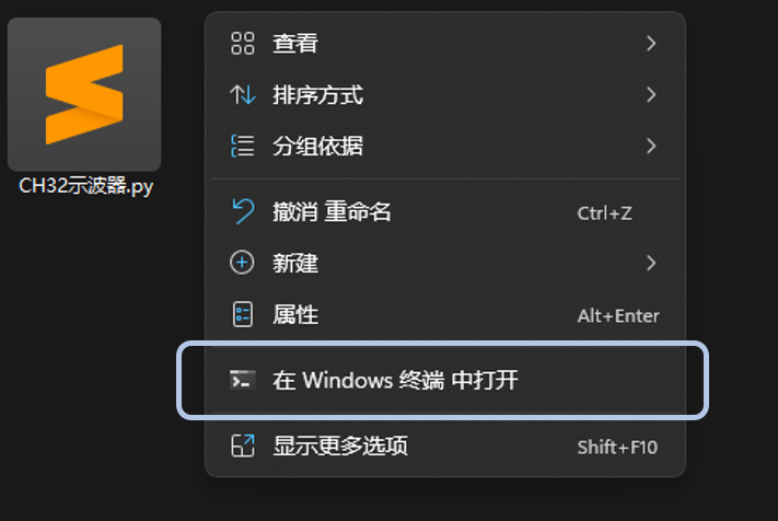
Enter the command line
python .\CH32 Oscilloscope.py
If an error is reported, install the corresponding python library according to the prompt, for example:
pip install pyqtgraph
pip install numpy
pip install pyserial
pip install PyQt5
pip install scipy
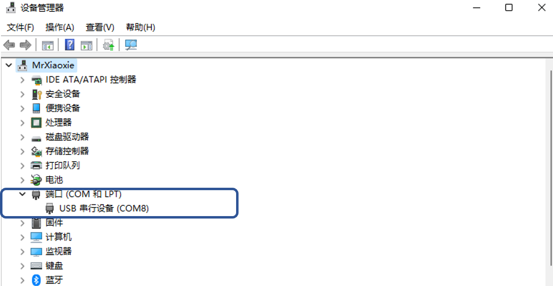
2 select port
The initial interface is as follows:
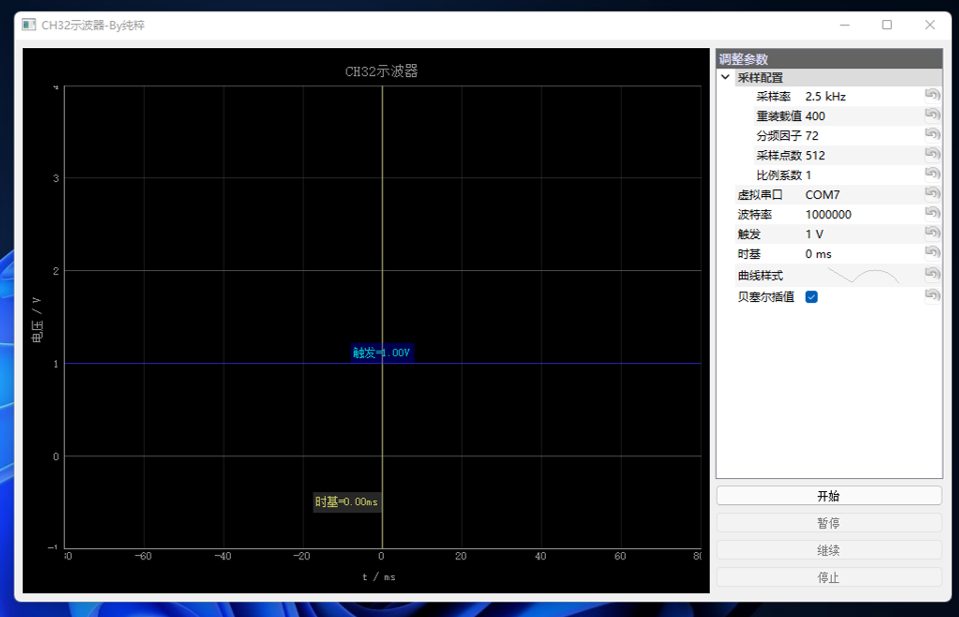
Modify the virtual serial port to the corresponding port (viewed in the device manager, the default is COM7), and the communication baud rate is 1000000 by default
3, Source code analysis
Most of the time in the development process of the project is to consolidate the basic knowledge. Although the overall difficulty of the project is small, we have a deeper understanding of the functions of ADC, DMA, TIM, NVIC and USB of 32 single chip microcomputer in the development process. The development process is hereby recorded.
1. Overall flow chart of procedure
1.1 USB serial port interrupt service function
1.2 ADC sampling process
1.3 DMA transmission process
2 lower computer source code
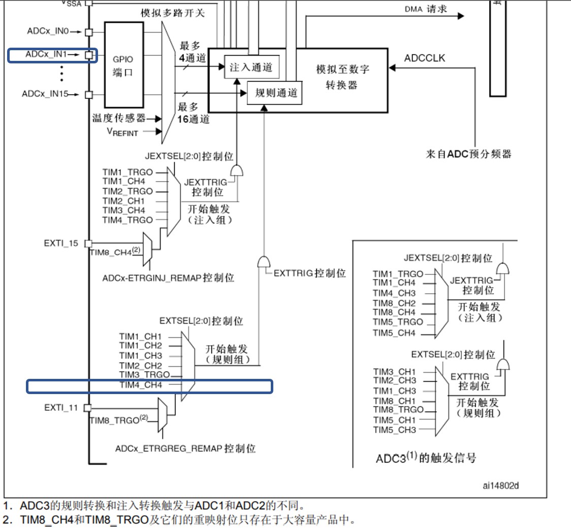
2.1 TIM configuration function
Configure the frequency of PWM generated by TIM4 channel 4 as the trigger source of ADC rule group
/*******************************************************************************
* Function name: TIM_ReSet
* Function function 		   :  TIM restart
* Input: Period reload value, Prescaler frequency division factor
* Output: None
*******************************************************************************/
void TIM_ReSet(u16 Period,u16 Prescaler)
{
	static TIM_TimeBaseInitTypeDef TIM_TimeBaseStructure;
	static TIM_OCInitTypeDef TIM_OCInitStructure;
	TIM_TimeBaseStructure.TIM_Period = Period-1; //Set TIM2 comparison cycle
	TIM_TimeBaseStructure.TIM_Prescaler = Prescaler-1;//The main frequency of the system is 72M, which is divided here
	TIM_TimeBaseStructure.TIM_ClockDivision = 0x0;
	TIM_TimeBaseStructure.TIM_CounterMode = TIM_CounterMode_Up;
	TIM_TimeBaseInit(TIM4, &TIM_TimeBaseStructure);
	TIM_OCInitStructure.TIM_OCMode = TIM_OCMode_PWM1;//Detailed description below
	TIM_OCInitStructure.TIM_OutputState = TIM_OutputState_Enable;//TIM_OutputState_Disable;
	TIM_OCInitStructure.TIM_Pulse = Period>>1;
	TIM_OCInitStructure.TIM_OCPolarity = TIM_OCPolarity_Low;//If PWM1 is Low, PWM2 is High
	TIM_OC4Init(TIM4, &TIM_OCInitStructure);
	TIM_Cmd(TIM4, ENABLE);
}
2.2 DMA configuration function
u16 buf_len = 512; //USB send cache Max 1200 bytes, buf_len must be less than 600
u16 ADC_Buf[512]={0};
/*******************************************************************************
* Function name: DMA_ReSet
* Function function 		   :  DMA restart
* Input: len transmission data volume
* Output: None
*******************************************************************************/
void DMA_ReSet(u16 len)
{
	static DMA_InitTypeDef DMA_InitStructure;
	buf_len = len;
	//========DMA configuration=============/
	DMA_ClearFlag(DMA1_FLAG_TC1);
	DMA_InitStructure.DMA_PeripheralBaseAddr = (u32)&ADC1->DR;//ADC address
	DMA_InitStructure.DMA_MemoryBaseAddr = (uint32_t)ADC_Buf; //Memory address
	DMA_InitStructure.DMA_DIR = DMA_DIR_PeripheralSRC; //Direction (from peripheral to memory)
	DMA_InitStructure.DMA_BufferSize = len; //Size of transmitted content
	DMA_InitStructure.DMA_PeripheralInc = DMA_PeripheralInc_Disable; //Fixed peripheral address
	DMA_InitStructure.DMA_MemoryInc = DMA_MemoryInc_Enable; //Memory address increment
	DMA_InitStructure.DMA_PeripheralDataSize = DMA_PeripheralDataSize_HalfWord ; //Peripheral data unit
	DMA_InitStructure.DMA_MemoryDataSize = DMA_MemoryDataSize_HalfWord ;    //Memory data unit
	DMA_InitStructure.DMA_Mode = DMA_Mode_Normal; //DMA mode: single transmission
	DMA_InitStructure.DMA_Priority = DMA_Priority_High ; //Priority: high
	DMA_InitStructure.DMA_M2M = DMA_M2M_Disable;   //Disable memory to memory transfer
	DMA_Init(DMA1_Channel1, &DMA_InitStructure);  //Configure channel 1 of DMA1
	DMA_Cmd(DMA1_Channel1,ENABLE);
}
2.3 ADC configuration function
void ADC1_CH1_Init(void)
{
	GPIO_InitTypeDef GPIO_InitStructure; //Define structure variables
	ADC_InitTypeDef  ADC_InitStructure;
	NVIC_InitTypeDef NVIC_InitStructure;
  	/* Configure one bit for preemption priority */
  	NVIC_PriorityGroupConfig(NVIC_PriorityGroup_1);
	RCC_AHBPeriphClockCmd(RCC_AHBPeriph_DMA1,ENABLE);
	RCC_APB2PeriphClockCmd(RCC_APB2Periph_GPIOA|RCC_APB2Periph_ADC1,ENABLE);
	RCC_APB1PeriphClockCmd(RCC_APB1Periph_TIM4,ENABLE);//Enable TIM4 clock
	RCC_ADCCLKConfig(RCC_PCLK2_Div6);//Set ADC frequency division factor 6 72m / 6 = 12, and the maximum ADC time cannot exceed 14M
	//==========Port settings====================//
	GPIO_InitStructure.GPIO_Pin=GPIO_Pin_1;//ADC
	GPIO_InitStructure.GPIO_Mode=GPIO_Mode_AIN;	//Analog input
	GPIO_InitStructure.GPIO_Speed=GPIO_Speed_50MHz;
	GPIO_Init(GPIOA,&GPIO_InitStructure);
	//==========ADC configuration====================//
	ADC_InitStructure.ADC_Mode = ADC_Mode_Independent;
	ADC_InitStructure.ADC_ScanConvMode = DISABLE;//Non scanning mode
	ADC_InitStructure.ADC_ContinuousConvMode = DISABLE;//Turn off continuous conversion
	ADC_InitStructure.ADC_ExternalTrigConv = ADC_ExternalTrigConv_T4_CC4;//Timer 4 Channel 4 trigger detection
	ADC_InitStructure.ADC_DataAlign = ADC_DataAlign_Right;//Right align
	ADC_InitStructure.ADC_NbrOfChannel = 1;//One transformation is in the rule sequence, that is, only rule sequence 1 is transformed
	ADC_Init(ADC1, &ADC_InitStructure);//ADC initialization

	ADC_DMACmd(ADC1, ENABLE);//Enable ADC1 module DMA

	//=========Timer configuration==============//
//	TIM_ReSet(100,72);//10K sampling rate
	//========DMA configuration=============/
	DMA_DeInit(DMA1_Channel1);
	DMA_ITConfig(DMA1_Channel1,DMA_IT_TC,ENABLE);//Enable DMA transfer completion interrupt
//	DMA_DeInit(DMA1_Channel1);
//	DMA_ReSet(buf_len);
//	DMA_ITConfig(DMA1_Channel1,DMA_IT_HT,ENABLE);
//	DMA_ITConfig(DMA1_Channel1,DMA_IT_TC,ENABLE);
//	DMA_ITConfig(DMA1_Channel1,DMA_IT_TE,ENABLE);
	//=======NVIC configuration============//
	/* Configuring DMA1_Channel1 is the interrupt source */
	NVIC_InitStructure.NVIC_IRQChannel = DMA1_Channel1_IRQn;
	NVIC_InitStructure.NVIC_IRQChannelPreemptionPriority = 1;
	NVIC_InitStructure.NVIC_IRQChannelSubPriority = 1;
	NVIC_InitStructure.NVIC_IRQChannelCmd = ENABLE;
	NVIC_Init(&NVIC_InitStructure);

	ADC_Cmd(ADC1, ENABLE);//Turn on AD converter
	ADC_ResetCalibration(ADC1);//Resets the calibration register of the specified ADC
	while(ADC_GetResetCalibrationStatus(ADC1)){};//Gets the status of the ADC reset calibration register
	ADC_StartCalibration(ADC1);//Start specifying the calibration status of the ADC
	while(ADC_GetCalibrationStatus(ADC1));//Gets the calibration procedure for the specified ADC
	ADC_ExternalTrigConvCmd(ADC1, ENABLE);
	ADC_RegularChannelConfig(ADC1, 1, 1, ADC_SampleTime_1Cycles5);	//ADC1,ADC channel 1, serial number 1, 1.5 cycles

	TIM_InternalClockConfig(TIM4);
	TIM_OC4PreloadConfig(TIM4, TIM_OCPreload_Enable);
	TIM_UpdateDisableConfig(TIM4, DISABLE);
}
2.4 USB serial port interrupt service function
//Process data received from USB virtual serial port
//databuffer: data buffer
//Nb_bytes: number of bytes received
void USB_To_USART_Send_Data(u8* data_buffer, u16 Nb_bytes)
{
	u16 i,arr,div,num;
	static u8 temp,step,buf[6],cnt;
	for(i=0;i<Nb_bytes;i++)
	{
		temp = data_buffer[i];
		switch(step)
		{
			case 0:if(temp==0xa5)step=1;break;
			case 1:if(temp==0x5a)step=2;else if(temp==0xa5)step=1;else step=0;break;
			case 2:buf[cnt++]=temp;if(cnt>=6)step=3,cnt=0;break;
			case 3:if(temp==0xff)
						{
							arr=buf[0]*256+buf[1];
							div=buf[2]*256+buf[3];
							num=buf[4]*256+buf[5];
							DMA_ReSet(num);
							TIM_ReSet(arr,div);
							step=0;
						}
						else if(temp==0xa5)step=1;
						else step=0;
						break;
		}
	}
}
Received data frame format
| Frame header | Reload value | Frequency division factor | Sampling points | End of frame |
|---|---|---|---|---|
| A5 5A | XX XX | XX XX | XX XX | FF |
2.5 DMA transmission completion interrupt
/*******************************************************************************
* Function name: DMA1_Channel1_IRQHandler
* Function function 		   	 :  DMA channel 1 interrupt
* Input: None
* Output: None
*******************************************************************************/
void DMA1_Channel1_IRQHandler(void)
{
	u16 i;
	if(DMA_GetFlagStatus(DMA1_FLAG_TC1))
	{
		TIM_Cmd(TIM4, DISABLE);
		DMA_Cmd(DMA1_Channel1,DISABLE);
		for(i=0;i<buf_len;i++)USB_USART_SendData((ADC_Buf[i]>>8)),USB_USART_SendData(ADC_Buf[i]&0xff);
		DMA_ClearFlag(DMA1_FLAG_TC1); //Clear all interrupt flags
		LED=!LED;
	}
}
2.6 square wave generator and main function
u16 LED_Breathe_Buf[1000];
void Buf_Dataset(u16* buf)
{
	u16 temp;
	for(temp=0;temp<500;temp++)buf[temp]=temp*2+100;
	for(temp=0;temp<500;temp++)buf[temp+500]=999-temp*2+100;
}

void TIM2_Init(u16 Period,u16 Prescaler)
{
	GPIO_InitTypeDef GPIO_InitStructure;
	TIM_TimeBaseInitTypeDef TIM_TimeBaseStructure;
	TIM_OCInitTypeDef TIM_OCInitStructure;
	NVIC_InitTypeDef NVIC_InitStructure;

	NVIC_PriorityGroupConfig(NVIC_PriorityGroup_1);
	RCC_APB1PeriphClockCmd(RCC_APB1Periph_TIM2,ENABLE);//Enable TIM2 clock
	RCC_APB2PeriphClockCmd(RCC_APB2Periph_AFIO|RCC_APB2Periph_GPIOA,ENABLE);

	GPIO_InitStructure.GPIO_Pin=GPIO_Pin_0|GPIO_Pin_2;
	GPIO_InitStructure.GPIO_Mode=GPIO_Mode_AF_PP;	//Multiplexed push-pull output
	GPIO_InitStructure.GPIO_Speed=GPIO_Speed_50MHz;
	GPIO_Init(GPIOA,&GPIO_InitStructure);

	TIM_TimeBaseStructure.TIM_Period = Period-1; //Set TIM2 comparison cycle
	TIM_TimeBaseStructure.TIM_Prescaler = Prescaler-1;//The main frequency of the system is 72M, which is divided here
	TIM_TimeBaseStructure.TIM_ClockDivision = TIM_CKD_DIV1;
	TIM_TimeBaseStructure.TIM_CounterMode = TIM_CounterMode_Up;
	TIM_TimeBaseInit(TIM2, &TIM_TimeBaseStructure);

	TIM_OCInitStructure.TIM_OCMode = TIM_OCMode_PWM1;//Detailed description below
	TIM_OCInitStructure.TIM_OutputState = TIM_OutputState_Enable;//TIM_OutputState_Disable;
	TIM_OCInitStructure.TIM_Pulse = Period>>1;
	TIM_OCInitStructure.TIM_OCPolarity = TIM_OCPolarity_Low;//If PWM1 is Low, PWM2 is High
	TIM_OC1Init(TIM2, &TIM_OCInitStructure);
	TIM_OC3Init(TIM2, &TIM_OCInitStructure);

	NVIC_InitStructure.NVIC_IRQChannel=TIM2_IRQn;
	NVIC_InitStructure.NVIC_IRQChannelCmd=ENABLE;
	NVIC_InitStructure.NVIC_IRQChannelPreemptionPriority=2;
	NVIC_InitStructure.NVIC_IRQChannelSubPriority=2;
	NVIC_Init(&NVIC_InitStructure);//Initialize the interrupt and set the priority of the interrupt

	TIM_ITConfig(TIM2,TIM_IT_Update,ENABLE);//Start timer interrupt

	TIM_OC1PreloadConfig(TIM2, TIM_OCPreload_Enable);//Timer 2 channel 1
	TIM_OC3PreloadConfig(TIM2, TIM_OCPreload_Enable);//Timer 2 Channel 2

	TIM_Cmd(TIM2, ENABLE);
}

int main(void)
{
	Buf_Dataset(LED_Breathe_Buf);
	delay_init();	  	 	//Delay function initialization
 	LED_Init();			   	//LED port initialization
	USB_Init();				 	//USB virtual serial port initialization
	ADC1_CH1_Init();		//ADC initialization
	TIM2_Init(1200,60); //72000000/1200/60=1000Hz
	while(1)
	{
		LED=PAin(2);
	}
}

void TIM2_IRQHandler(void)
{
	if(TIM_GetITStatus(TIM2,TIM_IT_Update)!=RESET)
	{
		static u16 cnt;
		TIM_SetCompare3(TIM2,LED_Breathe_Buf[cnt]);
		if(cnt++>=1000)cnt=0;
		TIM_ClearITPendingBit(TIM2,TIM_IT_Update);//Clear interrupt flag bit
	}
}
3 upper computer source code
- pyqtgraph Library for scientific mapping, official documents: https://www.pyqtgraph.org/
- pyserial Serial communication with library, official document: https://pyserial.readthedocs.io/
- PyQt5 Library design GUI
Full code:
import pyqtgraph as pg
import numpy as np
import serial
import time,struct
import pyqtgraph.parametertree as ptree
from pyqtgraph.Qt import QtCore, QtGui, QtWidgets, QT_LIB
from scipy import interpolate
from PyQt5.QtWidgets import *

N = 512 # Sampling points
k = 3.3/4096 # Scale factor
arr = 400 # Reload value
div = 72 # Frequency division factor
Fs = 72000000/arr/div # sampling rate
Ts = 1/Fs # sampling period
COM = 'COM7'

# GUI design
app = pg.mkQApp()

#============Waveform display window=====================#
w = pg.GraphicsLayoutWidget()
w.setWindowTitle("CH32 Oscilloscope-By pure")
# Coordinate system control
p = w.addPlot()
p.showGrid(x=True,y=True)
p.setRange(xRange=[-80,80],yRange=[-1,4],padding=0)
p.setLabels(left='Voltage / V',bottom="t / ms",title='CH32 Oscilloscope')
# Time baseline and trigger threshold
inf1 = pg.InfiniteLine(movable=True, angle=90, label='Time base={value:0.2f}ms',
                       labelOpts={'position':0.1, 'color': (200,200,100), 'fill': (200,200,200,50), 'movable': True})
inf2 = pg.InfiniteLine(movable=True, angle=0, pen=(0, 0, 200), bounds = [-20, 20], hoverPen=(0,200,0), label='trigger={value:0.2f}V',
                       labelOpts={'color': (0,200,200), 'movable': True, 'fill': (0, 0, 200, 100)})
inf1.setPos([0,0])
inf2.setPos([0,1])

p.addItem(inf1)
p.addItem(inf2)

curve = p.plot(pen='y') # Curve control
#============Parameter adjustment window=====================#
children=[
	dict(name='Sampling configuration', title='Sampling configuration', type='group', children=[
		dict(name='sampling rate', type='float', limits=[0.0001, 857.143], value=Fs/1000, units='kHz'),
        dict(name='Reload value', type='int', limits=[2, 65535], value=arr),
        dict(name='Frequency division factor', type='int', limits=[1, 65536], value=div),
		dict(name='Sampling points', type='int', limits=[0, 512], value=N),
		dict(name='Scale factor', type='float', value=1),
    ]),
	dict(name='Virtual serial port', type='str', value=COM),
	dict(name='Baud rate', type='int', limits=[4800, 20000000], value=1000000),
	dict(name='trigger', type='float', value=inf2.getYPos(), units='V'),
	dict(name='Time base', type='float', value=inf1.getXPos(), units='ms'),
	dict(name='Curve style', type='pen', value=pg.mkPen()),
	dict(name='Bessel interpolation', type='bool', value=True),
]
params = ptree.Parameter.create(name='Adjust parameters', type='group', children=children)

def onChanged0(param, val):
	global arr,div,Fs,Ts
	temp = int(72000/val/arr)
	if 1 < temp < 65536:
		params.child('Sampling configuration').child('Frequency division factor').setValue(temp)
	else:
		params.child('Sampling configuration').child('Frequency division factor').setValue(1)
		temp = int(72000/val)
		if 2 < temp < 65536:
			params.child('Sampling configuration').child('Reload value').setValue(temp)


def onChanged1(param, val):
	global arr,div,Fs,Ts
	if 72000000/val/div > 857143:
		params.child('Sampling configuration').child('Reload value').setValue(arr)
		return
	arr = val
	Fs = 72000000/arr/div
	Ts = 1/Fs
	params.child('Sampling configuration').child('sampling rate').setValue(Fs/1000)

def onChanged2(param, val):
	global arr,div,Fs,Ts
	if 72000000/val/arr > 857143:
		params.child('Sampling configuration').child('Frequency division factor').setValue(div)
		return
	div = val
	Fs = 72000000/arr/div
	Ts = 1/Fs
	params.child('Sampling configuration').child('sampling rate').setValue(Fs/1000)

def onChanged3(param, val):
	global N
	N = val
def onChanged4(param, val):
	inf1.setPos([val,0])

def onChanged5(param, val):
	inf2.setPos([0,val])

def onPenChanged(param, pen):
    curve.setPen(pen)

params.child('Sampling configuration').child('sampling rate').sigValueChanged.connect(onChanged0)
params.child('Sampling configuration').child('Reload value').sigValueChanged.connect(onChanged1)
params.child('Sampling configuration').child('Frequency division factor').sigValueChanged.connect(onChanged2)
params.child('Sampling configuration').child('Sampling points').sigValueChanged.connect(onChanged3)

params.child('Time base').sigValueChanged.connect(onChanged4)
params.child('trigger').sigValueChanged.connect(onChanged5)
params.child('Curve style').sigValueChanged.connect(onPenChanged)

def On_inf1Changed():
	params.child('Time base').setValue(inf1.getXPos())
inf1.sigPositionChanged.connect(On_inf1Changed)

def On_inf2Changed():
	params.child('trigger').setValue(inf2.getYPos())
inf2.sigPositionChanged.connect(On_inf2Changed)

pt = ptree.ParameterTree(showHeader=False)
pt.setParameters(params)
# Button
StartBtn = QtGui.QPushButton('start')
StopBtn = QtGui.QPushButton('suspend')
ContinueBtn = QtGui.QPushButton('continue')
EndBtn = QtGui.QPushButton('stop it')

run_flag = False
def On_Start():
	global run_flag,ser
	try:
		ser = serial.Serial(params.child('Virtual serial port').value(),params.child('Baud rate').value())
		run_flag = True
		StartBtn.setEnabled(False)
		StopBtn.setEnabled(True)
		ContinueBtn.setEnabled(False)
		EndBtn.setEnabled(True)
	except:
		QtWidgets.QMessageBox(QMessageBox.Warning, 'warning', 'Failed to open virtual serial port').exec_()


def On_Continue():
	global run_flag
	run_flag = True
	StartBtn.setEnabled(False)
	StopBtn.setEnabled(True)
	ContinueBtn.setEnabled(False)
	EndBtn.setEnabled(True)

def On_Stop():
	global run_flag
	run_flag = False
	StartBtn.setEnabled(False)
	StopBtn.setEnabled(False)
	ContinueBtn.setEnabled(True)
	EndBtn.setEnabled(False)

def On_End():
	global run_flag,ser
	ser.close()
	run_flag = False
	StartBtn.setEnabled(True)
	StopBtn.setEnabled(False)
	ContinueBtn.setEnabled(False)
	EndBtn.setEnabled(False)

StartBtn.clicked.connect(On_Start)
StopBtn.clicked.connect(On_Stop)
ContinueBtn.clicked.connect(On_Continue)
EndBtn.clicked.connect(On_End)

StartBtn.setEnabled(True)
StopBtn.setEnabled(False)
ContinueBtn.setEnabled(False)
EndBtn.setEnabled(False)

#================main window=====================#
win = QtGui.QMainWindow()
win.resize(1000,600)
win.setWindowTitle("CH32 Oscilloscope-By pure")
#================Add control in main window=====================#
cw = QtGui.QWidget()
win.setCentralWidget(cw)

layout = QtGui.QGridLayout()
layout.addWidget(w, 1, 1, 6, 1)
layout.addWidget(pt, 1, 2, 1, 2)
layout.addWidget(StartBtn, 2, 2, 1, 2)
layout.addWidget(StopBtn, 3, 2, 1, 2)
layout.addWidget(ContinueBtn, 4, 2, 1, 2)
layout.addWidget(EndBtn, 5, 2, 1, 2)
cw.setLayout(layout)
win.show()

#================Open virtual serial port=====================#
# ser = serial.Serial(params.child('virtual serial port ') value(),params.child('baud rate ') value())

#=======Moving average filter======#
fps_buf = np.linspace(0,0,100)
fps_buf_ptr = 0
def fps_mean(fps):
	global fps_buf,fps_buf_ptr
	fps_buf[fps_buf_ptr] = fps
	fps_buf_ptr += 1
	if fps_buf_ptr >= 100:
		fps_buf_ptr = 0
	return np.mean(fps_buf)
#==========================#
#=======Moving average filter======#
fc_buf = np.linspace(0,0,20)
fc_buf_ptr = 0
def fc_mean(fc):
	global fc_buf,fc_buf_ptr
	fc_buf[fc_buf_ptr] = fc
	fc_buf_ptr += 1
	if fc_buf_ptr >= 20:
		fc_buf_ptr = 0
	return np.mean(fc_buf)
#==========================#

fps_t0 = cnt = data0 = data1 = 0
start_flag = False
data_buf = np.array([]) # Data cache

#Update data and display waveform
def display_data():
	global cnt,start_flag,data0,data1,data_buf,t0,fps_t0,run_flag
	if run_flag == False:
		return
	if start_flag:
		buf_len = ser.in_waiting
		if buf_len == N*2:
			num = buf_len>>1
			temp = struct.unpack('>%dH'%(num),ser.read(num*2)) # Read and parse data

			if temp[0] > 4096: # 12 bit ADC data is less than 4096
				ser.read() # Data error, empty receive cache
				return

			if len(data_buf) < N:
				data_buf = np.append(data_buf,temp)
			else:
				data_buf = np.append(data_buf,temp)
				data_buf = data_buf[-N:]

			output = data_buf*k*params.child('Sampling configuration').child('Scale factor').value() # Unit conversion to voltage
			output_len = len(output)
			t = np.linspace(-500*Ts*output_len,500*Ts*output_len,output_len) # Generating initial timeline unit: ms
			if params.child('Bessel interpolation').value():
				t_new = np.linspace(-500*Ts*output_len,500*Ts*output_len,output_len*10)
				tck = interpolate.splrep(t, output)
				output_bspline = interpolate.splev(t_new, tck)
				output_bspline_len = len(output_bspline)

				comparator = np.array(output_bspline > inf2.getYPos(),dtype='int8')
				rising = np.where(np.diff(comparator) == 1)[0]
				if len(rising) > 1:
					dt = np.mean(np.diff(rising))*Ts/10
					fc = fc_mean(1/dt)
					start_point = int(output_bspline_len/2+inf1.getXPos()/Ts/100) # Start trigger point index
					end_point_index = np.where( rising > start_point)[0]
					if len(end_point_index) > 0:
						# Trigger successfully generates a new timeline unit: ms
						t_new = np.linspace(-100*Ts*(rising[end_point_index[0]]+1)+inf1.getXPos(),
										 100*Ts*(output_bspline_len-rising[end_point_index[0]]-1)+inf1.getXPos(),output_bspline_len)
				else:
					fc = 0

				curve.setData(t_new,output_bspline) # draw a curve
			else:
				comparator = np.array(output > inf2.getYPos(),dtype='int8')
				rising = np.where(np.diff(comparator) == 1)[0]
				if len(rising) > 1:
					dt = np.mean(np.diff(rising))*Ts
					fc = fc_mean(1/dt)
					start_point = int(output_len/2+inf1.getXPos()/Ts/1000) # Start trigger point index
					end_point_index = np.where( rising > start_point)[0]
					if len(end_point_index) > 0:
						# Trigger successfully generates a new timeline unit: ms
						t = np.linspace(-1000*Ts*(rising[end_point_index[0]]+1)+inf1.getXPos(),
										 1000*Ts*(output_len-rising[end_point_index[0]]-1)+inf1.getXPos(),output_len)
				else:
					fc = 0
				curve.setData(t,output) # draw a curve

			fps_t = fps_mean(time.time()-fps_t0) # Frame rate mean filtering
			fps_t0 = time.time()

			p.setTitle('CH32 Oscilloscope %0.2f fps Fs = %0.3f kHz fc = %0.3f Hz' % (1/fps_t,Fs/1000,fc))
			cnt += num
		if cnt >= N or time.time() - t0 > N*Ts+0.01:# Receive data full or receive timeout
			cnt = 0
			start_flag = False

	else:
		ser.read(ser.in_waiting)
		data_buf = np.array([])
		result=ser.write(bytes([0xa5, 0x5a, arr>>8, arr&0xff, div>>8, div&0xff, N>>8, N&0xff, 0xff]))# send data

		t0 = time.time()
		while time.time() - t0 < N*Ts+0.01:# Waiting for response
			if ser.in_waiting:
				start_flag = True
				t0 = time.time()
				break


timer = pg.QtCore.QTimer()
timer.timeout.connect(display_data)
timer.start(0)
app.exec_()
4, Performance test
1 signal transmitter
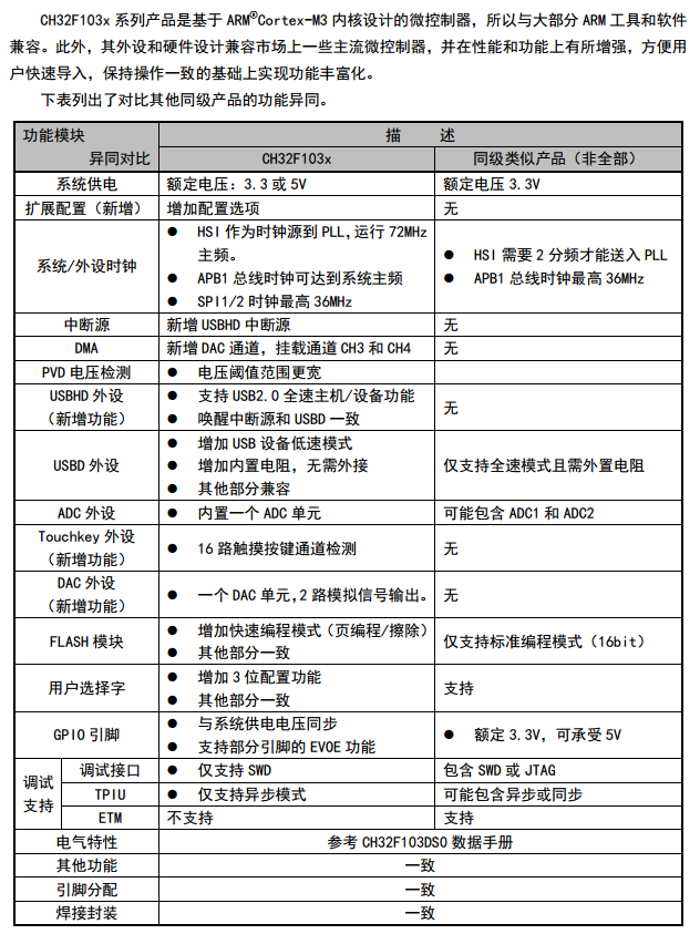
Comparing STM32 with CH32, I was surprised to find that CH32 also has DAC function. According to the official library, there are two signal transmitter codes, as follows:
/********************************** (C) COPYRIGHT *******************************
* File Name          : main.c
* Author             : WCH
* Version            : V1.0.0
* Date               : 2019/10/15
* Description        : Main program body.
*******************************************************************************/
#include "debug.h"
#include "math.h"
/* Global define */
#define LED PCout(13)
#define buf_len 50
/* Global Variable */
u32 DAC_Buf[buf_len];

/*******************************************************************************
* Function Name  : Gpio_Init
* Description    : Initializes GPIO collection.
* Input          : None
* Return         : None
*******************************************************************************/
void Gpio_Init(void)
{
	GPIO_InitTypeDef  GPIO_InitStructure;
	RCC_APB2PeriphClockCmd(RCC_APB2Periph_GPIOC,ENABLE);

	GPIO_InitStructure.GPIO_Pin = GPIO_Pin_13;
	GPIO_InitStructure.GPIO_Mode = GPIO_Mode_Out_PP;
	GPIO_InitStructure.GPIO_Speed = GPIO_Speed_50MHz;
	GPIO_Init(GPIOC, &GPIO_InitStructure);
	GPIO_SetBits(GPIOC,GPIO_Pin_13);
}

/*******************************************************************************
* Function Name  : Dac_Init
* Description    : Initializes DAC collection.
* Input          : None
* Return         : None
*******************************************************************************/
void Dac_Init(void)
{
	GPIO_InitTypeDef GPIO_InitStructure;
	DAC_InitTypeDef DAC_InitType;

	RCC_APB2PeriphClockCmd(RCC_APB2Periph_AFIO|RCC_APB2Periph_GPIOA, ENABLE );
	RCC_APB1PeriphClockCmd(RCC_APB1Periph_DAC, ENABLE );

	GPIO_InitStructure.GPIO_Pin = GPIO_Pin_4;
	GPIO_InitStructure.GPIO_Mode = GPIO_Mode_AF_PP;
	GPIO_InitStructure.GPIO_Speed = GPIO_Speed_50MHz;
	GPIO_Init(GPIOA, &GPIO_InitStructure);
	GPIO_SetBits(GPIOA,GPIO_Pin_4);

	DAC_InitType.DAC_Trigger=DAC_Trigger_T3_TRGO;
	DAC_InitType.DAC_WaveGeneration=DAC_WaveGeneration_None;
	DAC_InitType.DAC_OutputBuffer=DAC_OutputBuffer_Disable ;
	DAC_Init(DAC_Channel_1,&DAC_InitType);

	DAC_Cmd(DAC_Channel_1, ENABLE);
	DAC_DMACmd(DAC_Channel_1,ENABLE);
}


/*******************************************************************************
* Function Name  : DAC1_DMA_INIT
* Description    : Initializes DMA of DAC1 collection.
* Input          : None
* Return         : None
*******************************************************************************/
void DAC1_DMA_Init(void)
{
	DMA_InitTypeDef DMA_InitStructure;
	RCC_AHBPeriphClockCmd(RCC_AHBPeriph_DMA1, ENABLE);

	DMA_StructInit( &DMA_InitStructure);
	/* Note:DAC1--->DMA1.CH3   DAC2--->DMA1.CH4 */
	DMA_InitStructure.DMA_PeripheralBaseAddr = (u32)&(DAC->R12BDHR1);
	DMA_InitStructure.DMA_MemoryBaseAddr = (u32)DAC_Buf;
	DMA_InitStructure.DMA_DIR = DMA_DIR_PeripheralDST;
	DMA_InitStructure.DMA_BufferSize = buf_len*4;
	DMA_InitStructure.DMA_PeripheralInc = DMA_PeripheralInc_Disable;
	DMA_InitStructure.DMA_MemoryInc = DMA_MemoryInc_Enable;
	DMA_InitStructure.DMA_PeripheralDataSize = DMA_PeripheralDataSize_HalfWord;
	DMA_InitStructure.DMA_MemoryDataSize = DMA_PeripheralDataSize_Word;
	DMA_InitStructure.DMA_Mode = DMA_Mode_Circular;
	DMA_InitStructure.DMA_Priority = DMA_Priority_VeryHigh;
	DMA_InitStructure.DMA_M2M = DMA_M2M_Disable;

	DMA_Init(DMA1_Channel3, &DMA_InitStructure);
	DMA_Cmd(DMA1_Channel3, ENABLE);
}

/*******************************************************************************
* Function Name  : DAC_Data_Init
* Description    : Initializes Data of DMA.
* Input          : None
* Return         : None
*******************************************************************************/
void DAC_Data_Init(void)
{
	uint32_t Idx = 0;
	for (Idx = 0; Idx < buf_len; Idx++)
	{
		DAC_Buf[Idx] = 2000*sin(Idx*3.14159265*2/buf_len)+2048;
	}
}

/*******************************************************************************
* Function Name  : TIM3_Init
* Description    : Initializes TIM3 collection.
* Input          : arr: TIM_Period
*                  psc: TIM_Prescaler
* Return         : None
*******************************************************************************/
void TIM3_Init(u16 arr,u16 psc)
{
	TIM_TimeBaseInitTypeDef  TIM_TimeBaseStructure;
	GPIO_InitTypeDef GPIO_InitStructure;
	TIM_OCInitTypeDef TIM_OCInitStructure;

	RCC_APB1PeriphClockCmd(RCC_APB1Periph_TIM3, ENABLE);
	RCC_APB2PeriphClockCmd(RCC_APB2Periph_AFIO|RCC_APB2Periph_GPIOA,ENABLE);

	GPIO_InitStructure.GPIO_Pin=GPIO_Pin_6;
	GPIO_InitStructure.GPIO_Mode=GPIO_Mode_AF_PP;	//Multiplexed push-pull output
	GPIO_InitStructure.GPIO_Speed=GPIO_Speed_50MHz;
	GPIO_Init(GPIOA,&GPIO_InitStructure);

	TIM_TimeBaseStructure.TIM_Period = arr-1;
	TIM_TimeBaseStructure.TIM_Prescaler = psc-1;
	TIM_TimeBaseStructure.TIM_ClockDivision = TIM_CKD_DIV1;
	TIM_TimeBaseStructure.TIM_CounterMode = TIM_CounterMode_Up;
	TIM_TimeBaseInit(TIM3, &TIM_TimeBaseStructure);

	TIM_SelectOutputTrigger(TIM3, TIM_TRGOSource_Update);

	TIM_OCInitStructure.TIM_OCMode = TIM_OCMode_PWM1;//Detailed description below
	TIM_OCInitStructure.TIM_OutputState = TIM_OutputState_Enable;//TIM_OutputState_Disable;
	TIM_OCInitStructure.TIM_Pulse = arr>>1;
	TIM_OCInitStructure.TIM_OCPolarity = TIM_OCPolarity_Low;//If PWM1 is Low, PWM2 is High
	TIM_OC1Init(TIM3, &TIM_OCInitStructure);
	TIM_Cmd(TIM3, ENABLE);
}


/*******************************************************************************
* Function Name  : main
* Description    : Main program.
* Input          : None
* Return         : None
*******************************************************************************/
int main(void)
{
	NVIC_PriorityGroupConfig(NVIC_PriorityGroup_2);
	Delay_Init();

	Gpio_Init();
	Dac_Init();
	DAC_Data_Init();
	DAC1_DMA_Init();
	TIM3_Init(10,36); //Overflow rate 200kHz generates 1kHz sine wave

	while(1)
	{
		LED = !LED;
		Delay_Ms(500);
	}
}
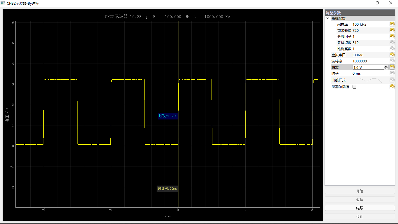
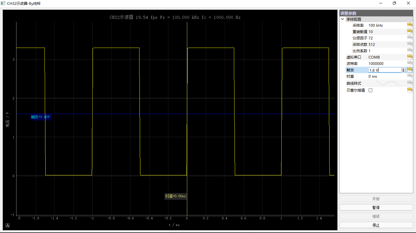
2 square wave test
2.1 1kHz square wave quantity results
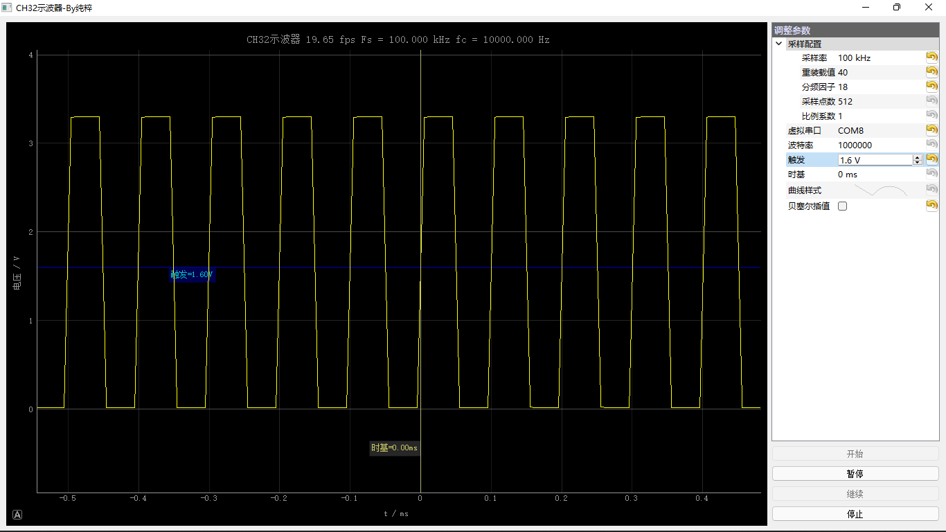
2.2 10kHz square wave quantity results
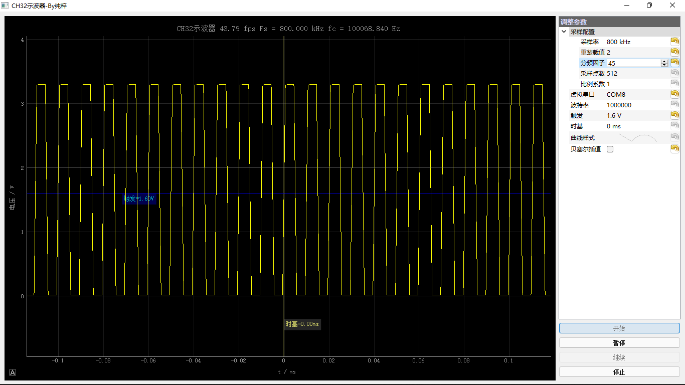
2.3 results of 100kHz square wave quantity
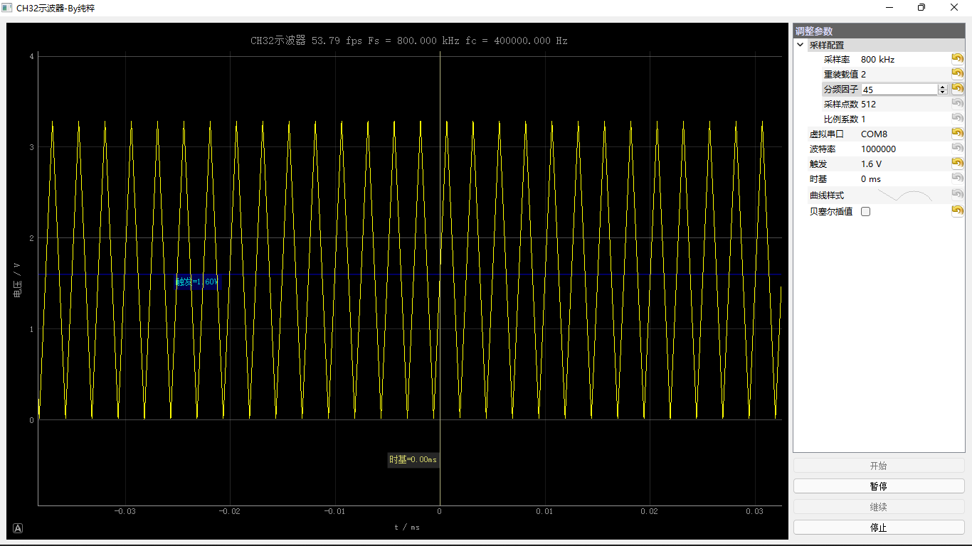
2.4 400kHz square wave quantity results
3 sine wave test
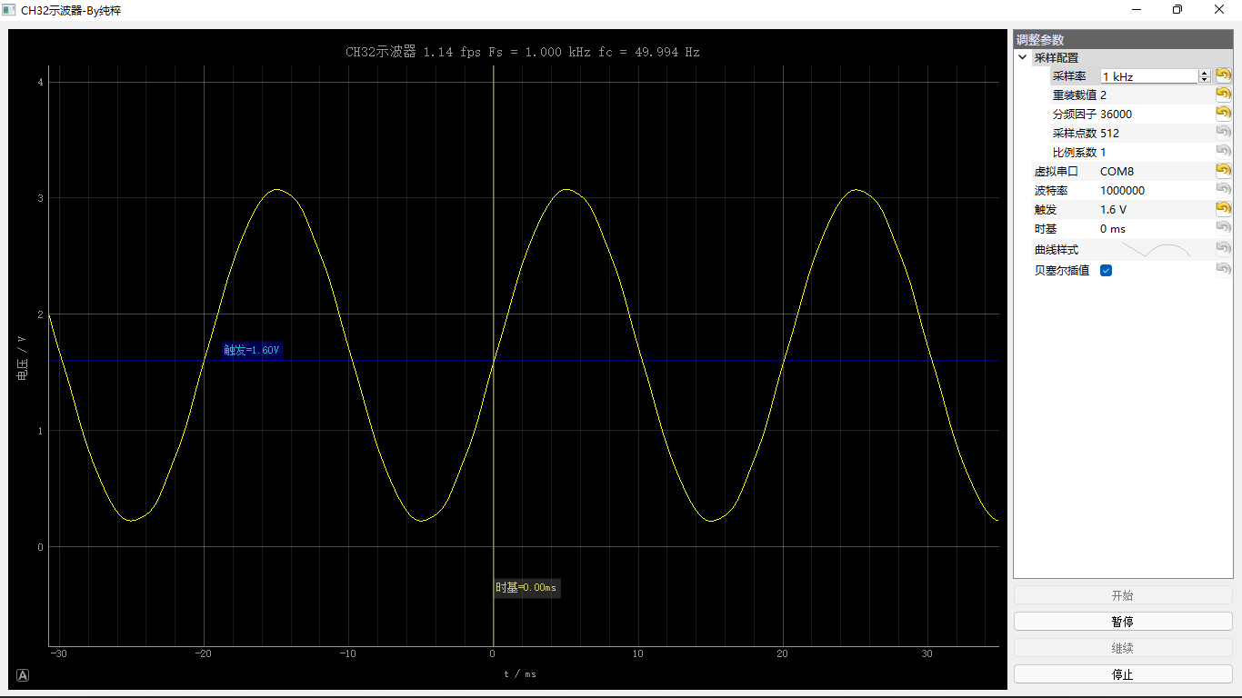
3.1 50Hz sine wave quantity results
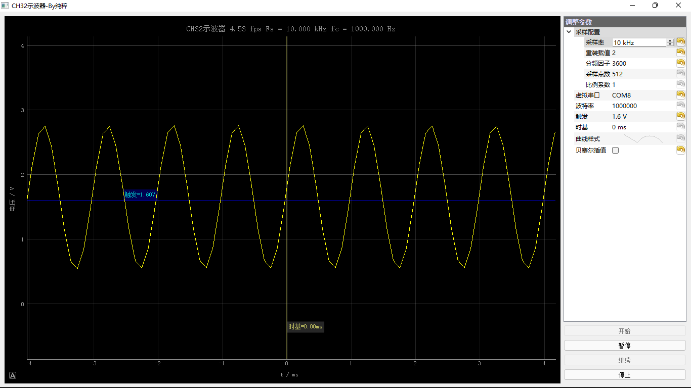
3.2 1kHz sine wave quantity results
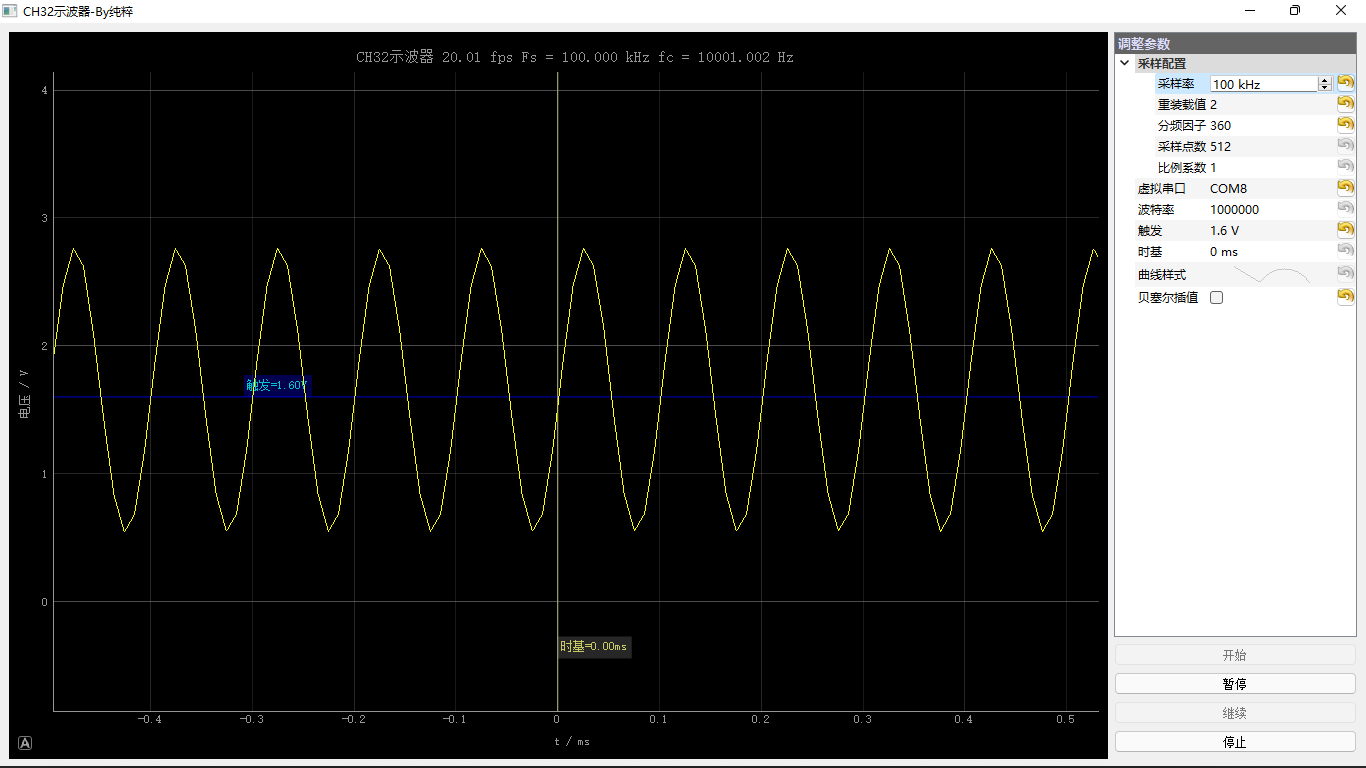
3.3 10kHz sine wave quantity results
Tip: CH32 DAC is inconvenient to generate high-frequency sine wave. The measurement results are for reference only