1. Network planning
1.1 network topology
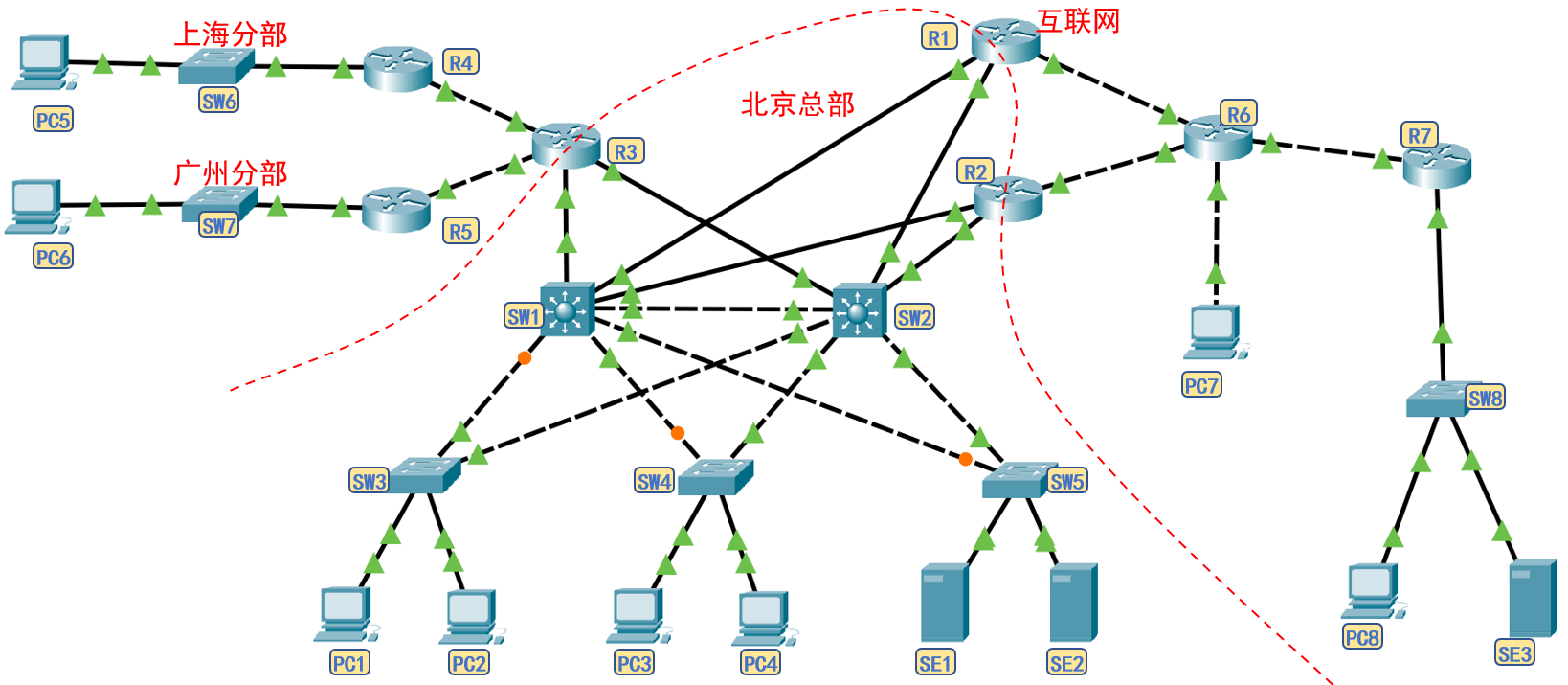
1.2 network planning
- Overall planning: the company is headquartered in Beijing and has branches in Shanghai and Guangzhou, which are connected to the headquarters through special lines. It is assumed that the internal and external network segments are planned as follows.
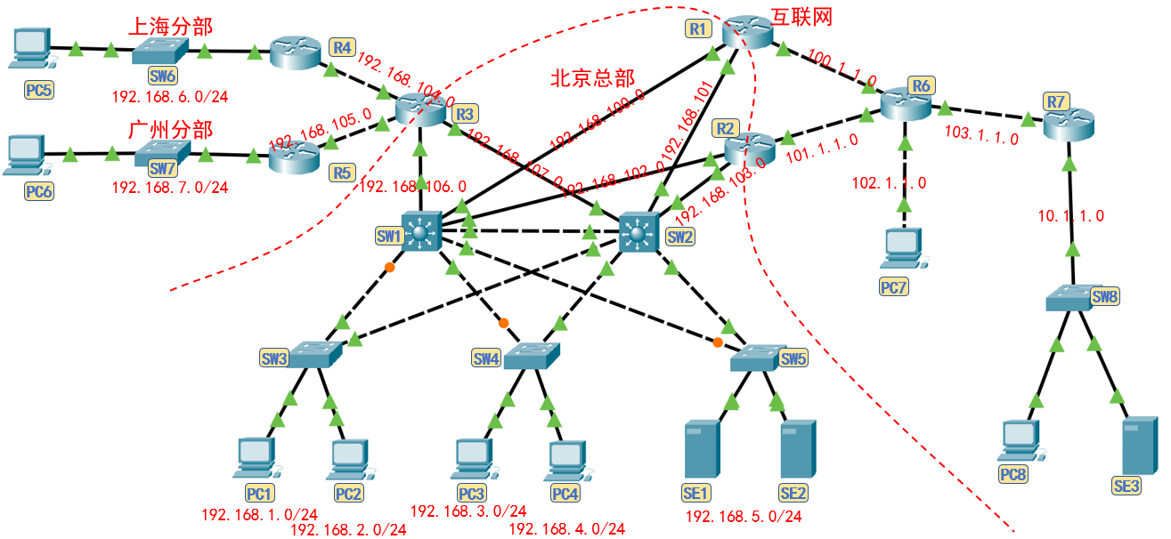
- Department Network: VLAN s and network segments of the company's headquarters and distributed departments are as follows:
| position | department | Representative machine | Virtual LAN | Network segment |
|---|---|---|---|---|
| Beijing | Marketing Department | PC1 | VLAN10 | 192.168.1.0/24 |
| Beijing | Sales Department | PC2 | VLAN20 | 192.168.2.0/24 |
| Beijing | Technology Department | PC3 | VLAN30 | 192.168.3.0/24 |
| Beijing | Finance Department | PC4 | VLAN40 | 192.168.4.0/24 |
| Beijing | DNS, DHCP server | SE1 | VLAN50 | 192.168.5.0/24 |
| Beijing | WWW server | SE2 | VLAN50 | 192.168.5.0/24 |
| Shanghai | Sales Department | PC5 | VLAN20 | 192.168.6.0/24 |
| Guangzhou | Sales Department | PC6 | VLAN20 | 192.168.7.0/24 |
- Internal routing network:
| Interface 1 | Interface 2 | Network segment |
|---|---|---|
| R1 f0/0 | SW1 f0/5 | 192.168.100.0/24 |
| R1 f0/1 | SW2 f0/5 | 192.168.101.0/24 |
| R2 f0/0 | SW1 f0/6 | 192.168.102.0/24 |
| R2 f0/1 | SW2 f0/6 | 192.168.103.0/24 |
| R3 f0/0 | R4 f0/1 | 192.168.104.0/24 |
| R3 f0/1 | R5 f0/1 | 192.168.105.0/24 |
| R3 f1/0 | SW1 f0/7 | 192.168.106.0/24 |
| R3 f1/1 | SW2 f0/7 | 192.168.107.0/24 |
- External network:
| Interface 1 | Interface 2 | Network segment |
|---|---|---|
| R1 f1/0 | R6 f0/0 | 100.1.1.0/24 |
| R2 f1/0 | R6 f0/1 | 101.1.1.0/24 |
| PC7 f0 | R6 f1/0 | 102.1.1.0/24 |
| R7 f0/0 | R6 f1/1 | 103.1.1.0/24 |
- HSRP demand or floating routing analysis: each VLAN of the headquarters is connected to two core switches, and 5 pairs of HSRP groups need to be set; Two core switches are connected to three routers, and three pairs of floating routes need to be set.
| Configuration location 1 | IP | Configuration location 2 | IP | HSRP group number | Virtual IP |
|---|---|---|---|---|---|
| SW1 VLAN10 | 192.168.1.252 | SW2 VLAN10 | 192.168.1.253 | 10 | 192.168.1.254 |
| SW1 VLAN20 | 192.168.2.252 | SW2 VLAN20 | 192.168.2.253 | 20 | 192.168.2.254 |
| SW1 VLAN30 | 192.168.3.252 | SW2 VLAN30 | 192.168.3.253 | 30 | 192.168.3.254 |
| SW1 VLAN40 | 192.168.4.252 | SW2 VLAN40 | 192.168.4.253 | 40 | 192.168.4.254 |
| SW1 VLAN50 | 192.168.5.252 | SW2 VLAN50 | 192.168.5.253 | 50 | 192.168.5.254 |
- The IP planning for each interface is as follows:

2 experimental requirements
2.1 server functions
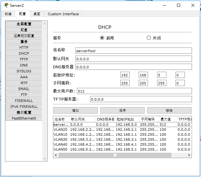
- SE1 provides DHCP and DNS servers for headquarters employees.
- SE2 provides Web server for intranet and intranet.
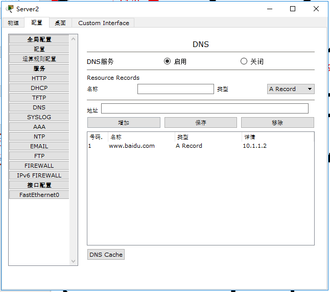
- SE3 is set as Baidu server to provide web services for internal and external networks.
2.2 host functions
- ping the whole network.
- PC1 can remotely manage all routers, core switches and switches in the company.
2.3 core switch
- SW1 and SW1 are active switches and backup switches of different network segments respectively.
- SW1 and SW2 form a loop with each layer-2 switch in the headquarters. It is required that when only one wiring fault occurs in each loop, the network can communicate normally.
2.4 router
- The setting mode of routing table shall flexibly adopt static routing table and dynamic routing table.
- R1 and R2 are active routers and backup routers of different network segments.
- Set NAT to ensure that private IP can be converted to public IP normally.
- Set ACL to prohibit branch hosts from communicating with the external network.
3. Detailed explanation of configuration process and command
The experimental configuration process is divided into three stages according to functions. The first stage requires the completion of Intranet communication, the second stage requires the completion of Intranet and Intranet communication, and the third stage requires the completion of communication restriction and remote management.
Stage 1: complete intranet interworking
Step 1.1 configure trunk interface mode for layer 2 switch
- Before configuration, it is necessary to analyze which interfaces belong to trunk interfaces, which are trunk interfaces between core switches and between core switches and layer 2 switches. There are 4 SW1 and SW2 and 2 layer-2 switches respectively.
- The interface of the core switch has layer 2 and layer 3 functions. To set its interface as the trunk interface, you need one more command than the layer 2 switch.
- When multiple interfaces on a switch need to be set as trunk ports, it is recommended to combine the settings.
'''SW1 to configure trunk Interface mode'''
en
conf t
host SW1
int range f0/1 - 4
switchport trunk encapsulation dot1q
sw m t
exit

'''SW2 to configure trunk Interface mode'''
en
conf t
host SW2
int range f0/1 - 4
switchport trunk encapsulation dot1q
sw m t
exit

'''SW3 to configure trunk Interface mode'''
en
conf t
ho SW3
int range f0/3 - 4
sw m t
exit

'''SW4 to configure trunk Interface mode'''
en
conf t
ho SW4
int f0/3
sw m t
exit
int f0/4
sw m t
exit

'''SW5 to configure trunk Interface mode'''
en
conf t
ho SW5
int f0/3
sw m t
exit
int f0/4
sw m t
exit

'''View configuration results'''
do show vlan	#If the interface is successfully configured as trunk, it will not be displayed in the vlan table.
Step 1.2 configure VTP domain and create VLAN type
- VTP can be configured in 2 core switches or 3 layer-2 switches.
- VLAN s need to be created one by one.
'''SW1 to configure VTP Domain and creation VLAN type'''
en
conf t
vtp domain qq
vlan 10
exit
vlan 20
exit
vlan 30
exit
vlan 40
exit
vlan 50
exit

'''View configuration results'''
do show vlan	#Check whether each switch successfully generates the required VLAN according to VTP
Step 1.3 divide the interface to the corresponding VLAN
- For layer 2 switches, each interface needs to be set according to VLAN classification.
'''by SW3 Dividing interfaces to corresponding VLAN'''
en
conf t
int f0/1
sw ac vlan 10
int f0/2
sw ac vlan 20
exit

'''by SW4 Dividing interfaces to corresponding VLAN'''
en
conf t
int f0/1
sw ac vlan 30
int f0/2
sw ac vlan 40
exit

'''by SW5 Dividing interfaces to corresponding VLAN'''
en
conf t
int f0/1
sw ac vlan 50
int f0/2
sw ac vlan 50
exit

'''View configuration results'''
do show vlan	#Check whether each switch successfully generates the required VLAN according to VTP
Step 1.4 configure IP for core switch
- The core switch creates virtual interfaces and configures IP for each VLAN. Because a VLAN corresponds to two virtual interface gateways, it is necessary to build an HSRP group. It is recommended that the interface gateways end with. 252 and. 253 respectively. When setting the HSRP, the virtual IP added is. 254.
- Since the DHCP request is broadcast and cannot be propagated between different VLAN s, DHCP relay needs to be set to unicast the broadcast request to the DHCP server.
- Upgrade the core switch interface and configure IP.
- Remember to use ip routing to enable the layer 3 switch function
'''by SW1 Create virtual interface configuration IP And set DHCP relay'''
en
conf t
ip routing
int vlan 10
no shut
ip add 192.168.1.252 255.255.255.0
ip helper-address 192.168.5.1
exit
int vlan 20
no shut
ip add 192.168.2.252 255.255.255.0
ip helper-address 192.168.5.1
exit
int vlan 30
no shut
ip add 192.168.3.252 255.255.255.0
ip helper-address 192.168.5.1
exit
int vlan 40
no shut
ip add 192.168.4.252 255.255.255.0
ip helper-address 192.168.5.1
exit
int vlan 50
no shut
ip add 192.168.5.252 255.255.255.0
ip helper-address 192.168.5.1
exit

'''by SW1 Upgrade the interface to a three-level interface and configure it IP'''
en
conf t
int f0/5
no switchport
no shut
ip add 192.168.100.1 255.255.255.0
exit
int f0/6
no switchport
no shut
ip add 192.168.102.1 255.255.255.0
exit
int f0/7
no switchport
no shut
ip add 192.168.106.1 255.255.255.0
exit


'''by SW2 Create virtual interface configuration IP And set DHCP relay'''
en
conf t
ip routing
int vlan 10
no shut
ip add 192.168.1.253 255.255.255.0
ip helper-address 192.168.5.1
exit
int vlan 20
no shut
ip add 192.168.2.253 255.255.255.0
ip helper-address 192.168.5.1
exit
int vlan 30
no shut
ip add 192.168.3.253 255.255.255.0
ip helper-address 192.168.5.1
exit
int vlan 40
no shut
ip add 192.168.4.253 255.255.255.0
ip helper-address 192.168.5.1
exit
int vlan 50
no shut
ip add 192.168.5.253 255.255.255.0
ip helper-address 192.168.5.1
exit

'''by SW2 Upgrade the interface to a three-level interface and configure it IP'''
en
conf t
int f0/5
no switchport
no shut
ip add 192.168.101.1 255.255.255.0
exit
int f0/6
no switchport
no shut
ip add 192.168.103.1 255.255.255.0
exit
int f0/7
no switchport
no shut
ip add 192.168.107.1 255.255.255.0
exit

'''View configuration results'''
show ip int b	#Check the vlan and entity interface IP
Step 1.5 create a hot backup for the core switch
- In the previous step, when the core switch creates a virtual interface for each VLAN and configures the IP, because a VLAN corresponds to two virtual interface gateways, it is necessary to build an HSRP group. It is recommended that the interface gateways end with. 252 and. 253 respectively, and the virtual IP added during HSRP setting is. 254.
- In order to share the load of two core switches during normal operation: SW1 is the active core switch of VLAN 10, 20, 30 and 40 and the backup core switch of VLAN 50; SW2 serves as the backup core switch of VLAN 10, 20, 30 and 40 and the active core switch of VLAN 50.
- HSRP judges whether SW1 is enabled. It needs to track the status of f0/5 and f0/6 interfaces. When both interfaces are down, switch the core switch. When one interface is down, the priority will be reduced by 10 (I don't know whether different platforms are consistent). Try to set the priority of backup switch to 195 and 185 to see the effect after disconnection; The same is true for SW2.
'''by SW1 establish HSRP Hot backup'''
en
conf t
int vlan 10
stan 10 ip 192.168.1.254
stan 10 prior 200
stan 10 preempt
stan 10 track f0/5
stan 10 track f0/6
exit
int vlan 20
stan 20 ip 192.168.2.254
stan 20 prior 200
stan 20 preempt
stan 20 track f0/5
stan 20 track f0/6
exit
int vlan 30
stan 30 ip 192.168.3.254
stan 30 prior 200
stan 30 preempt
stan 30 track f0/5
stan 30 track f0/6
exit
int vlan 40
stan 40 ip 192.168.4.254
stan 40 prior 200
stan 40 preempt
stan 40 track f0/5
stan 40 track f0/6
exit
int vlan 50
stan 50 ip 192.168.5.254
stan 50 prior 195
stan 50 preempt
stan 50 track f0/5
stan 50 track f0/6
exit

'''by SW2 establish HSRP Hot backup'''
en
conf t
int vlan 10
stan 10 ip 192.168.1.254
stan 10 prior 195
stan 10 preempt
stan 10 track f0/5
stan 10 track f0/6
exit
int vlan 20
stan 20 ip 192.168.2.254
stan 20 prior 195
stan 20 preempt
stan 20 track f0/5
stan 20 track f0/6
exit
int vlan 30
stan 30 ip 192.168.3.254
stan 30 prior 195
stan 30 preempt
stan 30 track f0/5
stan 30 track f0/6
exit
int vlan 40
stan 40 ip 192.168.4.254
stan 40 prior 195
stan 40 preempt
stan 40 track f0/5
stan 40 track f0/6
exit
int vlan 50
stan 50 ip 192.168.5.254
stan 50 prior 200
stan 50 preempt
stan 50 track f0/5
stan 50 track f0/6
exit

'''View configuration results'''
show standby breif	#Check the HSRP configuration results. The disconnection test priority needs to be after the subsequent router configuration

'''ping test'''
Manual as PC1 And PC2 to configure IP,Test two VLAN Whether the communication can be normal.
stay PT6.0 Version here ping No, because the simulation platform exists bug,At 8.0 Version can ping Pass.
Step 1.6 router configuration IP
- Configure IP for each interface of the router according to the network planning.
'''by R1 Interface configuration IP'''
en
conf t
ho R1
int f0/0
no shut
ip add 192.168.100.2 255.255.255.0
exit
int f0/1
no shut
ip add 192.168.101.2 255.255.255.0
exit
int f1/0
no shut
ip add 100.1.1.1 255.255.255.0
exit

'''by R2 Interface configuration IP'''
en
conf t
ho R2
int f0/0
no shut
ip add 192.168.102.2 255.255.255.0
exit
int f0/1
no shut
ip add 192.168.103.2 255.255.255.0
exit
int f1/0
no shut
ip add 101.1.1.1 255.255.255.0
exit

'''by R3 Interface configuration IP'''
en
conf t
ho R3
int f0/0
no shut
ip add 192.168.104.2 255.255.255.0
exit
int f0/1
no shut
ip add 192.168.105.2 255.255.255.0
exit
int f1/0
no shut
ip add 192.168.106.2 255.255.255.0
exit
int f1/1
no shut
ip add 192.168.107.2 255.255.255.0
exit

'''by R4 Interface configuration IP'''
en
conf t
ho R4
int f0/0
no shut
ip add 192.168.6.254 255.255.255.0
exit
int f0/1
no shut
ip add 192.168.104.1 255.255.255.0
exit

'''by R5 Interface configuration IP'''
en
conf t
ho R5
int f0/0
no shut
ip add 192.168.7.254 255.255.255.0
exit
int f0/1
no shut
ip add 192.168.105.1 255.255.255.0
exit

'''by R6 Interface configuration IP'''
en
conf t
ho R6
int f0/0
no shut
ip add 100.1.1.2 255.255.255.0
exit
int f0/1
no shut
ip add 101.1.1.2 255.255.255.0
exit
int f1/0
no shut
ip add 102.1.1.254 255.255.255.0
exit
int f1/1
no shut
ip add 103.1.1.2 255.255.255.0
exit

'''by R7 Interface configuration IP'''
en
conf t
ho R7
int f0/0
no shut
ip add 103.1.1.1 255.255.255.0
exit
int f0/1
no shut
ip add 10.1.1.254 255.255.255.0
exit

'''View configuration results'''
show standby breif	#The priority of Disconnection Test shall be determined after subsequent router configuration
Step 1.7 router configuration routing table
- Because it is easy to form paths with the same priority when using RIP dynamic routing configuration, this experiment adopts the way of static routing table configuration.
- For routing table entry priority, static routing > dynamic routing > default routing.
- It is recommended to use show ip router to view the direct connection routing tables and configure them.
'''by SW1 Configure static routing table'''
en
conf t
ip route 192.168.6.0 255.255.255.0 192.168.106.2
ip route 192.168.7.0 255.255.255.0 192.168.106.2
ip route 192.168.104.0 255.255.255.0 192.168.106.2
ip route 192.168.105.0 255.255.255.0 192.168.106.2
ip route 0.0.0.0 0.0.0.0 192.168.100.2
ip route 0.0.0.0 0.0.0.0 192.168.102.2 2

'''by SW2 Configure static routing table'''
en
conf t
ip route 192.168.6.0 255.255.255.0 192.168.107.2
ip route 192.168.7.0 255.255.255.0 192.168.107.2
ip route 192.168.104.0 255.255.255.0 192.168.107.2
ip route 192.168.105.0 255.255.255.0 192.168.107.2
ip route 0.0.0.0 0.0.0.0 192.168.101.2
ip route 0.0.0.0 0.0.0.0 192.168.103.2 2

'''by R3 to configure RIP Static routing table'''
en
conf t
ip route 192.168.6.0 255.255.255.0 192.168.104.1
ip route 192.168.7.0 255.255.255.0 192.168.105.1
ip route 0.0.0.0 0.0.0.0 192.168.106.1
ip route 0.0.0.0 0.0.0.0 192.168.107.1 2

'''by R4 Configure default routing table'''
en
conf t
ip route 0.0.0.0 0.0.0.0 192.168.104.2

'''by R5 Configure static routing table'''
en
conf t
ip route 0.0.0.0 0.0.0.0 192.168.105.2

'''View configuration results'''
show ip router	#Check whether the routing table converges

'''ping test'''
Manual as PC1 And PC6 to configure IP,Test whether the communication between headquarters and branches can be normal.
Step 1.8 PC and server configuration
- Perform manual IP configuration for PC5 and PC6.
- Configure the IP of DNS and DHCP servers, configure the DHCP address pool, and finally configure the DNS server.
Step 1.9 test whether the intranet ping can be completed
Test other hosts and servers in the intranet with PC1.
Phase 2: complete the interworking of the whole network
Step 2.1 configure the static routing table for the external router interface
- As one of the company's general gateways, R1 is internally connected to two core switches, with R1 and SW1 as active links and R1 and SW2 as backup links, which are controlled by floating routes; Connect R6 with the outside, and use the default route to control the external network segment.
- R2, as one of the company's general gateways, is internally connected to two core switches, with R2 and SW2 as active links and R2 and SW1 as backup links, which are controlled by floating routes; Connect R6 with the outside, and use the default route to control the external network segment.
- R6 does not need to know the internal network segment of the company, and temporarily regards 10.1.1.0/24 as a public network for experiment.
'''by R1 Configure static routing table'''
en
conf t
ip route 0.0.0.0 0.0.0.0 100.1.1.2
ip route 192.168.1.0 255.255.255.0 192.168.100.1
ip route 192.168.2.0 255.255.255.0 192.168.100.1
ip route 192.168.3.0 255.255.255.0 192.168.100.1
ip route 192.168.4.0 255.255.255.0 192.168.100.1
ip route 192.168.5.0 255.255.255.0 192.168.100.1
ip route 192.168.6.0 255.255.255.0 192.168.100.1
ip route 192.168.7.0 255.255.255.0 192.168.100.1
ip route 192.168.104.0 255.255.255.0 192.168.100.1
ip route 192.168.105.0 255.255.255.0 192.168.100.1
ip route 192.168.106.0 255.255.255.0 192.168.100.1
ip route 192.168.107.0 255.255.255.0 192.168.100.1
ip route 192.168.1.0 255.255.255.0 192.168.101.1 2
ip route 192.168.2.0 255.255.255.0 192.168.101.1 2
ip route 192.168.3.0 255.255.255.0 192.168.101.1 2
ip route 192.168.4.0 255.255.255.0 192.168.101.1 2
ip route 192.168.5.0 255.255.255.0 192.168.101.1 2
ip route 192.168.6.0 255.255.255.0 192.168.101.1 2
ip route 192.168.7.0 255.255.255.0 192.168.101.1 2
ip route 192.168.104.0 255.255.255.0 192.168.101.1 2
ip route 192.168.105.0 255.255.255.0 192.168.101.1 2
ip route 192.168.106.0 255.255.255.0 192.168.101.1 2
ip route 192.168.107.0 255.255.255.0 192.168.101.1 2

'''by R2 Configure static routing table'''
en
conf t
ip route 0.0.0.0 0.0.0.0 101.1.1.2
ip route 192.168.1.0 255.255.255.0 192.168.103.1
ip route 192.168.2.0 255.255.255.0 192.168.103.1
ip route 192.168.3.0 255.255.255.0 192.168.103.1
ip route 192.168.4.0 255.255.255.0 192.168.103.1
ip route 192.168.5.0 255.255.255.0 192.168.103.1
ip route 192.168.6.0 255.255.255.0 192.168.103.1
ip route 192.168.7.0 255.255.255.0 192.168.103.1
ip route 192.168.104.0 255.255.255.0 192.168.103.1
ip route 192.168.105.0 255.255.255.0 192.168.103.1
ip route 192.168.106.0 255.255.255.0 192.168.103.1
ip route 192.168.107.0 255.255.255.0 192.168.103.1
ip route 192.168.1.0 255.255.255.0 192.168.102.1 2
ip route 192.168.2.0 255.255.255.0 192.168.102.1 2
ip route 192.168.3.0 255.255.255.0 192.168.102.1 2
ip route 192.168.4.0 255.255.255.0 192.168.102.1 2
ip route 192.168.5.0 255.255.255.0 192.168.102.1 2
ip route 192.168.6.0 255.255.255.0 192.168.102.1 2
ip route 192.168.7.0 255.255.255.0 192.168.102.1 2
ip route 192.168.104.0 255.255.255.0 192.168.102.1 2
ip route 192.168.105.0 255.255.255.0 192.168.102.1 2
ip route 192.168.106.0 255.255.255.0 192.168.102.1 2
ip route 192.168.107.0 255.255.255.0 192.168.102.1 2

'''by R6 Configure static routing table'''
en
conf t
ip route 0.0.0.0 0.0.0.0 103.1.1.1

'''by R7 Configure static routing table'''
en
conf t
ip route 0.0.0.0 0.0.0.0 103.1.1.2

'''View configuration results'''
show ip router	#Check whether the routing table converges

'''ping test'''
test PC1 Can you ping through R1,R2 On the interface IP.
test PC8 Can you ping through R1,R2 On external interface IP.
Step 2.2 set NAT conversion table for general routing interface
- It is defined according to the internal and external network directions of the interfaces on routers R1 and R2. f0/0 and f0/1 are internal network interfaces and f1/0 are external network interfaces.
'''by R1 to configure NAT Convert the table, set the intranet segment rules and apply them to the extranet interface'''
en
conf t
int f0/0
ip nat inside
exit
int f0/1
ip nat inside
exit
int f1/0
ip nat outside
exit
acc 1 permit 192.168.0.0 0.0.255.255
ip nat inside source list 1 int f1/0 overload

'''by R2 to configure NAT Convert the table, set the intranet segment rules and apply them to the extranet interface'''
en
conf t
int f0/0
ip nat inside
exit
int f0/1
ip nat inside
exit
int f1/0
ip nat outside
exit
acc 1 permit 192.168.0.0 0.0.255.255
ip nat inside source list 1 int f1/0 overload

'''ping test'''
test PC1 Can you ping through PC8 On the interface IP.
Step 2.3 network structure robustness test
- Try to ping PC1 with PC8, but fail to ping because you don't know where to route with private IP as the target address on the Internet.
- Try pinging PC8 with PC1, and you can ping because the public-private IP address conversion has been completed at the gateway.
- Use PC1 to ping PC8 all the time, ping -t 10.1.1.1, and disconnect the following lines to try whether the communication is normal.
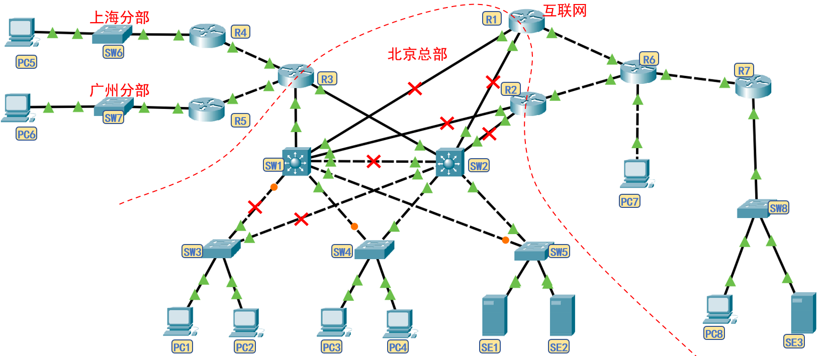
- When the network cable is disconnected to the following structure, although it seems that there is still a link between PC1 and PC8, it is not feasible in principle. Since SW1 has been completely disconnected from R1R2, its priority is lower than SW2, that is, the active gateway in the HSRP group of gateway 192.168.1.254 corresponding to PC1 should be 192.168.1.253, but PC1 has been disconnected from 192.168.1.253, so it cannot ping with PC8.
Phase 3: complete restriction and remote management
On the basis of completing the interworking of the whole network, other additional functions are completed.
Step 3.1 packet filtering: ACL table configuration
- The network segments that need to restrict the communication function mainly include 192.168.6.0/24 and 192.168.7.0/24, which restrict their communication with the external network.
- Idea 1: the standard ACL table can be set on R1 and R2 interfaces. When the source IP address meets 192.168.6.0/24 and 192.168.7.0/24, it is prohibited to pass.
- Idea 2: you can also set the extended ACL table on the router corresponding to the 192.168.6.0/24 and 192.168.7.0/24 network segments, allowing only the data frames whose target address is the intranet network segment to pass through, which is more troublesome than the previous step.
- Idea 3: when configuring the routing table in R3 and R4, do not configure the default routing table.
- Because the expanded ACL function is more flexible and convenient for later adjustment and modification of the named ACL table, the named expanded ACL table is configured according to idea 1 below.
'''by R1 to configure ACL'''
en
conf t
ip access-list extended deny-to-internet
deny ip 192.168.6.0 0.255.255.255 any
deny ip 192.168.7.0 0.255.255.255 any
petmit ip any any
exit
int f1/0
ip access-group deny-to-internet out
exit

'''by R2 to configure NAT Convert the table, set the intranet segment rules and apply them to the extranet interface'''
en
conf t
ip access-list extended deny-to-internet
deny ip 192.168.6.0 0.255.255.255 any
deny ip 192.168.7.0 0.255.255.255 any
petmit ip any any
exit
int f1/0
ip access-group deny-to-internet out
exit

'''ping test'''
Successfully blocked the branch from accessing the Internet.
Step 3.2 remote management of network equipment: SSH
- Considering that Telnet port data is encrypted, SSH is used for remote management in this experiment.
- For the core switch and router, the upper interface is used to configure the IP address, and each interface IP can be used to remotely manage the core switch and router.
- For layer 2 switches, you need to use its built-in virtual host to set the IP address for remote management.
'''by SW1,SW2,R1,R2,R3,R4,R5 Configure password and enable remote management mode'''
en
conf t
enable password 654321
ip domain-name xx.qq.com
crypto key generate rsa
 Manually enter digits
username libai password libai
username zhugeliang password zhugeliang
line vty 0 3
transport input ssh
login local
exit

'''Remote management test'''
Core switches and routers can be controlled remotely.
4 precautions and deficiencies
- In this experiment, the packer tracer 8.0 platform is used for the experiment. There is a bug in setting HSRP for the core switch with version 6.0.
- The connection between R3 and SW2 is chicken rib and can only work when R3 and SW1 are disconnected. Because the interface f0/7 of SW1 cannot track other disconnected States, for example, when R1 fails, the branch host cannot automatically switch to R2 to access the Internet. How should this function be implemented?
- How to remotely control the layer 2 switch?
5 Summary
- Think about how HSRP and floating routing can play a backup role in case of route failure.
- Master complete network configuration ideas.
- Master relevant commands.