1) Experimental platform: ZYNQ development board of punctual atomic navigator
2) Platform purchase address: https://item.taobao.com/item.htm?&id=606160108761
3) Full set of experimental source code + manual + video download address: http://www.openedv.com/thread-301505-1-1.html
4) Students interested in punctual atomic FPGA can add group discussion: 994244016
5) pay attention to the official account of the dot atom and get updated information.

Chapter 31 traffic light experiment
Traffic signal light is a very common public facility in life. It plays a role in dredging traffic at intersections and zebra crossings on the road. In this chapter, we will use the traffic signal light module to reproduce its function.
This chapter includes the following parts:
1.1 INTRODUCTION
1.2 experimental tasks
1.3 hardware design
1.4 program design
1.5 download verification
1.1 INTRODUCTION
Traffic lights are often composed of red, green and yellow lights. No traffic when the red light is on; When the green light is on, you can pass; When the yellow light is on, it indicates that the traffic time is over and will be converted to a red light immediately.
The traffic signal lamp to be reproduced in this experiment is the signal lamp at the intersection, which is composed of two pairs of signal lamps. The physical object of signal lamp is shown in figure 7.5.13.1:
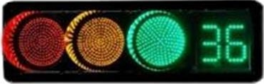
Figure 7.5.13.1 traffic lights
Figure 7.5.13.2 is a simplified schematic diagram of traffic signal lights at intersections:
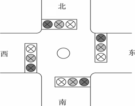
Figure 7.5.13.2 schematic diagram of intersection signal light
The lighting sequence of signal lights in a single direction is: after the red light is off, the green light is on, after the green light is off, the yellow light is on, and after the yellow light is off, the red light is on. This cycle continues. In addition, a pair of signal lights in the same direction have the same color, and the display time is the same.
In order to simulate the function of traffic lights, table 31.1.1 signal light state conversion table is made:

Table 31.1.1 state transition of traffic lights
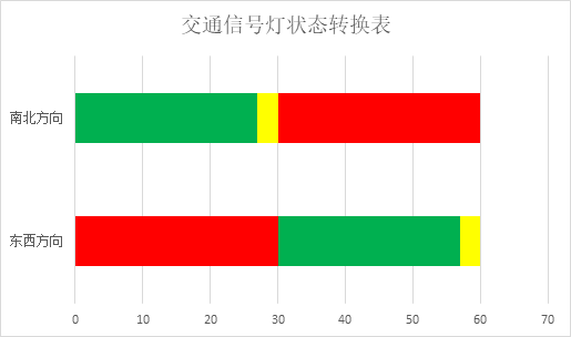
In table 31.1.1, within a set period, the red light emits for 30s, the green light emits for 27s and the yellow light emits for 3s. Taking the state of east-west direction signal as an example, the time of red light is equal to the sum of the time of yellow light and green light. Therefore, a complete state transition cycle is twice as long as the red light, that is, 60s.
Within 30s of the red signal light in the east-west direction, the north-south direction is switched from green light to yellow light; Within 30s of the red signal light in the north-south direction, the east-west direction is also switched from green to yellow. Therefore, we classify the time period when the east-west and north-south direction lights are kept in a fixed state as one state. This results in four cyclic states:
1. The red light in the east-west direction is on for 27s, the green light in the north-south direction is on for 27s, and then switch to state 2;
2. The red light in the east-west direction is on for 3s, the yellow light in the north-south direction is on for 3s, and then switch to state 3;
3. The green light in the east-west direction is on for 27s, the red light in the north-south direction is on for 27s, and then switch to state 4;
4. The yellow light in the east-west direction is on for 3s, the red light in the north-south direction is on for 3s, and then switch to state 1.
Figure 7.5.13.3 shows the state transition diagram of traffic signal lights:
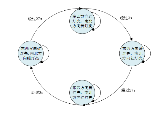
Figure 7.5.13.3 state transition diagram of traffic lights
In addition, take the east-west direction as an example: in one cycle, the red light is illuminated for 30s, the green light is illuminated for 27s, and the yellow light is illuminated for 3s. Then, during the red light emitting period, the number displayed on the nixie tube will decrease from 29 to 0; Similarly, during the green light, the number displayed on the nixie tube should decrease from 26 to 0; When the yellow light is on, the number displayed on the nixie tube decreases from 2 to 0.
1.2 experimental tasks
The experimental task of this section is to reproduce the function of traffic lights through the pilot ZYNQ development board and the external traffic light expansion module.
1.3 hardware design
The J3 expansion port on the left of our leader ZYNQ development board can be used to connect the traffic signal expansion module. The schematic diagram of the traffic signal expansion module is shown in figure 7.5.13.1.
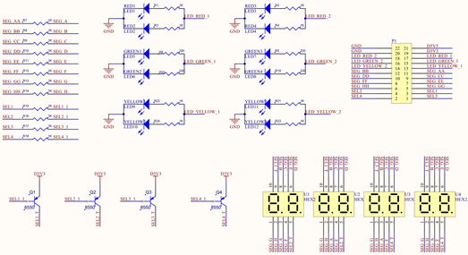
Figure 7.5.13.1 schematic diagram of traffic signal light
As can be seen from the above figure, the traffic signal expansion module has 12 LED lamps in four directions, and we use 6 LED control signals to drive 12 LED lamps. This is because the on and off states of LED lamps in east-west direction or north-south direction are always the same, so we connect LED lamps with the same color in east-west direction or south-north direction in parallel, The advantage of this design is to reduce the pin of LED control signal of traffic signal expansion module.
The four common Yang nixie tubes in the figure above correspond to four intersections respectively, and each intersection uses two nixie tubes to display the remaining time of the current state. We know that at the intersection, the time displayed by the digital tube in the east-west direction or north-south direction is always the same. Taking the east-west direction as an example, because the time displayed in the two directions is the same, the ten bits of the nixie tubes in the two directions can be controlled by the same bit selection signal, and the one bit can be controlled by the other bit selection signal. In this way, the two bit selection signals can control the lighting of the four bit nixie tubes in the east-west direction, and the nixie tubes in the north-south direction are the same. The advantage of this design is to reduce the pin of bit selection signal of traffic signal expansion module.
It should be noted that the nixie tube is driven by PNP type triode. When the base of the triode is low, the corresponding bit of the nixie tube is gated, so the bit selection signal of the traffic signal expansion module is effective at low level.
The physical map of traffic signal light is shown in figure 7.5.13.2. In this chapter, we experimentally set the direction of traffic signal light as up, north, South, West, East and right.
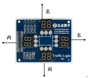
Figure 7.5.13.2 physical drawing of traffic signal light
In this experiment, the pin distribution of traffic signal lamp is shown in the table below.
Table 31.3.1 pin distribution of traffic signal test
Signal name direction pin port description
sys_clk input U18 system clock 50MHz
sys_rst_n input N16 system reset, active at low level
sel[0] output P15 nixie tube bit selection signal sel[0]
sel[1] output P16 nixie tube bit selection signal sel[1]
sel[2] output W18 nixie tube bit selection signal sel[2]
sel[3] output W19 nixie tube position selection signal sel[3]
seg_led[0] output T16 nixie tube segment a selection signal seg_led[0]
seg_led[1] output U17 nixie tube segment b selection signal seg_led[1]
seg_led[2] output V17 nixie tube segment c selection signal seg_led[2]
seg_led[3] output V18 nixie tube segment d selection signal seg_led[3]
seg_led[4] output T17 nixie tube segment e selection signal seg_led[4]
seg_led[5] output R18 nixie tube segment f selection signal seg_led[5]
seg_led[6] output Y18 nixie tube g segment selection signal seg_led[6]
seg_led[7] output Y19 nixie tube h segment selection signal seg_led[7]
led[0] output Y17 North South Yellow LED enable
led[1] output T14 north-south green LED enable
led[2] output V16 north-south red LED enable
led[3] output Y16 East-West yellow LED enable
led[4] output T15 east-west green LED enable
led[5] output W16 East West Red LED enable
The corresponding XDC constraint file is as follows:
set_property -dict {PACKAGE_PIN U18 IOSTANDARD LVCMOS33} [get_ports sys_clk]
set_property -dict {PACKAGE_PIN N16 IOSTANDARD LVCMOS33} [get_ports sys_rst_n]

set_property -dict {PACKAGE_PIN T16 IOSTANDARD LVCMOS33} [get_ports {seg_led[0]}]
set_property -dict {PACKAGE_PIN U17 IOSTANDARD LVCMOS33} [get_ports {seg_led[1]}]
set_property -dict {PACKAGE_PIN V17 IOSTANDARD LVCMOS33} [get_ports {seg_led[2]}]
set_property -dict {PACKAGE_PIN V18 IOSTANDARD LVCMOS33} [get_ports {seg_led[3]}]
set_property -dict {PACKAGE_PIN T17 IOSTANDARD LVCMOS33} [get_ports {seg_led[4]}]
set_property -dict {PACKAGE_PIN R18 IOSTANDARD LVCMOS33} [get_ports {seg_led[5]}]
set_property -dict {PACKAGE_PIN Y18 IOSTANDARD LVCMOS33} [get_ports {seg_led[6]}]
set_property -dict {PACKAGE_PIN Y19 IOSTANDARD LVCMOS33} [get_ports {seg_led[7]}]

set_property -dict {PACKAGE_PIN Y17 IOSTANDARD LVCMOS33} [get_ports {led[0]}]
set_property -dict {PACKAGE_PIN T14 IOSTANDARD LVCMOS33} [get_ports {led[1]}]
set_property -dict {PACKAGE_PIN V16 IOSTANDARD LVCMOS33} [get_ports {led[2]}]
set_property -dict {PACKAGE_PIN Y16 IOSTANDARD LVCMOS33} [get_ports {led[3]}]
set_property -dict {PACKAGE_PIN T15 IOSTANDARD LVCMOS33} [get_ports {led[4]}]
set_property -dict {PACKAGE_PIN W16 IOSTANDARD LVCMOS33} [get_ports {led[5]}]

set_property -dict {PACKAGE_PIN P15 IOSTANDARD LVCMOS33} [get_ports {sel[0]}]
set_property -dict {PACKAGE_PIN P16 IOSTANDARD LVCMOS33} [get_ports {sel[1]}]
set_property -dict {PACKAGE_PIN W18 IOSTANDARD LVCMOS33} [get_ports {sel[2]}]
set_property -dict {PACKAGE_PIN W19 IOSTANDARD LVCMOS33} [get_ports {sel[3]}]
1.4 program design
According to the experimental task, we can roughly plan the control process of the system: the traffic light control module connects the time data to be displayed to the nixie tube display module, and connects the status signal to the led light control module, and then the nixie tube display module and led light control module drive the traffic signal peripherals to work. The system block diagram is shown in figure 7.5.13.1,
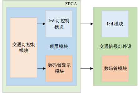
Figure 7.5.13.1 block diagram of traffic light experiment system
The port and signal connection of each module are shown in the figure below:
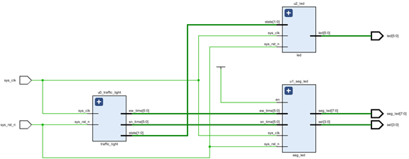
Figure 7.5.13.2 schematic diagram of top layer module of traffic signal lamp
As can be seen from the above figure, the FPGA part includes four modules: top_traffic, traffic_light, digital tube display module (seg_led) and LED light control module (LED). In the top-level module, the instantiation of the other three modules is completed, and the data transmission between each module is realized.
top_traffic: the top-level module completes the instantiation of the other three sub modules, realizes the signal connection between the sub modules, and outputs the driving signals of led lights and nixie tubes to external equipment (traffic signal peripherals).
Traffic light control module (traffic light): the traffic light control module is the core code of this experiment. This module controls the state conversion of the signal light, outputs the real-time state signal state[1:0] to the LED light control module (LED), and outputs the real-time time time data EW in the east-west and North-South directions_ Time [5:0] and sn_time[5:0] is output to the nixie tube display module (seg_led).
Digital tube display module (seg_led): receive the real-time time data EW from the traffic light control module in the east-west and North-South directions_ Time [5:0] and sn_time[5:0], and drive the corresponding nixie tube to display the data.
led control module (led): according to the received real-time status signal state[1:0], drive the led in the east-west and North-South directions to emit light.
The code of the top-level module is as follows:
1   module top_traffic(
2       input                  sys_clk   ,    //System clock signal
3       input                  sys_rst_n ,    //System reset signal
4
5       output       [3:0]     sel       ,    //Nixie tube position selection signal
6       output       [7:0]     seg_led   ,    //Nixie tube segment selection signal
7       output       [5:0]     led            //LED enable signal, red, green and yellow
8   );
9
10  //wire define
11  wire   [5:0]  ew_time;                    //East West State remaining time data
12  wire   [5:0]  sn_time;                    //Remaining time data of North-South state
13  wire   [1:0]  state  ;                    //The status of traffic lights is used to control the lighting of LED lights
14
15  //*****************************************************
16  //**                    main code
17  //*****************************************************
18  //Traffic light control module
19  traffic_light u0_traffic_light(
20      .sys_clk                (sys_clk),
21      .sys_rst_n              (sys_rst_n),
22      .ew_time                (ew_time),
23      .sn_time                (sn_time),
24      .state                  (state)
25  );
26
27  //Nixie tube display module
28  seg_led    u1_seg_led(
29      .sys_clk                (sys_clk)  ,
30      .sys_rst_n              (sys_rst_n),
31      .ew_time                (ew_time),
32      .sn_time                (sn_time),
33      .en                     (1'b1),
34      .sel                    (sel),
35      .seg_led                (seg_led)
36  );
37
38  //led lamp control module
39  led   u2_led(
40      .sys_clk                (sys_clk  ),
41      .sys_rst_n              (sys_rst_n),
42      .state                  (state    ),
43      .led                    (led      )
44  );
45
46  endmodule
In lines 22 and 23 of the code, EW output by the traffic light control module_ Time and Sn_ The time real-time time data signal is connected to the nixie tube display module; In line 24 of the code, connect the state state output by the traffic light control module to the led light control module.
The code of the traffic light control module is as follows:
1   module  traffic_light(
2       //input
3       input               sys_clk   ,        //System clock
4       input               sys_rst_n ,        //System reset
5
6       output  reg  [1:0]  state     ,        //The status of traffic lights is used to control the lighting of LED lights
7       output  reg  [5:0]  ew_time   ,        //Time data to be displayed by traffic light East-West nixie tube
8       output  reg  [5:0]  sn_time            //Time data to be displayed by traffic light north-south nixie tube
9       );
10
11  //parameter define
12  parameter  TIME_LED_Y    = 3;              //Time of yellow light
13  parameter  TIME_LED_R    = 30;             //Time of red light
14  parameter  TIME_LED_G    = 27;             //Time of green light
15  parameter  WIDTH         = 25_000_000;     //Generate a clock with a frequency of 1hz
16
17  //reg define
18  reg    [5:0]     time_cnt;                 //Counter for generating nixie tube display time
19  reg    [24:0]    clk_cnt;                  //Used to generate clk_1hz counter
20  reg              clk_1hz;                  //1hz clock
21
22  //*****************************************************
23  //**                    main code
24  //*****************************************************
25  //Counter with counting period of 0.5s
26  always @ (posedge sys_clk or negedge sys_rst_n)begin
27      if(!sys_rst_n)
28          clk_cnt <= 25'b0;
29      else if (clk_cnt < WIDTH - 1'b1)
30          clk_cnt <= clk_cnt + 1'b1;
31      else
32          clk_cnt <= 25'b0;
33  end
34
35  //Generate a clock with a frequency of 1hz
36  always @(posedge sys_clk or negedge sys_rst_n)begin
37      if(!sys_rst_n)
38          clk_1hz <= 1'b0;
39      else  if(clk_cnt == WIDTH - 1'b1)
40          clk_1hz <= ~ clk_1hz;
41      else
42          clk_1hz <=  clk_1hz;
43  end
44
45  //Switch the four working states of the traffic lights and generate the time data to be displayed by the nixie tube
46  always @(posedge clk_1hz or negedge sys_rst_n)begin
47      if(!sys_rst_n)begin
48          state <= 2'd0;
49          time_cnt <= TIME_LED_G ;            //Duration of state 1
50      end
51      else begin
52          case (state)
53              2'b0:  begin                    //Status 1
54                  ew_time <= time_cnt + TIME_LED_Y - 1'b1;//Time data to be displayed by the nixie tube in the east-west direction
55                  sn_time <= time_cnt - 1'b1;             //Time data to be displayed on the North-South nixie tube
56                  if (time_cnt > 1)begin      //time_ Switch the state when CNT is equal to 1
57                      time_cnt <= time_cnt - 1'b1;
58                      state <= state;
59                  end
60                  else begin
61                      time_cnt <= TIME_LED_Y; //Duration of state 2
62                      state <= 2'b01;         //Switch to state 2
63                  end
64              end
65              2'b01:  begin                   //Status 2
66                  ew_time <= time_cnt  - 1'b1;
67                  sn_time <= time_cnt  - 1'b1;
68                  if (time_cnt > 1)begin
69                      time_cnt <= time_cnt - 1'b1;
70                      state <= state;
71                  end
72                  else begin
73                      time_cnt <= TIME_LED_G; //Duration of state 3
74                      state <= 2'b10;         //Switch to state 3
75                  end
76              end
77              2'b10:  begin                   //Status 3
78                  ew_time <= time_cnt  - 1'b1;
79                  sn_time <= time_cnt + TIME_LED_Y - 1'b1;
80                  if (time_cnt > 1)begin
81                      time_cnt <= time_cnt - 1'b1;
82                      state <= state;
83                  end
84                  else begin
85                      time_cnt <= TIME_LED_Y; //Duration of state 4
86                      state <= 2'b11;         //Switch to state 4
87                  end
88              end
89              2'b11:  begin                   //Status 4
90                  ew_time <= time_cnt  - 1'b1;
91                  sn_time <= time_cnt  - 1'b1;
92                  if (time_cnt > 1)begin
93                      time_cnt <= time_cnt - 1'b1;
94                      state <= state;
95                  end
96                  else begin
97                      time_cnt <= TIME_LED_G;
98                      state <= 2'b0;          //Switch to state 1
99                  end
100             end
101             default: begin
102                 state <= 2'b0;
103                 time_cnt <= TIME_LED_G;
104             end
105         endcase
106     end
107 end
108
109 endmodule
Because the traffic light control module is timed in seconds, we generate a clock with a frequency of 1HZ and a period of 1s through frequency division in lines 25 to 43 of the code. When explaining table 31.3.1, we mentioned that the signal lamp has four working states, and the duration of each state has been described in detail. So in lines 52 to 100 of the code, through time_cnt counter is used to switch these four working states, and in each state, the remaining time of the state of East-West and north-south direction signal lamps is assigned to EW respectively_ Time, and sn_time register. When explaining table 31.3.1, it is mentioned that the East-West red light and the North-South green light in state 1 emit light for 27s, but in fact, the red light emits light for 30s and the green light emits light for 27s. Then, at the beginning of state 1, the initial value of the nixie tube display corresponding to the red light in the east-west direction should be 29, and the initial value of the nixie tube display corresponding to the green light in the north-south direction should be 26, and then the value displayed by the nixie tube in each direction decreases by 1 per second; At the end of state 1, the nixie tube corresponding to the red light in the east-west direction displays 3, and the nixie tube corresponding to the green light in the north-south direction displays 0. At the beginning of state 2, the nixie tube corresponding to the red light in the east-west direction displays 2, and the nixie tube corresponding to the yellow light in the north-south direction also displays 2. At the end of the state, the nixie tubes in both directions display 0. The display principle of other status nixie tubes is also similar.
It should be noted that in lines 56, 68, 80 and 92 of the code, when time_ Jump to the state when CNT is equal to 1, otherwise some nixie tubes will display errors next second, such as 63. This is because when time_ Jump when CNT is equal to 0 due to time_cnt is a 6-bit register, time_cnt-1 is 6'b111111, that is 63.
Figure 7.5.13.3 shows the simulation diagram of traffic light control module. The state signal indicates the working state of the current signal lamp. From the simulation diagram, we can see that when state is equal to 00 (state 1 mentioned in table 31.1.1), ew_time and Sn_ The signal change of time meets the design requirements.
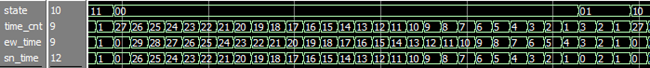
Figure 7.5.13.3 simulation diagram of traffic light control module
The code of nixie tube display module is as follows:
1   module seg_led(
2       input                  sys_clk     ,     //System clock
3       input                  sys_rst_n   ,     //System reset
4       input        [5:0]     ew_time     ,     //The value to be displayed by the nixie tube in the east-west direction
5       input        [5:0]     sn_time     ,     //The North-South nixie tube shall display the value
6       input                  en          ,     //Nixie tube enable signal
7       output  reg  [3:0]     sel         ,     //Nixie tube position selection signal
8       output  reg  [7:0]     seg_led           //Nixie tube segment selection signal, including decimal point
9   );
10
11  //parameter define
12  parameter  WIDTH = 50_000;                   //Counting depth of 1ms
13
14  //reg define
15  reg    [15:0]             cnt_1ms;           //Counter for counting 1ms
16  reg    [1:0]              cnt_state;         //Used to switch the nixie tube to be lit
17  reg    [3:0]              num;               //Data to be displayed by nixie tube
18
19  //wire define
20  wire   [3:0]              data_ew_0;         //Ten digits of nixie tube in east-west direction
21  wire   [3:0]              data_ew_1;         //East West nixie tube
22  wire   [3:0]              data_sn_0;         //Ten digits of North-South nixie tube
23  wire   [3:0]              data_sn_1;         //North South nixie tube
24
25  //*****************************************************
26  //**                    main code
27  //*****************************************************
28  assign  data_ew_0   = ew_time / 10;          //Take out the ten bits of East-West time data
29  assign  data_ew_1   = ew_time % 10;          //Take out the single bit of East-West time data
30  assign  data_sn_0   = sn_time / 10;          //Take out ten bits of North-South time data
31  assign  data_sn_1   = sn_time % 10;          //Take out the bits of North-South time data
32
33  //Count 1ms
34  always @ (posedge sys_clk or negedge sys_rst_n) begin
35      if (!sys_rst_n)
36          cnt_1ms <= 15'b0;
37      else if (cnt_1ms < WIDTH - 1'b1)
38          cnt_1ms <= cnt_1ms + 1'b1;
39      else
40          cnt_1ms <= 15'b0;
41  end
42
43  //Counter, used to switch the four states of nixie tube lighting
44  always @ (posedge sys_clk or negedge sys_rst_n) begin
45      if (!sys_rst_n)
46          cnt_state <= 2'd0;
47      else  if (cnt_1ms == WIDTH - 1'b1)
48          cnt_state <= cnt_state + 1'b1;
49      else
50          cnt_state <= cnt_state;
51  end
52
53  //First display ten digits of the nixie tube in the east-west direction, and then one digit. Then display ten digits of the North-South nixie tube, and then one digit
54  always @ (posedge sys_clk or negedge sys_rst_n) begin
55      if(!sys_rst_n) begin
56          sel  <= 4'b1111;
57          num  <= 4'b0;
58      end
59      else if(en) begin
60          case (cnt_state)
61              3'd0 : begin
62                  sel <= 4'b1110;              //Drive the ten bits of the digital tube in the east-west direction
63                  num <= data_ew_0;
64              end
65              3'd1 : begin
66                  sel <= 4'b1101;              //Drive a bit of the nixie tube in the east-west direction
67                  num <= data_ew_1;
68              end
69              3'd2 : begin
70                  sel <= 4'b1011;              //Drive the ten bits of the North-South nixie tube
71                  num  <= data_sn_0;
72              end
73              3'd3 : begin
74                  sel <= 4'b0111;              //Drive the bits of the North-South nixie tube
75                  num  <= data_sn_1 ;
76              end
77              default : begin
78                  sel <= 4'b1111;
79                  num <= 4'b0;
80              end
81          endcase
82      end
83      else  begin
84          sel <= 4'b1111;
85          num <= 4'b0;
86      end
87  end
88
89  //Segment selection signal corresponding to the value to be displayed by nixie tube
90  always @ (posedge sys_clk or negedge sys_rst_n) begin
91      if (!sys_rst_n)
92          seg_led <= 8'b0;
93      else begin
94          case (num)
95              4'd0 :     seg_led <= 8'b1100_0000;
96              4'd1 :     seg_led <= 8'b1111_1001;
97              4'd2 :     seg_led <= 8'b1010_0100;
98              4'd3 :     seg_led <= 8'b1011_0000;
99              4'd4 :     seg_led <= 8'b1001_1001;
100             4'd5 :     seg_led <= 8'b1001_0010;
101             4'd6 :     seg_led <= 8'b1000_0010;
102             4'd7 :     seg_led <= 8'b1111_1000;
103             4'd8 :     seg_led <= 8'b1000_0000;
104             4'd9 :     seg_led <= 8'b1001_0000;
105             default :  seg_led <= 8'b1100_0000;
106         endcase
107     end
108 end
109
110 endmodule
The dynamic nixie tube experiment shows that the refresh speed of nixie tube display is more appropriate in milliseconds. Therefore, in lines 33 to 41 of the code, a counter with a timing period of 1ms is generated. In order to generate the nixie tube bit selection control signal, a 2-bit counter CNT is set in the 16th line of the code_ state. The counter accumulates once every 1ms. It can count four hexadecimal numbers: 0, 1, 2 and 3. In lines 60 to 80 of the code, according to CNT_ The value of state drives different bit selection of nixie tube by assigning a value to sel register, and assigns the value to be displayed by the selected bit to num register. From line 94 to line 104 of the code, the corresponding segment selection control signal SEG can be generated according to the value of num_ led.
Figure 7.5.13.4 is the simulation diagram of nixie tube display module. At ew_time and Sn_ When the values of time are 24 and 21 respectively, during this 1s period, the nixie tube bit selection signal sel circularly switches the bit selection signal corresponding to the nixie tube, and then generates the corresponding segment selection signal SEG according to the num register_ led.
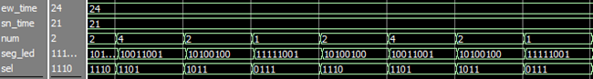
Figure 7.5.13.4 simulation diagram of nixie tube display module
The code of led lamp control module is as follows:
1   module led (
2       input              sys_clk   ,       //System clock
3       input              sys_rst_n ,       //System reset
4       input       [1:0]  state     ,       //Status of traffic lights
5       output reg  [5:0]  led               //Red, yellow and green LED light emitting enable
6   );
7
8   //parameter define
9   parameter  TWINKLE_CNT = 20_000_000;     //Count the number of times the yellow light flashes
10
11  //reg define
12  reg    [24:0]     cnt;                   //A counter that causes the yellow light to flash
13
14  //A counter with a counting time of 0.2s is used to flash the yellow light
15  always @(posedge sys_clk or negedge sys_rst_n)begin
16      if(!sys_rst_n)
17          cnt <= 25'b0;
18      else if (cnt < TWINKLE_CNT - 1'b1)
19          cnt <= cnt + 1'b1;
20      else
21          cnt <= 25'b0;
22  end
23
24  //In the four states of traffic lights, make the corresponding led lights shine
25  always @(posedge sys_clk or negedge sys_rst_n)begin
26      if(!sys_rst_n)
27          led <= 6'b100100;
28      else begin
29          case(state)
30              2'b00:led<=6'b100010;        //led registers are driven from high to low: East-West
31                                          //Red, green and yellow light, north-south red, green and yellow light
32              2'b01: begin
33                  led[5:1]<=5'b10000;
34                  if(cnt == TWINKLE_CNT - 1'b1)  //Count for 0.2 seconds to switch the on and off status of the yellow light once
35                                              //Produces a flickering effect
36                      led[0] <= ~led[0];
37                  else
38                      led[0] <= led[0];
39              end
40              2'b10:led<=6'b010100;
41              2'b11: begin
42                  led[5:4]<=2'b00;
43                  led[2:0]<=3'b100;
44                  if(cnt == TWINKLE_CNT - 1'b1)
45                      led[3] <= ~led[3];
46                  else
47                      led[3] <= led[3];
48              end
49              default:led<=6'b100100;
50          endcase
51      end
52  end
53
54  endmodule
In lines 25 to 48 of the code, drive the corresponding LED light according to the state value state. The output high 3-bit led[5:3] drives the red, yellow and green LED lights in the east-west direction from high to low, and the output low 3-bit led[2:0] drives the red, yellow and green LED lights in the north-south direction respectively.
During the yellow light on state, in order to produce the flashing effect, it is necessary to make it light up for a period of time and turn it off for another period of time, so as to cycle until the end of the yellow light on state. From line 14 to line 22 of the code, a counter with a counting cycle of 0.2s is generated, and the on-off state of the yellow light is switched once every 0.2s to achieve the flashing effect.
Figure 7.5.13.5 is the simulation diagram of led control module. It can be seen that when the value of state is 01 and 11 (there is a yellow light in the east-west direction or north-south direction), the value of led register is changing all the time.

Figure 7.5.13.5 led control module simulation diagram
The simulation file code is as follows:
1   `timescale 1ns/1ns
2   module tb_top_traffic     ;
3   reg            sys_clk    ;      //System clock
4   reg            sys_rst_n  ;      //System reset
5
6   wire  [3:0]    sel        ;      //Nixie tube position selection signal
7   wire  [7:0]    seg_led    ;      //Nixie tube segment selection signal
8   wire  [5:0]    led        ;      //led lamp control signal
9
10  initial begin
11  sys_clk        <= 1'b0;
12  sys_rst_n      <= 1'b0;
13  # 20 sys_rst_n <= 1'b1;
14  end
15
16  always # 10 sys_clk = ~sys_clk;  // Generate a clock with a frequency of 50Mhz
17
18  //Top level module of exemplary traffic light
19  top_traffic  u_top_traffic(
20  .sys_clk       (sys_clk   ),
21  .sys_rst_n     (sys_rst_n ),
22  .sel           (sel       ),
23  .seg_led       (seg_led   ),
24  .led           (led       )
25  );
26
27  endmodule
The files used in this simulation are on the data disk (disk A) of the navigator FPGA development board → 4_SourceCode→1_Verilog→top_traffic→digital_recognition.sim directory.
1.5 download verification
First, we connect the downloader to the JTAG interface on the navigator development board, and the other end of the Downloader is connected to the computer. Then plug the traffic light module into the board, finally connect the power supply of the development board and turn on the power switch, as shown in the figure below:
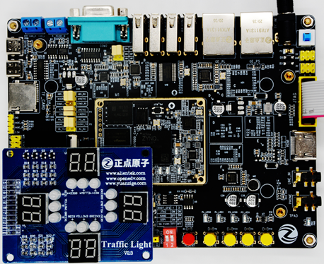
Figure 7.5.13.1 hardware connection diagram
After that, you can download the bit file. You can see that the traffic light module starts running, as shown below:
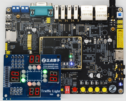
Figure 7.5.13.2 experimental phenomena of traffic lights