1. stm32 Running Horselight Experiment
a.GPIO
-
general purpose input output
-
Universal I/O port, which can be used as input or output, and GPIO port can be programmatically configured as input or output.
-
STM32FXXXIGT6 consists of nine groups of IO: PA~ PI, of which PA~ PH has 16 IOs per group and only PI0~PI11. 16*8+12=140, a total of 140 IO ports.
-
Most of the pins of STM32 can be reused as peripheral function pins, such as serial port, in addition to being used by GPIO. Save pin resources.
Eight working modes of b.GPIO
- Four input modes: input float, input pull-up, input drop-down, analog input
- Four output modes with drop-down: open-leak output (pull-down or pull-down), open-leak multiplexing, push-pull output, push-pull multiplexing
- Push-pull output can output high and low levels to connect digital devices
- Open-drain output can only output strong and low levels, which can be raised by external resistance. Output equals collector of tertiary tube
c.GPIO Register
4 32-bit Configuration Registers
GPIOx_MODER mode
GPIOx_OTYPER output type
GPIOx_OSPEEDR Output Speed
GPIOx_PUPDR pull-down
Two 32-bit data registers
GPIOx_IDR Input Data
GPIOx_ODR Output Data
A 32-position/reset register
GPIOx_BSRR Position/Reset
A 32-bit lock register
GPIOx_LCKR Configuration Lock
Two 32-bit multiplexed functional registers
GPIOx_ AFRL&GPIOx_ AFRH multiplexing function
- Each group of IO ports consists of 10 registers
- If configuring an IO port requires 2 bits, 32-bit registers configure a set of IO ports, 16 IO ports
- If only 1 bit is needed to configure an IO port, 16 bits high are reserved
1. Register Definition
F767: stm32f767xx.h
Find GPIO in the file to get:
typedef struct
{
  __IO uint32_t MODER;    /*!< GPIO port mode register,               Address offset: 0x00      */
  __IO uint32_t OTYPER;   /*!< GPIO port output type register,        Address offset: 0x04      */
  __IO uint32_t OSPEEDR;  /*!< GPIO port output speed register,       Address offset: 0x08      */
  __IO uint32_t PUPDR;    /*!< GPIO port pull-up/pull-down register,  Address offset: 0x0C      */
  __IO uint32_t IDR;      /*!< GPIO port input data register,         Address offset: 0x10      */
  __IO uint32_t ODR;      /*!< GPIO port output data register,        Address offset: 0x14      */
  __IO uint32_t BSRR;     /*!< GPIO port bit set/reset register,      Address offset: 0x18      */
  __IO uint32_t LCKR;     /*!< GPIO port configuration lock register, Address offset: 0x1C      */
  __IO uint32_t AFR[2];   /*!< GPIO alternate function registers,     Address offset: 0x20-0x24 */
} GPIO_TypeDef;
Find GPIO_again TypeDef found:
#define GPIOA               ((GPIO_TypeDef *) GPIOA_BASE)
#define GPIOB               ((GPIO_TypeDef *) GPIOB_BASE)
#define GPIOC               ((GPIO_TypeDef *) GPIOC_BASE)
#define GPIOD               ((GPIO_TypeDef *) GPIOD_BASE)
#define GPIOE               ((GPIO_TypeDef *) GPIOE_BASE)
#define GPIOF               ((GPIO_TypeDef *) GPIOF_BASE)
#define GPIOG               ((GPIO_TypeDef *) GPIOG_BASE)
#define GPIOH               ((GPIO_TypeDef *) GPIOH_BASE)
#define GPIOI               ((GPIO_TypeDef *) GPIOI_BASE)
#define GPIOJ               ((GPIO_TypeDef *) GPIOJ_BASE)
#define GPIOK               ((GPIO_TypeDef *) GPIOK_BASE)
You can see that GPIOA is a structure pointer that points to the base address.
GPIOA->ODR provides access to the ODR output registers of the GPIOA port.
2. Hardware connection for running lights
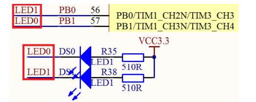
You can see that two LED lights, one end connected to LED 0, the other end connected to VCC through pull-up resistance. If PB0 outputs 0, then LED 1 is on.
GPIO output mode: Push-pull output (pull-up) that can output high and low levels
3. Configure register operation IO port steps
-
Initialize HAL library: HAL_Init();
-
Initialize the system clock:
stm32F767: Stm32_Clock_Init(431,25,2,9);
-
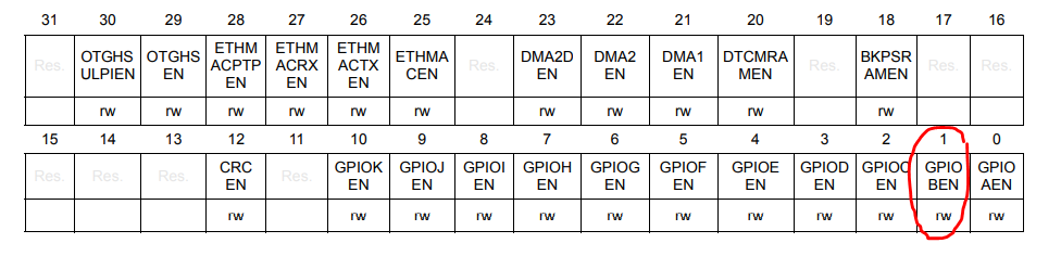
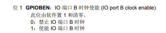
Enable IO port clock. Configure IO port clock enable register: RCC->AHB1ENR
RCC AHB1 Peripheral Clock Register (RCC_AHB1ENR)
-
Initialize IO port mode. Configure four configuration registers
GPIOx_MODER,GPIOx_OTYPER,GPIOx_OSPEEDR,GPIOx_PUPDR
-
Operate IO port to output high and low level
Configure Register GPIOX_ODR or GPIOx_BSRR
4. Handwritten Running Horselight
Stm32f7xx_inside HALLIB Hal. HAL_can be found in the C file The Init function, which is copied and pasted into the main() file, completes the initialization of the HAL library.
Sys inside SYSTEM. Stm32_found in C file Clock_ The Init function, which is copied and pasted into the main() file, completes the initialization of the system clock.
Stm32f7xx_inside HALLIB Hal. Search RCC_in C file TypeDef, you can see:
typedef struct
{
  __IO uint32_t CR;            /*!< RCC clock control register,                                  Address offset: 0x00 */
  __IO uint32_t PLLCFGR;       /*!< RCC PLL configuration register,                              Address offset: 0x04 */
  __IO uint32_t CFGR;          /*!< RCC clock configuration register,                            Address offset: 0x08 */
  __IO uint32_t CIR;           /*!< RCC clock interrupt register,                                Address offset: 0x0C */
  __IO uint32_t AHB1RSTR;      /*!< RCC AHB1 peripheral reset register,                          Address offset: 0x10 */
  __IO uint32_t AHB2RSTR;      /*!< RCC AHB2 peripheral reset register,                          Address offset: 0x14 */
  __IO uint32_t AHB3RSTR;      /*!< RCC AHB3 peripheral reset register,                          Address offset: 0x18 */
  uint32_t      RESERVED0;     /*!< Reserved, 0x1C                                                                    */
  __IO uint32_t APB1RSTR;      /*!< RCC APB1 peripheral reset register,                          Address offset: 0x20 */
  __IO uint32_t APB2RSTR;      /*!< RCC APB2 peripheral reset register,                          Address offset: 0x24 */
  uint32_t      RESERVED1[2];  /*!< Reserved, 0x28-0x2C                                                               */
  __IO uint32_t AHB1ENR;       /*!< RCC AHB1 peripheral clock register,                          Address offset: 0x30 */
  __IO uint32_t AHB2ENR;       /*!< RCC AHB2 peripheral clock register,                          Address offset: 0x34 */
  __IO uint32_t AHB3ENR;       /*!< RCC AHB3 peripheral clock register,                          Address offset: 0x38 */
  uint32_t      RESERVED2;     /*!< Reserved, 0x3C                                                                    */
  __IO uint32_t APB1ENR;       /*!< RCC APB1 peripheral clock enable register,                   Address offset: 0x40 */
  __IO uint32_t APB2ENR;       /*!< RCC APB2 peripheral clock enable register,                   Address offset: 0x44 */
  uint32_t      RESERVED3[2];  /*!< Reserved, 0x48-0x4C                                                               */
  __IO uint32_t AHB1LPENR;     /*!< RCC AHB1 peripheral clock enable in low power mode register, Address offset: 0x50 */
  __IO uint32_t AHB2LPENR;     /*!< RCC AHB2 peripheral clock enable in low power mode register, Address offset: 0x54 */
  __IO uint32_t AHB3LPENR;     /*!< RCC AHB3 peripheral clock enable in low power mode register, Address offset: 0x58 */
  uint32_t      RESERVED4;     /*!< Reserved, 0x5C                                                                    */
  __IO uint32_t APB1LPENR;     /*!< RCC APB1 peripheral clock enable in low power mode register, Address offset: 0x60 */
  __IO uint32_t APB2LPENR;     /*!< RCC APB2 peripheral clock enable in low power mode register, Address offset: 0x64 */
  uint32_t      RESERVED5[2];  /*!< Reserved, 0x68-0x6C                                                               */
  __IO uint32_t BDCR;          /*!< RCC Backup domain control register,                          Address offset: 0x70 */
  __IO uint32_t CSR;           /*!< RCC clock control & status register,                         Address offset: 0x74 */
  uint32_t      RESERVED6[2];  /*!< Reserved, 0x78-0x7C                                                               */
  __IO uint32_t SSCGR;         /*!< RCC spread spectrum clock generation register,               Address offset: 0x80 */
  __IO uint32_t PLLI2SCFGR;    /*!< RCC PLLI2S configuration register,                           Address offset: 0x84 */
  __IO uint32_t PLLSAICFGR;    /*!< RCC PLLSAI configuration register,                           Address offset: 0x88 */
  __IO uint32_t DCKCFGR1;      /*!< RCC Dedicated Clocks configuration register1,                 Address offset: 0x8C */
  __IO uint32_t DCKCFGR2;      /*!< RCC Dedicated Clocks configuration register 2,               Address offset: 0x90 */

} RCC_TypeDef;
AHB1ENR can be found. It is known from the registers that only bit 1 needs to be changed. Write RCC->AHB1ENR |=1< 1 in main (move one bit to the left, then either RCC->AHB1ENR can set bit 1 to 1) or RCC->AHB1ENR=0x02.
- Configure GPIO Port Mode Register GPIOx_MODER
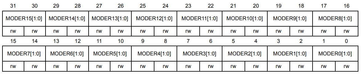
Since the port bits to be configured are 0 and 1, MODER1 and MODEER0 need to be configured. Because it is the push output, the last four bits 0101, or 5, are set, and the final MODER register is set to 0x05. Write GPIOB->MODER=0x05 in the main function.
- Next, configure the GPIO port output type register (GPIOx_OTYPER)
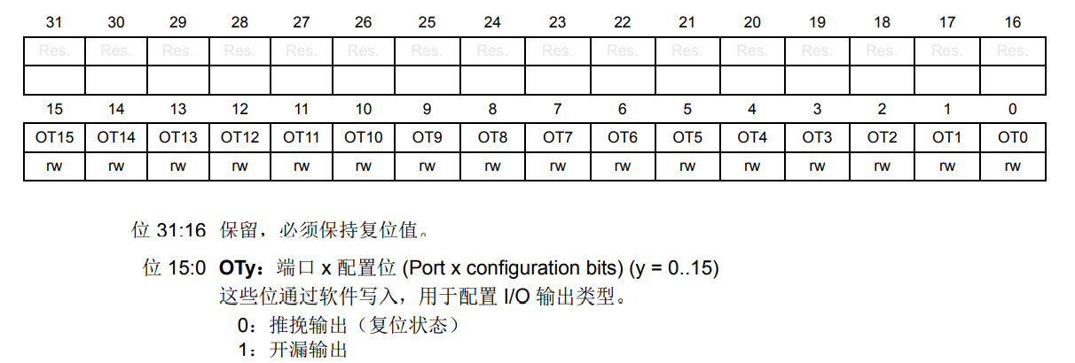
Ports 0 and 1 are both 0 because they are push outputs. Write GPIOB->OTYPER=0x00 in main function;
- Next, configure the GPIO port output speed register (GPIOx_OSPEEDR)
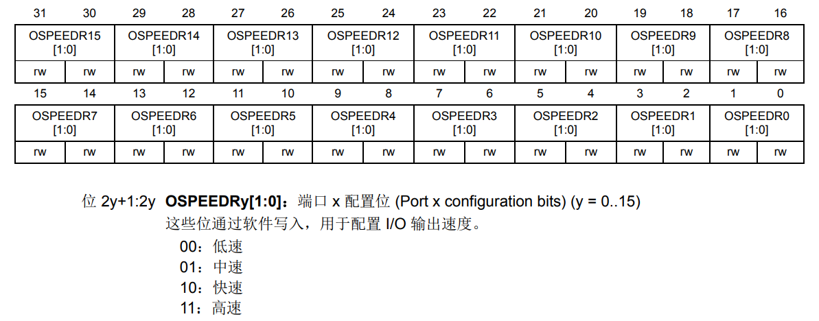
The last two bits of both ports are also 11 when set to high speed. Set this to GPIOB->OSPEEDR=0x0f; Although he has only written 8 digits, he actually has 32 digits in total. There are all zeros in front of him, which can be omitted from writing. To be more specific, he needs to fill 32 digits with all zeros.
- Configure GPIO port drop-down registers (GPIOx_PUPDR)
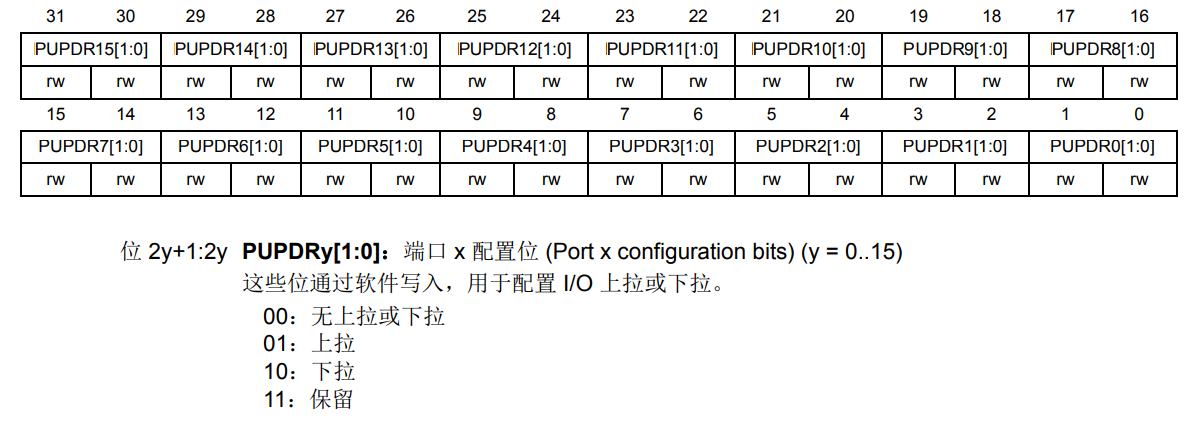
This is to be configured as a pull-up, so the last two ports are 0101, that is, to set GPIOB->PUPDR=0x05;
Then operate IO port, output high and low level, configure register GPIOX_ODR or GPIOx_BSRR.
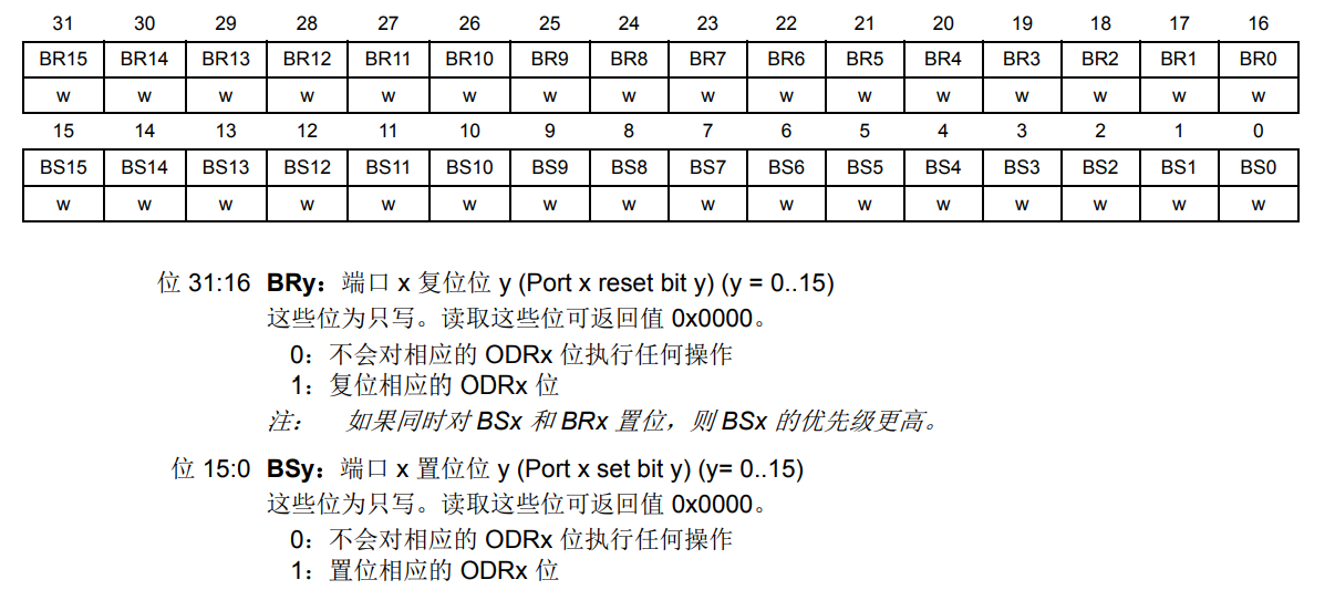
To configure port 1 and 0 to output high levels, BS1 and BS0 are required to be 1, and other bits remain constant to 0, that is, to configure to 0x03. If you configure port 1 and 0 to output low levels, that is, you need to reset BR1 and BR0 to 1, and the other bits remain constant to 0, that is, you need to configure to 0x00030000. Write code GPIOB->BSRR=0x00000003;// 1, GPIOB->BSRR=0x00030000;// 0.
Then, because the on and off intervals are too short, a delay function is needed. In SYSTEM-delay. You can find delay in the C file. H, then enter delay.h header file, you can see void delay_init(u8 SYSCLK);void delay_ms(u16 nms);void delay_us(u32 nus); Three functions. Initialize delay_first with delay Init (216); 216 is the system clock of stm32f767. Then you can call delay_ms(500);
The final code is:
#include "sys.h"
#include "delay.h"
#include "usart.h"

int main(void)
{
	HAL_Init();
	Stm32_Clock_Init(431,25,2,9);
	delay_init(216);
	RCC->AHB1ENR |= 1<<1;
	GPIOB->MODER=0x05;
	GPIOB->OTYPER=0x00;
	GPIOB->OSPEEDR=0x0f;
	GPIOB->PUPDR=0x05;
	while(1)
	{
		GPIOB->BSRR=0x00000003;//1
		delay_ms(500);
		GPIOB->BSRR=0x00030000;//0
		delay_ms(500);
	}
}
5. Use the HAL Library
Advantages: Easy to migrate in various stm32 platforms.
HAL library solves the problem of program migration very well. The standard libraries of different types of stm32 chips are different. For example, programs developed on F4 cannot be used in F3. Using HAL library, programs can basically copy and paste completely as long as they use the same peripherals.
Stm32f7xx_can be found under the HALLIB folder Hal_ Gpio. C file, then find stm32f7xx_hal_gpio.h file, you can see several functions inside:
/* Initialization and de-initialization functions *****************************/
void  HAL_GPIO_Init(GPIO_TypeDef  *GPIOx, GPIO_InitTypeDef *GPIO_Init);//Initialization function
void  HAL_GPIO_DeInit(GPIO_TypeDef  *GPIOx, uint32_t GPIO_Pin);
/**
/* IO operation functions *****************************************************/
GPIO_PinState HAL_GPIO_ReadPin(GPIO_TypeDef* GPIOx, uint16_t GPIO_Pin);//Read Input Level Function
void HAL_GPIO_WritePin(GPIO_TypeDef* GPIOx, uint16_t GPIO_Pin, GPIO_PinState PinState);//Set Output Level Function
void HAL_GPIO_TogglePin(GPIO_TypeDef* GPIOx, uint16_t GPIO_Pin);//Level flip function
HAL_StatusTypeDef HAL_GPIO_LockPin(GPIO_TypeDef* GPIOx, uint16_t GPIO_Pin);//Pin Level Lock Function
void HAL_GPIO_EXTI_IRQHandler(uint16_t GPIO_Pin);//External interrupt function
void HAL_GPIO_EXTI_Callback(uint16_t GPIO_Pin);
-
void HAL_GPIO_Init(GPIO_TypeDef *GPIOx, GPIO_InitTypeDef *GPIO_Init);
Initializes the working mode, output type, speed, and pull-down mode of one or more IO ports (same group). This is the four configuration registers for a set of IO ports. MODER, OSPEEDR, OTYPER, PUPDR. At stm32f7xx_hal_gpio.h Find HAL_GPIO_Init function, then go to definition, you can find HAL_GPIO_Init implementation, you can see that his main operations are MODER, OSPEEDR, OTYPER, PUPDR registers.
    GPIO_Initure.Pin=GPIO_PIN_0|GPIO_PIN_1; //PB1,0
	GPIO_Initure.Mode=GPIO_MODE_OUTPUT_PP;  //push-pull
	GPIO_Initure.Pull=GPIO_PULLUP;          //Pull Up
	GPIO_Initure.Speed=GPIO_SPEED_HIGH;     //high speed
	HAL_GPIO_Init(GPIOB,&GPIO_Initure);     //One parameter is to set which group, the other is to initialize the structure
-
GPIO_PinState HAL_GPIO_ReadPin(GPIO_TypeDef* GPIOx, uint16_t GPIO_Pin);
Read the input level of a GPIO, the actual operation is GPIOx_IDR Register
-
void HAL_GPIO_WritePin(GPIO_TypeDef* GPIOx, uint16_t GPIO_Pin, GPIO_PinState PinState);
Set pin output level
HAL_GPIO_WritePin(GPIOB,GPIO_PIN_0,GPIO_PIN_SET);	//PB0 Position 1
HAL_GPIO_WritePin(GPIOB,GPIO_PIN_1,GPIO_PIN_SET);	//PB1 Position 1
-
void HAL_GPIO_TogglePin(GPIO_TypeDef* GPIOx, uint16_t GPIO_Pin);
Output Level Flip Function
6. Configure HAL library operation IO port steps
-
Initialize HAL Library HAL_Init()
-
Initialize system clock Stm32_Clock_Init()
-
Enable IO Port Clock_ HAL_RCC_GPIOB_CLK_ENABLE(); Configure IO port clock enable register: RCC->AHB1ENR
In HALLIB file-stm32f7xx_ Hal_ Rcc. You can find it in the ex.h file: u HAL_RCC_GPIOA_CLK_ENABLE(), this function actually operates on RCC->AHB1ENR
#define __HAL_RCC_GPIOA_CLK_ENABLE() do { \ __IO uint32_t tmpreg; \ SET_BIT(RCC->AHB1ENR, RCC_AHB1ENR_GPIOAEN);\ /* Delay after an RCC peripheral clock enabling */ \ tmpreg = READ_BIT(RCC->AHB1ENR, RCC_AHB1ENR_GPIOAEN);\ UNUSED(tmpreg); \ } while(0) -
Initialize IO Port Mode HAL_GPIO_Init(); Operation register: GPIOx_MODER OTYPER OSPEEDR PUPDR
At stm32f7xx_hal_gpio.c File found HAL_GPIO_Init(), and then observe its parameter GPIO_TypeDef *GPIOx and GPIO_InitTypeDef *GPIO_Init, now to understand what GPIOx is, find the operation on GPIOx in the code below. assert_param(IS_GPIO_ALL_INSTANCE(GPIOx)); Then select IS_ GPIO_ ALL_ INSTANCE click go to definition to find:
#define IS_GPIO_ALL_INSTANCE(__INSTANCE__) (((__INSTANCE__) == GPIOA) || \
                                        ((__INSTANCE__) == GPIOB) || \
                                        ((__INSTANCE__) == GPIOC) || \
                                        ((__INSTANCE__) == GPIOD) || \
                                        ((__INSTANCE__) == GPIOE) || \
                                        ((__INSTANCE__) == GPIOF) || \
                                        ((__INSTANCE__) == GPIOG) || \
                                        ((__INSTANCE__) == GPIOH) || \
                                        ((__INSTANCE__) == GPIOI) || \
                                        ((__INSTANCE__) == GPIOJ) || \
                                        ((__INSTANCE__) == GPIOK))
You can see that this function operates on something like GPIOA, GPIOB, so GPIO_ The TypeDef *GPIOx parameter is set to GPIOB.
Here's how to set GPIO_InitTypeDef *GPIO_Init parameter, you can see that this is the structure type.
typedef struct
{
  uint32_t Pin;       /*!< Specifies the GPIO pins to be configured.
                           This parameter can be any value of @ref GPIO_pins_define */

  uint32_t Mode;      /*!< Specifies the operating mode for the selected pins.
                           This parameter can be a value of @ref GPIO_mode_define */

  uint32_t Pull;      /*!< Specifies the Pull-up or Pull-Down activation for the selected pins.
                           This parameter can be a value of @ref GPIO_pull_define */

  uint32_t Speed;     /*!< Specifies the speed for the selected pins.
                           This parameter can be a value of @ref GPIO_speed_define */

  uint32_t Alternate;  /*!< Peripheral to be connected to the selected pins.
                            This parameter can be a value of @ref GPIO_Alternate_function_selection */
}GPIO_InitTypeDef;
Then set up this structure member, first decide how to set MODE, find out
assert_param(IS_GPIO_PIN(GPIO_Init->Pin));
assert_param(IS_GPIO_MODE(GPIO_Init->Mode));
assert_param(IS_GPIO_PULL(GPIO_Init->Pull));Go to define IS_GPIO_MODE, you can see that the model can be set to many types, we set it here to push-pull output, so set it to GPIO_MODE_OUTPUT_PP.
#define IS_GPIO_PIN_ACTION(ACTION) (((ACTION) == GPIO_PIN_RESET) || ((ACTION) == GPIO_PIN_SET))
#define IS_GPIO_PIN(PIN)           (((PIN) & GPIO_PIN_MASK ) != (uint32_t)0x00)
#define IS_GPIO_MODE(MODE) (((MODE) == GPIO_MODE_INPUT)              ||\
                            ((MODE) == GPIO_MODE_OUTPUT_PP)          ||\
                            ((MODE) == GPIO_MODE_OUTPUT_OD)          ||\
                            ((MODE) == GPIO_MODE_AF_PP)              ||\
                            ((MODE) == GPIO_MODE_AF_OD)              ||\
                            ((MODE) == GPIO_MODE_IT_RISING)          ||\
                            ((MODE) == GPIO_MODE_IT_FALLING)         ||\
                            ((MODE) == GPIO_MODE_IT_RISING_FALLING)  ||\
                            ((MODE) == GPIO_MODE_EVT_RISING)         ||\
                            ((MODE) == GPIO_MODE_EVT_FALLING)        ||\
                            ((MODE) == GPIO_MODE_EVT_RISING_FALLING) ||\
                            ((MODE) == GPIO_MODE_ANALOG))
#define IS_GPIO_SPEED(SPEED) (((SPEED) == GPIO_SPEED_LOW)  || ((SPEED) == GPIO_SPEED_MEDIUM) || \
                              ((SPEED) == GPIO_SPEED_FAST) || ((SPEED) == GPIO_SPEED_HIGH))
#define IS_GPIO_PULL(PULL) (((PULL) == GPIO_NOPULL) || ((PULL) == GPIO_PULLUP) || \
                            ((PULL) == GPIO_PULLDOWN))
Then find the pin settings and find a GPIO_inside PIN_ MASK, GPIO_selected PIN_ MASK click go to definition. You can find the following code, so this can be set to GPIO_PIN_0.
#define GPIO_PIN_0                 ((uint16_t)0x0001U)  /* Pin 0 selected    */
#define GPIO_PIN_1                 ((uint16_t)0x0002U)  /* Pin 1 selected    */
#define GPIO_PIN_2                 ((uint16_t)0x0004U)  /* Pin 2 selected    */
#define GPIO_PIN_3                 ((uint16_t)0x0008U)  /* Pin 3 selected    */
#define GPIO_PIN_4                 ((uint16_t)0x0010U)  /* Pin 4 selected    */
#define GPIO_PIN_5                 ((uint16_t)0x0020U)  /* Pin 5 selected    */
#define GPIO_PIN_6                 ((uint16_t)0x0040U)  /* Pin 6 selected    */
#define GPIO_PIN_7                 ((uint16_t)0x0080U)  /* Pin 7 selected    */
#define GPIO_PIN_8                 ((uint16_t)0x0100U)  /* Pin 8 selected    */
#define GPIO_PIN_9                 ((uint16_t)0x0200U)  /* Pin 9 selected    */
#define GPIO_PIN_10                ((uint16_t)0x0400U)  /* Pin 10 selected   */
#define GPIO_PIN_11                ((uint16_t)0x0800U)  /* Pin 11 selected   */
#define GPIO_PIN_12                ((uint16_t)0x1000U)  /* Pin 12 selected   */
#define GPIO_PIN_13                ((uint16_t)0x2000U)  /* Pin 13 selected   */
#define GPIO_PIN_14                ((uint16_t)0x4000U)  /* Pin 14 selected   */
#define GPIO_PIN_15                ((uint16_t)0x8000U)  /* Pin 15 selected   */
#define GPIO_PIN_All               ((uint16_t)0xFFFFU)  /* All pins selected */

#define GPIO_PIN_MASK              ((uint32_t)0x0000FFFFU) /* PIN mask for assert test */
Similarly set pull and speed
-
Operate IO port, output high and low level HAL_GPIO_WritePin(); Configure Register GPIOX_ODR or GPIOx_BSRR
Finally, in main:
int main()
{
	GPIO_InitTypeDef GPIO_InitStructure;
	HAL_Init();
	delay_init(216);
	Stm32_Clock_Init(431,25,2,9);
	__HAL_RCC_GPIOB_CLK_ENABLE();//Enable PB Clock
	GPIO_InitStructure.Mode=GPIO_MODE_OUTPUT_PP;//push-pull
	GPIO_InitStructure.Pin=GPIO_PIN_0 | GPIO_PIN_1;
	GPIO_InitStructure.Pull=GPIO_PULLUP;//Pull Up
	GPIO_InitStructure.Speed=GPIO_SPEED_FREQ_VERY_HIGH;//high speed

	HAL_GPIO_Init(GPIOB,&GPIO_InitStructure);
	while(1){
		HAL_GPIO_WritePin(GPIOB,GPIO_PIN_0,GPIO_PIN_RESET);//PB0=0
		HAL_GPIO_WritePin(GPIOB,GPIO_PIN_1,GPIO_PIN_RESET);//PB1=0
		delay_ms(500);
		HAL_GPIO_WritePin(GPIOB,GPIO_PIN_0,GPIO_PIN_RESET);//PB0=1
		HAL_GPIO_WritePin(GPIOB,GPIO_PIN_1,GPIO_PIN_RESET);//PB1=1
		delay_ms(500);

	}

}
2. stm32 key experiment
1. Circuit connection diagram
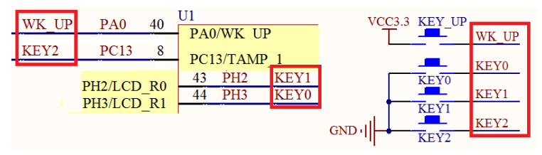
As you can see from the diagram, KEY0, KEY1, KEY2 need to be set to pull up, so if the keys KEY0, KEY1, KEY2 are pressed, then the low level signal will be obtained, if KEY0, KEY1, KEY2 are not pressed, it will be the high level signal. WK_UP set to drop down, KEY_ If UP is pressed, a high level signal will be detected, and if it is not pressed, a low level signal will be detected. KEY0->PH3 pull-up input, KEY1->PH2 pull-up input, KEY2->PC13 pull-up input, WK_UP->PA0 drop-down input.
2. Steps
1. Enable keys to correspond to IO port clock
__HAL_RCC_GPIOx_CLK_ENABLE();
From the circuit connection diagram, it can be found that the A, C, H ports are involved:
	__HAL_RCC_GPIOA_CLK_ENABLE();           //Turn on GPIOA clock
    __HAL_RCC_GPIOC_CLK_ENABLE();           //Turn on GPIOC clock
    __HAL_RCC_GPIOH_CLK_ENABLE();           //Turn on GPIOH clock
2. Initialize IO mode: pull-up/drop-down input
HAL_GPIO_Init
Based on KEY0->PH3 pull-up input, KEY1->PH2 pull-up input, KEY2->PC13 pull-up input, WK_ UP->PA0 drop-down input.
 	GPIO_InitTypeDef GPIO_Initure;
	GPIO_Initure.Pin=GPIO_PIN_0;            //PA0
    GPIO_Initure.Mode=GPIO_MODE_INPUT;      //input
    GPIO_Initure.Pull=GPIO_PULLDOWN;        //drop-down
    GPIO_Initure.Speed=GPIO_SPEED_HIGH;     //high speed
    HAL_GPIO_Init(GPIOA,&GPIO_Initure);

    GPIO_Initure.Pin=GPIO_PIN_13;           //PC13
    GPIO_Initure.Mode=GPIO_MODE_INPUT;      //input
    GPIO_Initure.Pull=GPIO_PULLUP;          //Pull Up
    GPIO_Initure.Speed=GPIO_SPEED_HIGH;     //high speed
    HAL_GPIO_Init(GPIOC,&GPIO_Initure);

    GPIO_Initure.Pin=GPIO_PIN_2|GPIO_PIN_3; //PH2,3
    HAL_GPIO_Init(GPIOH,&GPIO_Initure);
3. Scan IO port level (library function/register)
HAL library function: GPIO_PinState HAL_GPIO_ReadPin();
Register: GPIOx_IDR
4. Write key scan logic
Keys support continuous press, for example, remote control, keep pressing, change stations. If continuous press is not supported, it means that the remote control will change stations next time, and if it keeps pressing after, it will not change stations. If continuous press is not supported, a variable is needed to record the last state. If it was not pressed last time, this time a press is detected, indicating that the key is pressed. If the last press is detected, then this press does not count, that is, the key is pressed, not released, but only once.
Key scan supports the idea of continuous press:
u8 KEY_Scan(void){
	if(KEY Press)
	{
		delay_ms(10);//Delayed Anti-shake
		if(KEY Do press){
			return KEY_Value;
		}
		return Invalid value;
	}
}
What is the return value after each call to the getValue function
int getValue()
{
	static int flag = 0;
	flag++;
	return flag;
}
Each call, returns 1 for the first time and 2 for the second time... Because the static variable exists, the static-modified variable is initialized only once and keeps the closest value. Even if the function that created it has ended, the variable will not be released. The next call is at the same address, so the value inside is the last. Variables defined by static have a memory effect. So the idea of press-and-press is not supported: note key_up must record the last status.
u8 KEY_SCAN(void)
{
    static u8 key_up = 1;//Not pressed
    if(key_up && KEY Press)//Last release, this time press
    {
        delay_ms(10);
        key_up=0;
        if(KEY Do press){
            return KEY_VALUE;
        }
    }
    else if(KEY Not pressed)
        key_up=1;
}
3. Code
//Key Initialization Function
void KEY_Init(void)
{
    GPIO_InitTypeDef GPIO_Initure;

    __HAL_RCC_GPIOA_CLK_ENABLE();           //Turn on GPIOA clock
    __HAL_RCC_GPIOC_CLK_ENABLE();           //Turn on GPIOC clock
    __HAL_RCC_GPIOH_CLK_ENABLE();           //Turn on GPIOH clock

    GPIO_Initure.Pin=GPIO_PIN_0;            //PA0
    GPIO_Initure.Mode=GPIO_MODE_INPUT;      //input
    GPIO_Initure.Pull=GPIO_PULLDOWN;        //drop-down
    GPIO_Initure.Speed=GPIO_SPEED_HIGH;     //high speed
    HAL_GPIO_Init(GPIOA,&GPIO_Initure);

    GPIO_Initure.Pin=GPIO_PIN_13;           //PC13
    GPIO_Initure.Mode=GPIO_MODE_INPUT;      //input
    GPIO_Initure.Pull=GPIO_PULLUP;          //Pull Up
    GPIO_Initure.Speed=GPIO_SPEED_HIGH;     //high speed
    HAL_GPIO_Init(GPIOC,&GPIO_Initure);

    GPIO_Initure.Pin=GPIO_PIN_2|GPIO_PIN_3; //PH2,3
    HAL_GPIO_Init(GPIOH,&GPIO_Initure);
}

//Key Processing Function
//Return key value
//mode:0, continuous press is not supported; 1, Support continuous press;
//0, no key press
//1, WKUP press WK_UP
//Notice that this function has response priority, KEY0>KEY1>KEY2>WK_ UP!!
u8 KEY_Scan(u8 mode)
{
    static u8 key_up=1;     //Key release sign
    if(mode==1)key_up=1;    //Support Limited Press
    if(key_up&&(KEY0==0||KEY1==0||KEY2==0||WK_UP==1))
    {
        delay_ms(10);
        key_up=0;
        if(KEY0==0)       return KEY0_PRES;
        else if(KEY1==0)  return KEY1_PRES;
        else if(KEY2==0)  return KEY2_PRES;
        else if(WK_UP==1) return WKUP_PRES;
    }else if(KEY0==1&&KEY1==1&&KEY2==1&&WK_UP==0)key_up=1;
    return 0;   //No key press
}

int main(void)
{
   	u8 key;
	u8 led0sta=1,led1sta=1;		    //LED 0, current status of LED 1
    Cache_Enable();                 //Open L1-Cache
    HAL_Init();				        //Initialize HAL Library
    Stm32_Clock_Init(432,25,2,9);   //Set clock, 216Mhz
    delay_init(216);                //Delayed Initialization
	uart_init(115200);		        //Serial port initialization
    LED_Init();                     //Initialize LED
    KEY_Init();                     //Key Initialization
    while(1