1, Composition of instructions
General format of instruction:
	Operation code( opc)   Destination operand     Source operand
 Operand type:
	1.Immediate operand source
	2.Register operand source and destination
	3.Memory operand	Source and target
2, Addressing mode
The so-called addressing mode refers to the method of obtaining the address of the operand
1. Find the address of the operand
2. Find the address of the next instruction to be executed
Immediate addressing
	The source operand is an immediate number, which is stored in the code segment as part of the instruction
	For example: MOV AX,3102H

Direct addressing
	For example: MOV AX,[3102H]
	[]Inside is the offset address. The segment base address defaults to the data segment, but can be reset
	For example: MOV AX,ES:[3102H]

Register addressing
	For example: MOV AX,BX
	This method does not need to access memory and executes faster.
register indirect addressing
	For example: MOV AX,[BX]
Register Relative Addressing
	For example: MOV AL,DATA[SI]

Base address - indexed addressing
	For example: MOV AL,[BX][SI]
Base index relative addressing
	For example: MOV AL,5[BX][SI]
		  MOV AL,TABLE[BX][SI]
Implicit addressing
	: MUL BL
	The function is to AL And BL Multiply AX
3, Instruction system
1. Data transfer instruction
1,MOV
1.Register and segment register and memory
2.Count to memory register immediately
3.Memory and segment register
 Cannot be a memory operand and a segment register at the same time
2. Stack operation instruction
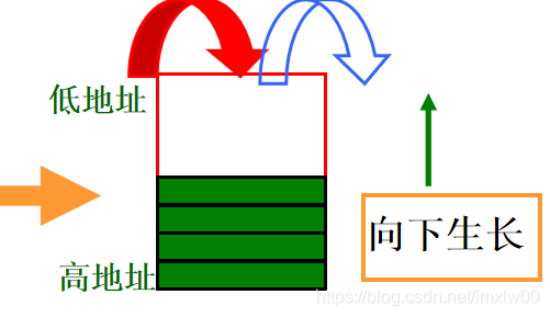
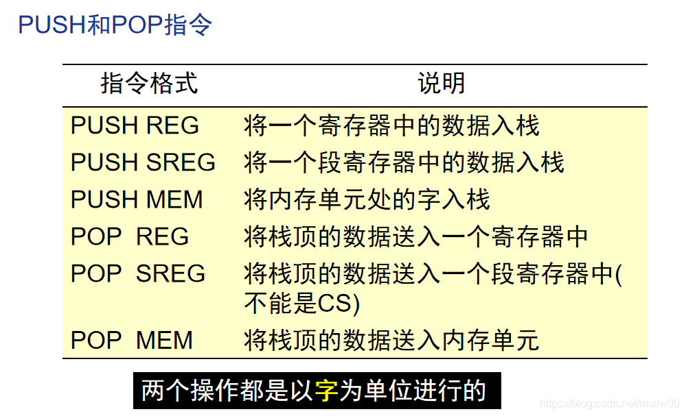
Storage direction: increase from high address to low address
3. Exchange operation instructions
XCHG OPRD1,OPRD2
 Requirements: it cannot be a memory at the same time, there cannot be segment register operands, and the word length must be equal
2. Table lookup conversion instruction
XLAT
Set the offset address to BX+AL The content of the unit is sent to AL in
2. Input / output instruction
Port oriented read and write instructions.
The input instruction IN is used to read data from the I/O port to the accumulators AX and AL,
The output instruction is used to write the contents of accumulator AX and AL to the I/O port
There are two ways to represent the port address
1. Immediate 2, DX
For example: IN AL,DX
IN AX,3FH
OUT 43H,AL
OUT DX,33FH
3. Fetch offset address instruction
Instruction format: LEA reg16, mem
Send the 16 bit offset address of memory mem to the register
The source operand must be a memory operand and the destination operand must be a 16 bit general purpose register
3. Arithmetic operation instruction
1. Addition instruction
1.ADD OPRD1,OPRD2
The source operand is added to the destination operand, and the result is sent to the destination address.
Requirements and MOV The instructions are the same. DS Cannot be an operand.
ADD It affects all 6 status bits
2.ADC
CF The carry status register is also involved in the operation
3.INC
 Unable to deposit segment, unable to count immediately
2. Subtraction instruction
 1.SUB
 2.SBB There is a borrow space
 3.DEC
Compare instruction CMP
     CMP OPRD1,OPRD2       ;OPRD1-OPRD2,The result is not returned OPRD1
Judge the relationship between two operands through the status bit
1,ZF=1,The operands are equal
2,For unsigned numbers, if CF=0,The subtracted is greater than the subtracted
3. Multiply MUL instruction
	Implicit addressing is adopted, and the implicit destination operand is AX,DX
	For 8-digit multiplication, the product is placed in AX
	For 16 bit multiplication, the high 16 of the product is placed in DX,Put it low AX
4. Division instruction DIV
The length of the divided number must be twice the length of the divided number
 The eight quotients obtained are placed in AL,Put the remainder in AH
 The 16 quotients obtained are placed in AX,Put the remainder in DX
4. Logical operation instruction
AND zero
OR set one
The NOT single operand instruction reverses the OPRD bit by bit and returns the operand
XOR XOR bitwise XOR and returns the result
Always use this feature to clear the register
XOR AX,AX
2. Shift command SAL SAR SLL SLR
Unsigned number corresponding to logical shift
Arithmetic shift for signed numbers
TEST is similar to AND, but does not return the result, only affects the flag bit
3. String operation instruction
Characteristics of transmitting operation instructions
  1.The source string is a data segment by default, and the segment base address is DS Medium, but segment reset is allowed. For offset address SI Register specifies that the target string pointer is DS:SI
  2.The source string defaults to ES Additional segment, segment reset is not allowed. For offset address DI Register specifies that the target string pointer is ES:DIt
  3.String length value placed in CX Register.
  4.The string operation instruction itself can realize the automatic modification of the address pointer. After operating on each byte or word,
    SI and DI The contents of the register will be automatically modified, and the direction and flag bit will be modified DF Related to the status of. DF=0,Direction is address increment
  5.Use a duplicate prefix before a string operation instruction. If a duplicate prefix is used, after each string operation, cx Automatically minus one.
To sum up, before using the string operation instruction: first set the source string pointer (DS,SI), target string pointer (ES,DI), repetition number CX and operation direction DF.
Repeat operation prefix
   REP: Repeat the prefix unconditionally until cx=0
   REPE/REPZ equal/Repeat when the result is zero,ZF=1,And CX!=0 Time repetition
   REPNE/REPNZ equal/Repeat when the result is not zero,ZF=0,And CX!=0 Time repetition
String operation instruction
1. Serial transmission instruction
movs oprd1,oprd2
movsb: movs byte ptr es:[edi],byte ptr ds:[esi]
movsw: movs word ptr es:[edi],word ptr ds:[esi]
movsd: movs dword ptr es:[edi],dword ptr ds:[esi]
2. Serial transmission instruction
	cmps oprd1,oprd2
	cmpsb
	cmpsw
    The prefix is usually repeated with the condition REPE or REPNE Used in conjunction to check whether a string is equal
3. Serial scan command
	SCAS OPRD           ;OPRD Is the target string
	SCASB
	SCASW
	use AL/AX The value of is compared with the byte in the target string. The comparison result does not change the target operand, but only affects the flag bit.
String loading instruction LODS LODSB LODSW
String storage instruction STOS STOSB STOSW
Program control instruction
Unconditional branch instruction JMP
	1.Intra segment direct transfer
	JMP LABEL
	2.Intra segment indirect transfer
	JMP BX
	JMP WORD PTR[BX+DI]
	Equal to pair IP register assignment
	3.Direct transfer between segments
	JMP FAR LABEL
	JMP 8000H:1200H
Conditional transition instruction JCC
name								Transfer conditions
JC                                  cf=1
JNC									cf=0
JCXZ         						cx=0
JE/JZ                               zf=1
JNE/JNZ                             zf=0
JG/JNLE
JGE/JNL
JL/JNGE
JLE/JNG
Cycle control command
Does not affect the flag bit
1.LOOP LABEL
amount to
DEC CX
JNZ NEXT
2.LOOPZ/LOOPE
 The condition for continuing the cycle is CX!=0&&ZF==1
Procedure call and return
CALL instruction
The format is similar to JMP
RET return instruction
interrupt
Purpose: 1 Users can call special subroutines provided by the operating system through interrupt instructions, such as console input and output, file system, software and hardware resource management and communication.
2. When debugging the program, run it step by step and set the breakpoint
3,BIOS
INT n
IRET
Differences between INT and CALL
1.INT needs to stack FLAGS, CALL doesn't
2. If, TF and call are not affected by INT
3. The interrupt service program entry address is placed in a fixed position in the memory so that it can be found through the interrupt vector code, and the CALL instruction can arbitrarily specify the storage location of the program entry address.