catalogue
background
When using STM32 for project development, two channels of input acquisition are required. At the beginning, using different timers for acquisition can meet the requirements. However, when a new demand comes, multiple PWM outputs and two input captures need to be added. During resource allocation, it is found that if a timer can collect four channels at the same time, if the new demand comes again, there can also be margin to realize PWM outputs of different frequencies (the same timer frequency can be used for input capture, but the PWM output may be different for the scene), Therefore, it is a very effective function to realize multi-channel acquisition of the same timer.
Implementation method
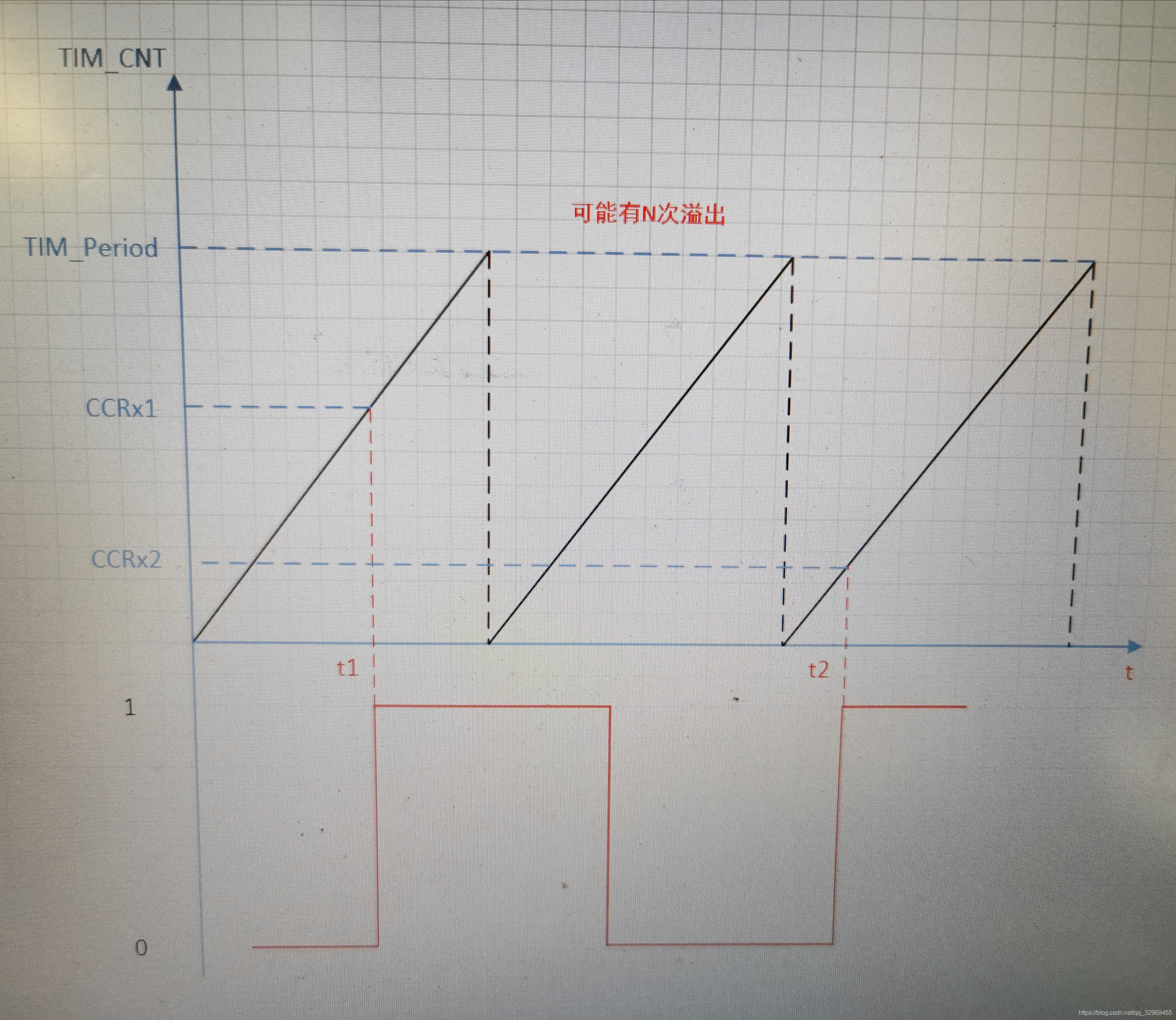
In the input capture mode, when the corresponding edge on the ICx signal is detected, the current value of the counter is locked into the capture / comparison register (TIMx_CCRx). If we record the timx at this time after the first edge trigger_ Ccrx value, marked as CCRx_FIRST, record timx after the next edge trigger_ Ccrx value, marked as CCRx_SECOND, calculate the difference between the two values to obtain the frequency of the acquisition waveform. However, here we need to consider a situation that occurs frequently: the counter CNT value overflows. If you just subtract at this time, you can't. How to solve it? We introduce the familiar timer update interrupt. Each overflow will trigger an update interrupt. We record several update interrupts from the first edge trigger to the second edge trigger, which are recorded as UPDATE_CNT, and then the capture count value can be calculated by the following formula:
CAPTURE_COUNT = CCRx_SECOND - CCRx_FIRST + PERIOD_COUNT*UPDATE_CNT;
Including: CAPTURE_COUNT is the capture count value, PERIOD_COUNT sets the cycle value for the capture timer, which is generally set to 0xFFFF as the capture input.
After obtaining the capture count value, we can calculate the cycle, frequency and other parameters (this method cannot calculate the duty cycle). Although we have completed one capture, we still need to prepare for the next capture. The work to be done is: 1 Empty UPDATE_CNT value 2 Set ccrx_ The value of second is used as the value obtained from the first acquisition, so that continuous acquisition can be achieved without losing the waveform
So far, we can support the multi-channel capture function. The above implementation method does not describe the input capture configuration channel of the timer. You can refer to other relevant materials in this regard.
Pictures from blogs https://blog.csdn.net/qq_32969455/article/details/107055592
development environment
| master control | STM32F103VET6 |
| IDE | KEIL MDK528 |
Although the development environment used in this code is pointed out here, for this article, it is not closely related to the chip model, and the ideas of other chip development methods are similar.
code implementation
/**
******************************************************************************
* @file tim.c
* @brief This file provides code for the configuration
* of the TIM instances.
******************************************************************************
* @attention
*
* <h2><center>© Copyright (c) 2021 STMicroelectronics.
* All rights reserved.</center></h2>
*
* This software component is licensed by ST under BSD 3-Clause license,
* the "License"; You may not use this file except in compliance with the
* License. You may obtain a copy of the License at:
* opensource.org/licenses/BSD-3-Clause
*
******************************************************************************
*/
/* Includes ------------------------------------------------------------------*/
#include "tim.h"
/* USER CODE BEGIN 0 */
/* USER CODE END 0 */
TIM_HandleTypeDef htim2;
TIM_HandleTypeDef htim3;
TIM_HandleTypeDef htim4;
/* IC capture edge define*/
#define IC_RISE_EDGE_FIRST 0
#define IC_RISE_EDGE_SECOND 1
/* IC capture Parameters define*/
#define TIM_ICOF_MAX 0x32
#define TIM_IC_MAX (4)
typedef struct tim_ic_info_st
{
uint8_t update_cnt;
uint8_t edge_seq;
uint32_t cap_val_last;
uint32_t cap_val_cur;
uint32_t cap_sum;
float freq;
}tim_ic_info_t;
tim_ic_info_t tim_ic_info[TIM_IC_MAX] = {0};
/* TIM2 init function */
void MX_TIM2_Init(void)
{
/* USER CODE BEGIN TIM2_Init 0 */
/* USER CODE END TIM2_Init 0 */
TIM_ClockConfigTypeDef sClockSourceConfig = {0};
TIM_MasterConfigTypeDef sMasterConfig = {0};
TIM_OC_InitTypeDef sConfigOC = {0};
/* USER CODE BEGIN TIM2_Init 1 */
/* USER CODE END TIM2_Init 1 */
htim2.Instance = TIM2;
htim2.Init.Prescaler = TIM2_PRESCALER_COUNT -1;
htim2.Init.CounterMode = TIM_COUNTERMODE_UP;
htim2.Init.Period = TIM2_PERIOD_COUNT - 1;
htim2.Init.ClockDivision = TIM_CLOCKDIVISION_DIV1;
htim2.Init.AutoReloadPreload = TIM_AUTORELOAD_PRELOAD_DISABLE;
if (HAL_TIM_Base_Init(&htim2) != HAL_OK)
{
Error_Handler();
}
sClockSourceConfig.ClockSource = TIM_CLOCKSOURCE_INTERNAL;
if (HAL_TIM_ConfigClockSource(&htim2, &sClockSourceConfig) != HAL_OK)
{
Error_Handler();
}
if (HAL_TIM_PWM_Init(&htim2) != HAL_OK)
{
Error_Handler();
}
sMasterConfig.MasterOutputTrigger = TIM_TRGO_RESET;
sMasterConfig.MasterSlaveMode = TIM_MASTERSLAVEMODE_DISABLE;
if (HAL_TIMEx_MasterConfigSynchronization(&htim2, &sMasterConfig) != HAL_OK)
{
Error_Handler();
}
sConfigOC.OCMode = TIM_OCMODE_PWM1;
sConfigOC.Pulse = 0;
sConfigOC.OCPolarity = TIM_OCPOLARITY_HIGH;
sConfigOC.OCFastMode = TIM_OCFAST_DISABLE;
if (HAL_TIM_PWM_ConfigChannel(&htim2, &sConfigOC, TIM_CHANNEL_1) != HAL_OK)
{
Error_Handler();
}
if (HAL_TIM_PWM_ConfigChannel(&htim2, &sConfigOC, TIM_CHANNEL_2) != HAL_OK)
{
Error_Handler();
}
/* USER CODE BEGIN TIM2_Init 2 */
/* USER CODE END TIM2_Init 2 */
HAL_TIM_MspPostInit(&htim2);
}
/* TIM3 init function */
void MX_TIM3_Init(void)
{
/* USER CODE BEGIN TIM3_Init 0 */
/* USER CODE END TIM3_Init 0 */
TIM_ClockConfigTypeDef sClockSourceConfig = {0};
TIM_MasterConfigTypeDef sMasterConfig = {0};
TIM_OC_InitTypeDef sConfigOC = {0};
/* USER CODE BEGIN TIM3_Init 1 */
/* USER CODE END TIM3_Init 1 */
htim3.Instance = TIM3;
htim3.Init.Prescaler = TIM3_PRESCALER_COUNT-1;
htim3.Init.CounterMode = TIM_COUNTERMODE_UP;
htim3.Init.Period = TIM3_PERIOD_COUNT -1;
htim3.Init.ClockDivision = TIM_CLOCKDIVISION_DIV1;
htim3.Init.AutoReloadPreload = TIM_AUTORELOAD_PRELOAD_DISABLE;
if (HAL_TIM_Base_Init(&htim3) != HAL_OK)
{
Error_Handler();
}
sClockSourceConfig.ClockSource = TIM_CLOCKSOURCE_INTERNAL;
if (HAL_TIM_ConfigClockSource(&htim3, &sClockSourceConfig) != HAL_OK)
{
Error_Handler();
}
if (HAL_TIM_PWM_Init(&htim3) != HAL_OK)
{
Error_Handler();
}
sMasterConfig.MasterOutputTrigger = TIM_TRGO_RESET;
sMasterConfig.MasterSlaveMode = TIM_MASTERSLAVEMODE_DISABLE;
if (HAL_TIMEx_MasterConfigSynchronization(&htim3, &sMasterConfig) != HAL_OK)
{
Error_Handler();
}
sConfigOC.OCMode = TIM_OCMODE_PWM1;
sConfigOC.Pulse = 0;
sConfigOC.OCPolarity = TIM_OCPOLARITY_HIGH;
sConfigOC.OCFastMode = TIM_OCFAST_DISABLE;
if (HAL_TIM_PWM_ConfigChannel(&htim3, &sConfigOC, TIM_CHANNEL_1) != HAL_OK)
{
Error_Handler();
}
/* USER CODE BEGIN TIM3_Init 2 */
/* USER CODE END TIM3_Init 2 */
HAL_TIM_MspPostInit(&htim3);
}
/* TIM4 init function */
void MX_TIM4_Init(void)
{
/* USER CODE BEGIN TIM4_Init 0 */
/* USER CODE END TIM4_Init 0 */
TIM_ClockConfigTypeDef sClockSourceConfig = {0};
TIM_MasterConfigTypeDef sMasterConfig = {0};
TIM_IC_InitTypeDef sConfigIC = {0};
/* USER CODE BEGIN TIM4_Init 1 */
/* USER CODE END TIM4_Init 1 */
htim4.Instance = TIM4;
htim4.Init.Prescaler = TIM4_PRESCALER_COUNT - 1;
htim4.Init.CounterMode = TIM_COUNTERMODE_UP;
htim4.Init.Period = TIM4_PERIOD_COUNT - 1;
htim4.Init.ClockDivision = TIM_CLOCKDIVISION_DIV1;
htim4.Init.AutoReloadPreload = TIM_AUTORELOAD_PRELOAD_DISABLE;
if (HAL_TIM_Base_Init(&htim4) != HAL_OK)
{
Error_Handler();
}
sClockSourceConfig.ClockSource = TIM_CLOCKSOURCE_INTERNAL;
if (HAL_TIM_ConfigClockSource(&htim4, &sClockSourceConfig) != HAL_OK)
{
Error_Handler();
}
if (HAL_TIM_IC_Init(&htim4) != HAL_OK)
{
Error_Handler();
}
sMasterConfig.MasterOutputTrigger = TIM_TRGO_RESET;
sMasterConfig.MasterSlaveMode = TIM_MASTERSLAVEMODE_DISABLE;
if (HAL_TIMEx_MasterConfigSynchronization(&htim4, &sMasterConfig) != HAL_OK)
{
Error_Handler();
}
sConfigIC.ICPolarity = TIM_INPUTCHANNELPOLARITY_RISING;
sConfigIC.ICSelection = TIM_ICSELECTION_DIRECTTI;
sConfigIC.ICPrescaler = TIM_ICPSC_DIV1;
sConfigIC.ICFilter = 0;
if (HAL_TIM_IC_ConfigChannel(&htim4, &sConfigIC, TIM_CHANNEL_1) != HAL_OK)
{
Error_Handler();
}
if (HAL_TIM_IC_ConfigChannel(&htim4, &sConfigIC, TIM_CHANNEL_2) != HAL_OK)
{
Error_Handler();
}
if (HAL_TIM_IC_ConfigChannel(&htim4, &sConfigIC, TIM_CHANNEL_3) != HAL_OK)
{
Error_Handler();
}
if (HAL_TIM_IC_ConfigChannel(&htim4, &sConfigIC, TIM_CHANNEL_4) != HAL_OK)
{
Error_Handler();
}
/* USER CODE BEGIN TIM4_Init 2 */
/* USER CODE END TIM4_Init 2 */
}
void HAL_TIM_Base_MspInit(TIM_HandleTypeDef* tim_baseHandle)
{
GPIO_InitTypeDef GPIO_InitStruct = {0};
if(tim_baseHandle->Instance==TIM2)
{
/* USER CODE BEGIN TIM2_MspInit 0 */
/* USER CODE END TIM2_MspInit 0 */
/* TIM2 clock enable */
__HAL_RCC_TIM2_CLK_ENABLE();
/* USER CODE BEGIN TIM2_MspInit 1 */
/* USER CODE END TIM2_MspInit 1 */
}
else if(tim_baseHandle->Instance==TIM3)
{
/* USER CODE BEGIN TIM3_MspInit 0 */
/* USER CODE END TIM3_MspInit 0 */
/* TIM3 clock enable */
__HAL_RCC_TIM3_CLK_ENABLE();
/* USER CODE BEGIN TIM3_MspInit 1 */
/* USER CODE END TIM3_MspInit 1 */
}
else if(tim_baseHandle->Instance==TIM4)
{
/* USER CODE BEGIN TIM4_MspInit 0 */
/* USER CODE END TIM4_MspInit 0 */
/* TIM4 clock enable */
__HAL_RCC_TIM4_CLK_ENABLE();
__HAL_RCC_GPIOD_CLK_ENABLE();
/**TIM4 GPIO Configuration
PD12 ------> TIM4_CH1
PD13 ------> TIM4_CH2
PD14 ------> TIM4_CH3
PD15 ------> TIM4_CH4
*/
GPIO_InitStruct.Pin = GPIO_PIN_12|GPIO_PIN_13|GPIO_PIN_14|GPIO_PIN_15;
GPIO_InitStruct.Mode = GPIO_MODE_INPUT;
GPIO_InitStruct.Pull = GPIO_NOPULL;
HAL_GPIO_Init(GPIOD, &GPIO_InitStruct);
__HAL_AFIO_REMAP_TIM4_ENABLE();
/* TIM4 interrupt Init */
HAL_NVIC_SetPriority(TIM4_IRQn, 0, 0);
HAL_NVIC_EnableIRQ(TIM4_IRQn);
/* USER CODE BEGIN TIM4_MspInit 1 */
/* USER CODE END TIM4_MspInit 1 */
}
}
void HAL_TIM_MspPostInit(TIM_HandleTypeDef* timHandle)
{
GPIO_InitTypeDef GPIO_InitStruct = {0};
if(timHandle->Instance==TIM2)
{
/* USER CODE BEGIN TIM2_MspPostInit 0 */
/* USER CODE END TIM2_MspPostInit 0 */
__HAL_RCC_GPIOA_CLK_ENABLE();
/**TIM2 GPIO Configuration
PA0-WKUP ------> TIM2_CH1
PA1 ------> TIM2_CH2
*/
GPIO_InitStruct.Pin = GPIO_PIN_0|GPIO_PIN_1;
GPIO_InitStruct.Mode = GPIO_MODE_AF_PP;
GPIO_InitStruct.Speed = GPIO_SPEED_FREQ_LOW;
HAL_GPIO_Init(GPIOA, &GPIO_InitStruct);
/* USER CODE BEGIN TIM2_MspPostInit 1 */
/* USER CODE END TIM2_MspPostInit 1 */
}
else if(timHandle->Instance==TIM3)
{
/* USER CODE BEGIN TIM3_MspPostInit 0 */
/* USER CODE END TIM3_MspPostInit 0 */
__HAL_RCC_GPIOA_CLK_ENABLE();
/**TIM3 GPIO Configuration
PA6 ------> TIM3_CH1
*/
GPIO_InitStruct.Pin = GPIO_PIN_6;
GPIO_InitStruct.Mode = GPIO_MODE_AF_PP;
GPIO_InitStruct.Speed = GPIO_SPEED_FREQ_LOW;
HAL_GPIO_Init(GPIOA, &GPIO_InitStruct);
/* USER CODE BEGIN TIM3_MspPostInit 1 */
/* USER CODE END TIM3_MspPostInit 1 */
}
}
void HAL_TIM_Base_MspDeInit(TIM_HandleTypeDef* tim_baseHandle)
{
if(tim_baseHandle->Instance==TIM2)
{
/* USER CODE BEGIN TIM2_MspDeInit 0 */
/* USER CODE END TIM2_MspDeInit 0 */
/* Peripheral clock disable */
__HAL_RCC_TIM2_CLK_DISABLE();
/* USER CODE BEGIN TIM2_MspDeInit 1 */
/* USER CODE END TIM2_MspDeInit 1 */
}
else if(tim_baseHandle->Instance==TIM3)
{
/* USER CODE BEGIN TIM3_MspDeInit 0 */
/* USER CODE END TIM3_MspDeInit 0 */
/* Peripheral clock disable */
__HAL_RCC_TIM3_CLK_DISABLE();
/* USER CODE BEGIN TIM3_MspDeInit 1 */
/* USER CODE END TIM3_MspDeInit 1 */
}
else if(tim_baseHandle->Instance==TIM4)
{
/* USER CODE BEGIN TIM4_MspDeInit 0 */
/* USER CODE END TIM4_MspDeInit 0 */
/* Peripheral clock disable */
__HAL_RCC_TIM4_CLK_DISABLE();
/**TIM4 GPIO Configuration
PD12 ------> TIM4_CH1
PD13 ------> TIM4_CH2
PD14 ------> TIM4_CH3
PD15 ------> TIM4_CH4
*/
HAL_GPIO_DeInit(GPIOD, GPIO_PIN_12|GPIO_PIN_13|GPIO_PIN_14|GPIO_PIN_15);
/* TIM4 interrupt Deinit */
HAL_NVIC_DisableIRQ(TIM4_IRQn);
/* USER CODE BEGIN TIM4_MspDeInit 1 */
/* USER CODE END TIM4_MspDeInit 1 */
}
}
/* USER CODE BEGIN 1 */
/**
* @description: tim_read_channel_num,Read the channel corresponding to the current timer handle
* @Author: https://blog.csdn.net/qq_34672688
* @return {*}
* @param channel_num: The channel number used to access the structure array
* @param channel: The channel number used to read the capture value
*/
void tim_read_channel_num(TIM_HandleTypeDef *htim, uint8_t* channel_num, uint8_t* channel)
{
switch (htim->Channel)
{
case HAL_TIM_ACTIVE_CHANNEL_1:
*channel_num = 0;
*channel = TIM_CHANNEL_1;
break;
case HAL_TIM_ACTIVE_CHANNEL_2:
*channel_num = 1;
*channel = TIM_CHANNEL_2;
break;
case HAL_TIM_ACTIVE_CHANNEL_3:
*channel_num = 2;
*channel = TIM_CHANNEL_3;
break;
case HAL_TIM_ACTIVE_CHANNEL_4:
*channel_num = 3;
*channel = TIM_CHANNEL_4;
break;
default:
*channel_num = 0xFF;
*channel = 0xFF;
break;
}
}
/**
* @description: TIMCaptureChannelHandle The same timer captures multiple channels for processing
* @Author: https://blog.csdn.net/qq_34672688
* @return {*}
* @param {TIM_HandleTypeDef} *htim
*/
void TIMCaptureChannelHandle(TIM_HandleTypeDef *htim)
{
uint8_t channel_num, channel;
tim_read_channel_num(htim, &channel_num, &channel);
if(channel_num == 0xFF)
{
return ;
}
if (tim_ic_info[channel_num].edge_seq == IC_RISE_EDGE_FIRST)
{
tim_ic_info[channel_num].cap_val_last = HAL_TIM_ReadCapturedValue(htim, channel);
tim_ic_info[channel_num].edge_seq = IC_RISE_EDGE_SECOND;
}
else
{
tim_ic_info[channel_num].cap_val_cur = HAL_TIM_ReadCapturedValue(htim, channel);
tim_ic_info[channel_num].cap_sum = tim_ic_info[channel_num].cap_val_cur - tim_ic_info[channel_num].cap_val_last + 0xFFFF*tim_ic_info[channel_num].update_cnt;
tim_ic_info[channel_num].freq = ((float)SystemCoreClock / TIM4_PRESCALER_COUNT) / (tim_ic_info[channel_num].cap_sum);
tim_ic_info[channel_num].edge_seq = IC_RISE_EDGE_FIRST;
tim_ic_info[channel_num].update_cnt = 0;
tim_ic_info[channel_num].cap_val_last = tim_ic_info[channel_num].cap_val_cur;
}
}
/* USER CODE BEGIN 1 */
void HAL_TIM_IC_CaptureCallback(TIM_HandleTypeDef *htim)
{
if(htim->Instance == TIM4)
{
TIMCaptureChannelHandle(htim);
}
}
void HAL_TIM_PeriodElapsedCallback(TIM_HandleTypeDef *htim)
{
if(htim->Instance == TIM4) {
for (uint8_t i = 0; i < TIM_IC_MAX; i++)
{
if (tim_ic_info[i].update_cnt < TIM_ICOF_MAX)
{
tim_ic_info[i].update_cnt++;
}
else
{
tim_ic_info[i].update_cnt = 0;
}
}
}
}
/* USER CODE END 1 */
/************************ (C) COPYRIGHT STMicroelectronics *****END OF FILE****/reference resources
https://blog.csdn.net/qq_32969455/article/details/107055592
https://blog.csdn.net/a3748622/article/details/79083292
Copyright notice: This is the original article of CSDN blogger "Hi,Mr.Wang", which follows the CC 4.0 BY-SA copyright agreement. Please attach the original source link and this notice for reprint. Original link: https://blog.csdn.net/qq_34672688/article/details/118250488
It's not easy to share. Give me a like before you go ☺☺☺