Networking requirements
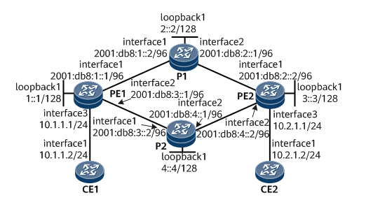
as Figure 1 As shown in:
-
Routers PE1, P1, P2 and PE2 belong to the same autonomous system. They are required to achieve the purpose of IPv6 network interconnection through IS-IS protocol.
-
PE1, P1, P2 and PE2 belong to IS-IS process 1 and are all Level-2 devices.
It is required to establish a two-way SRv6 BE path between PE1 and PE2 to carry L3VPNv4 services. At the same time, in order to make full use of network resources, the L3VPNv4 service carried by SRv6 BE between PE1 and PE2 is required to carry out equivalent load sharing (ECMP).
Figure 1 # configuration of L3VPNv4 over SRv6 BE ECMP networking diagram
Configuration ideas
-
Enable the IPv6 forwarding capability of PE1, P1, P2 and PE2 interfaces, and configure the IPv6 address of each interface.
-
Enable IS-IS on PE1, P1, P2 and PE2, configure the Level level and specify the network entity. At the same time, configure dynamic BFD for IPv6 IS-IS.
-
Configure VPN instances on PE1 and PE2.
-
Establish EBGP peer relationship between PE and CE.
-
Establish MP-IBGP peer relationship between PE S.
-
Configure SRv6 on PE1 and PE2. Configure SRv6 capability of IS-IS.
Operation steps
1. Enable the IPv6 forwarding capability of each interface and configure the IPv6 address. Taking PE1 as an example, the configuration process of other routers is the same and will not be repeated
<HUAWEI> system-view
[~HUAWEI] sysname PE1
[*HUAWEI] commit
[~PE1] interface gigabitethernet 1/0/0
[~PE1-GigabitEthernet1/0/0] ipv6 enable
[*PE1-GigabitEthernet1/0/0] ipv6 address 2001:db8:1::1 96
[*PE1-GigabitEthernet1/0/0] quit
[*PE1] interface gigabitethernet 2/0/0
[*PE1-GigabitEthernet2/0/0] ipv6 enable
[*PE1-GigabitEthernet2/0/0] ipv6 address 2001:db8:3::1 96
[*PE1-GigabitEthernet2/0/0] quit
[*PE1] interface LoopBack 1
[*PE1-LoopBack1] ipv6 enable
[*PE1-LoopBack1] ipv6 address 1::1 128
[*PE1-LoopBack1] quit
[*PE1] commit
2. Configure IS-IS
When configuring IS-IS, the dynamic BFD function is enabled at the same time to improve the convergence speed of IS-IS when the link state changes.
#Configure PE1.
[~PE1] bfd
[*PE1-bfd] quit
[*PE1] isis 1
[*PE1-isis-1] is-level level-2
[*PE1-isis-1] cost-style wide
[*PE1-isis-1] network-entity 10.0000.0000.0001.00
[*PE1-isis-1] ipv6 enable topology ipv6
[*PE1-isis-1] ipv6 bfd all-interfaces enable
[*PE1-isis-1] quit
[*PE1] interface gigabitethernet 1/0/0
[*PE1-GigabitEthernet1/0/0] isis ipv6 enable 1
[*PE1-GigabitEthernet1/0/0] quit
[*PE1] interface gigabitethernet 2/0/0
[*PE1-GigabitEthernet2/0/0] isis ipv6 enable 1
[*PE1-GigabitEthernet2/0/0] quit
[*PE1] interface loopback1
[*PE1-LoopBack1] isis ipv6 enable 1
[*PE1-LoopBack1] commit
[~PE1-LoopBack1] quit
#Configure P1.
[~P1] bfd
[*P1-bfd] quit
[*P1] isis 1
[*P1-isis-1] is-level level-2
[*P1-isis-1] cost-style wide
[*P1-isis-1] network-entity 10.0000.0000.0002.00
[*P1-isis-1] ipv6 enable topology ipv6
[*P1-isis-1] ipv6 bfd all-interfaces enable
[*P1-isis-1] quit
[*P1] interface gigabitethernet 1/0/0
[*P1-GigabitEthernet1/0/0] isis ipv6 enable 1
[*P1-GigabitEthernet1/0/0] quit
[*P1] interface gigabitethernet 2/0/0
[*P1-GigabitEthernet2/0/0] isis ipv6 enable 1
[*P1-GigabitEthernet2/0/0] quit
[*P1] interface loopback1
[*P1-LoopBack1] isis ipv6 enable 1
[*P1-LoopBack1] commit
[~P1-LoopBack1] quit
#Configure P2.
[~P2] bfd
[*P2-bfd] quit
[*P2] isis 1
[*P2-isis-1] is-level level-2
[*P2-isis-1] cost-style wide
[*P2-isis-1] network-entity 10.0000.0000.0004.00
[*P2-isis-1] ipv6 enable topology ipv6
[*P2-isis-1] ipv6 bfd all-interfaces enable
[*P2-isis-1] quit
[*P2] interface gigabitethernet 1/0/0
[*P2-GigabitEthernet1/0/0] isis ipv6 enable 1
[*P2-GigabitEthernet1/0/0] quit
[*P2] interface gigabitethernet 2/0/0
[*P2-GigabitEthernet2/0/0] isis ipv6 enable 1
[*P2-GigabitEthernet2/0/0] quit
[*P2] interface loopback1
[*P2-LoopBack1] isis ipv6 enable 1
[*P2-LoopBack1] commit
[~P2-LoopBack1] quit
#Configure PE2.
[~PE2] bfd
[*PE2-bfd] quit
[*PE2] isis 1
[*PE2-isis-1] is-level level-2
[*PE2-isis-1] cost-style wide
[*PE2-isis-1] network-entity 10.0000.0000.0003.00
[*PE2-isis-1] ipv6 enable topology ipv6
[*PE2-isis-1] ipv6 bfd all-interfaces enable
[*PE2-isis-1] quit
[*PE2] interface gigabitethernet 1/0/0
[*PE2-GigabitEthernet1/0/0] isis ipv6 enable 1
[*PE2-GigabitEthernet1/0/0] quit
[*PE2] interface gigabitethernet 2/0/0
[*PE2-GigabitEthernet2/0/0] isis ipv6 enable 1
[*PE2-GigabitEthernet2/0/0] quit
[*PE2] interface loopback1
[*PE2-LoopBack1] isis ipv6 enable 1
[*PE2-LoopBack1] commit
[~PE2-LoopBack1] quit
After the configuration is completed, you can check whether the IS-IS configuration is successful according to the following instructions.
#Displays IS-IS neighbor information. Take PE1 as an example.
[~PE1] display isis peer

                          Peer information for ISIS(1)

  System Id     Interface          Circuit Id        State HoldTime Type     PRI
--------------------------------------------------------------------------------
0000.0000.0004* GE2/0/0            0000.0000.0004.02  Up   7s       L2       64
0000.0000.0002* GE1/0/0            0000.0000.0002.02  Up   9s       L2       64

Total Peer(s): 2
#Displays IS-IS routing table information. Take PE1 as an example.
[~PE1] display isis route
                         Route information for ISIS(1)
                         -----------------------------

                        ISIS(1) Level-2 Forwarding Table
                        --------------------------------

 IPV6 Dest.     ExitInterface      NextHop                    Cost     Flags
--------------------------------------------------------------------------------
1::/128         Loop1              Direct                     0        D/-/L/-
2::/128         GE1/0/0            FE80::3A92:6CFF:FE31:307   10       A/-/-/-
3::/128         GE1/0/0            FE80::3A92:6CFF:FE31:307   20       A/-/-/-
                GE2/0/0            FE80::3A92:6CFF:FE41:305
4::/128         GE2/0/0            FE80::3A92:6CFF:FE41:305   10       A/-/-/-
2001:DB8:1::/96 GE1/0/0            Direct                     10       D/-/L/-
2001:DB8:2::/96 GE1/0/0            FE80::3A92:6CFF:FE31:307   20       A/-/-/-
2001:DB8:3::/96 GE2/0/0            Direct                     10       D/-/L/-
2001:DB8:4::/96 GE2/0/0            FE80::3A92:6CFF:FE41:305   20       A/-/-/-
     Flags: D-Direct, A-Added to URT, L-Advertised in LSPs, S-IGP Shortcut,
            U-Up/Down Bit Set, LP-Local Prefix-Sid
     Protect Type: L-Link Protect, N-Node Protect
3. Configure a VPN instance that enables IPv4 address family on the PE device and connect CE to PE
#Configure PE1.
[~PE1] ip vpn-instance vpna
[*PE1-vpn-instance-vpna] ipv4-family
[*PE1-vpn-instance-vpna-af-ipv4] route-distinguisher 100:1
[*PE1-vpn-instance-vpna-af-ipv4] vpn-target 111:1 both
[*PE1-vpn-instance-vpna-af-ipv4] quit
[*PE1-vpn-instance-vpna] quit
[*PE1] interface gigabitethernet 3/0/0
[*PE1-GigabitEthernet3/0/0] ip binding vpn-instance vpna
[*PE1-GigabitEthernet3/0/0] ip address 10.1.1.1 24
[*PE1-GigabitEthernet3/0/0] quit
[*PE1] commit
#Configure PE2.
[~PE2] ip vpn-instance vpna
[*PE2-vpn-instance-vpna] ipv4-family
[*PE2-vpn-instance-vpna-af-ipv4] route-distinguisher 200:1
[*PE2-vpn-instance-vpna-af-ipv4] vpn-target 111:1 both
[*PE2-vpn-instance-vpna-af-ipv4] quit
[*PE2-vpn-instance-vpna] quit
[*PE2] interface gigabitethernet 3/0/0
[*PE2-GigabitEthernet3/0/0] ip binding vpn-instance vpna
[*PE2-GigabitEthernet3/0/0] ip address 10.2.1.1 24
[*PE2-GigabitEthernet3/0/0] quit
[*PE2] commit
#Press Figure 1 Configure the interface IP address of each CE. Please refer to the following configuration file for the configuration process.
After configuration, execute the display IP VPN instance verbose command on the PE device to see the configuration of the VPN instance. Each PE can ping its own CE.
4. Establish EBGP peer relationship between PE and CE
#Configure CE1.
[~CE1] interface loopback 1
[*CE1-LoopBack1] ip address 11.11.11.11 32
[*CE1-LoopBack1] quit
[*CE1] bgp 65410
[*CE1-bgp] peer 10.1.1.1 as-number 100
[*CE1-bgp] network 11.11.11.11 32
[*CE1-bgp] quit
[*CE1] commit
#Configure PE1.
[~PE1] bgp 100
[*PE1-bgp] router-id 1.1.1.1
[*PE1-bgp] ipv4-family vpn-instance vpna
[*PE1-bgp-vpna] peer 10.1.1.2 as-number 65410
[*PE1-bgp-vpna] import-route direct
[*PE1-bgp-vpna] commit
[~PE1-bgp-vpna] quit
[~PE1-bgp] quit
#Configure CE2.
[~CE2] interface loopback 1
[*CE2-LoopBack1] ip address 22.22.22.22 32
[*CE2-LoopBack1] quit
[*CE2] bgp 65420
[*CE2-bgp] peer 10.2.1.1 as-number 100
[*CE2-bgp] network 22.22.22.22 32
[*CE2-bgp] quit
[*CE2] commit
#Configure PE2.
[~PE2] bgp 100
[*PE2-bgp] router-id 2.2.2.2
[*PE2-bgp] ipv4-family vpn-instance vpna
[*PE2-bgp-vpna] peer 10.2.1.2 as-number 65420
[*PE2-bgp-vpna] import-route direct
[*PE2-bgp-vpna] commit
[~PE2-bgp-vpna] quit
[~PE2-bgp] quit
After the configuration is completed, execute the display BGP VPN 4 VPN instance peer command on the PE device. You can see that the BGP peer relationship between PE and CE has been Established and reached the Established state.
Take the peer relationship between PE1 and CE1 as an example:
[~PE1] display bgp vpnv4 vpn-instance vpna peer
 BGP local router ID : 1.1.1.1
 Local AS number : 100

 VPN-Instance vpna, Router ID 1.1.1.1:
 Total number of peers : 1            Peers in established state : 1

  Peer            V    AS  MsgRcvd  MsgSent    OutQ  Up/Down    State        PrefRcv
  10.1.1.2        4   65410  11     9          0     00:06:37   Established  1
5. Establish MP-IBGP peer relationship between PE S
#Configure PE1.
[~PE1] bgp 100
[~PE1-bgp] peer 3::3 as-number 100
[*PE1-bgp] peer 3::3 connect-interface loopback 1
[*PE1-bgp] ipv4-family vpnv4
[*PE1-bgp-af-vpnv4] peer 3::3 enable
[*PE1-bgp-af-vpnv4] commit
[~PE1-bgp-af-vpnv4] quit
[~PE1-bgp] quit
#Configure PE2.
[~PE2] bgp 100
[~PE2-bgp] peer 1::1 as-number 100
[*PE2-bgp] peer 1::1 connect-interface loopback 1
[*PE2-bgp] ipv4-family vpnv4
[*PE2-bgp-af-vpnv4] peer 1::1 enable
[*PE2-bgp-af-vpnv4] commit
[~PE2-bgp-af-vpnv4] quit
[~PE2-bgp] quit
After the configuration is completed, execute the display BGP VPN 4 all peer command on the PE device. You can see that the BGP peer relationship between PES has been Established and reached the Established state.
6. Establish SRv6 BE path between PE S
#Configure PE1.
[~PE1] segment-routing ipv6
[*PE1-segment-routing-ipv6] encapsulation source-address 1::1
[*PE1-segment-routing-ipv6] locator as1 ipv6-prefix 10:: 64 static 32
[*PE1-segment-routing-ipv6-locator] quit
[*PE1-segment-routing-ipv6] quit
[*PE1] bgp 100
[*PE1-bgp] ipv4-family vpnv4
[*PE1-bgp-af-vpnv4] peer 3::3 prefix-sid
[*PE1-bgp-af-vpnv4] quit
[*PE1-bgp] ipv4-family vpn-instance vpna
[*PE1-bgp-vpna] segment-routing ipv6 best-effort
[*PE1-bgp-vpna] segment-routing ipv6 locator as1
[*PE1-bgp-vpna] commit
[~PE1-bgp-vpna] quit
[~PE1-bgp] quit
[~PE1] isis 1
[~PE1-isis-1] segment-routing ipv6 locator as1
[*PE1-isis-1] commit
[~PE1-isis-1] quit
#Configure PE2.
[~PE2] segment-routing ipv6
[*PE2-segment-routing-ipv6] encapsulation source-address 3::3
[*PE2-segment-routing-ipv6] locator as1 ipv6-prefix 30:: 64 static 32
[*PE2-segment-routing-ipv6-locator] quit
[*PE2-segment-routing-ipv6] quit
[*PE2] bgp 100
[*PE2-bgp] ipv4-family vpnv4
[*PE2-bgp-af-vpnv4] peer 1::1 prefix-sid
[*PE2-bgp-af-vpnv4] quit
[*PE2-bgp] ipv4-family vpn-instance vpna
[*PE2-bgp-vpna] segment-routing ipv6 best-effort
[*PE2-bgp-vpna] segment-routing ipv6 locator as1
[*PE2-bgp-vpna] commit
[~PE2-bgp-vpna] quit
[~PE2-bgp] quit
[~PE2] isis 1
[~PE2-isis-1] segment-routing ipv6 locator as1
[*PE2-isis-1] commit
[~PE2-isis-1] quit
7. Check the configuration results
Execute command display ip routing-table vpn-instance vpna IP address verbose view VPN routing information. Take the display of PE1 as an example:
[~PE1] display ip routing-table vpn-instance vpna 22.22.22.22 32 verbose
Route Flags: R - relay, D - download to fib, T - to vpn-instance, B - black hole route
------------------------------------------------------------------------------
Routing Table : vpna
Summary Count : 1

Destination: 22.22.22.22/32
     Protocol: IBGP               Process ID: 0
   Preference: 255                      Cost: 0
      NextHop: 30::1:0:20          Neighbour: 3::3
        State: Active Adv Relied         Age: 00h00m23s
          Tag: 0                    Priority: low
        Label: 3                     QoSInfo: 0x0
   IndirectID: 0x10000C7            Instance:
 RelayNextHop: 30::1:0:20          Interface: SRv6 BE
     TunnelID: 0x0                     Flags: RD
It can be seen from the above display information that VPN route 22.22.22.22/32 iterates to SRv6 BE path.
View the details of IPv6 Routing with the destination address of routing next hop 30:: 1:0:20.
[~PE1] display ipv6 routing-table 30::1:0:20 verbose
Route Flags: R - relay, D - download to fib, T - to vpn-instance, B - black hole route
------------------------------------------------------------------------------
Routing Table : _public_
Summary Count : 2

Destination  : 30::                                    PrefixLength : 64
NextHop      : FE80::3A92:6CFF:FE31:307                Preference   : 15
Neighbour    : ::                                      ProcessID    : 1
Label        : NULL                                    Protocol     : ISIS-L2
State        : Active Adv                              Cost         : 20
Entry ID     : 0                                       EntryFlags   : 0x00000000
Reference Cnt: 0                                       Tag          : 0
Priority     : medium                                  Age          : 132sec
IndirectID   : 0x1000085                               Instance     :
RelayNextHop : ::                                      TunnelID     : 0x0
Interface    : GigabitEthernet1/0/0                    Flags        : D

Destination  : 30::                                    PrefixLength : 64
NextHop      : FE80::3A92:6CFF:FE41:305                Preference   : 15
Neighbour    : ::                                      ProcessID    : 1
Label        : NULL                                    Protocol     : ISIS-L2
State        : Active Adv                              Cost         : 20
Entry ID     : 0                                       EntryFlags   : 0x00000000
Reference Cnt: 0                                       Tag          : 0
Priority     : medium                                  Age          : 132sec
IndirectID   : 0x1000087                               Instance     :
RelayNextHop : ::                                      TunnelID     : 0x0
Interface    : GigabitEthernet2/0/0                    Flags        : D
As can be seen from the above display information, route 30:: 1:0:20 has two outgoing interfaces, and ECMP will be formed during forwarding.
CE of the same VPN can Ping each other, for example:
[~CE1] ping -a 11.11.11.11 22.22.22.22
  PING 22.22.22.22: 56  data bytes, press CTRL_C to break
    Reply from 22.22.22.22: bytes=56 Sequence=1 ttl=253 time=7 ms
    Reply from 22.22.22.22: bytes=56 Sequence=2 ttl=253 time=5 ms
    Reply from 22.22.22.22: bytes=56 Sequence=3 ttl=253 time=4 ms
    Reply from 22.22.22.22: bytes=56 Sequence=4 ttl=253 time=5 ms
    Reply from 22.22.22.22: bytes=56 Sequence=5 ttl=253 time=5 ms

  --- 22.22.22.22 ping statistics ---
    5 packet(s) transmitted
    5 packet(s) received
    0.00% packet loss
    round-trip min/avg/max = 4/5/7 ms