1, Design tasks and requirements
- The simple water tower water level controller has four water level detection inputs
- From low to high, they are HL, H2, H3 and H4 respectively
- Motors with 380V AC aerodynamic power of 10KW are ml and M2 respectively;
- The controller controls the operation of the motor according to the water level state
2. Control requirements
- Water level detection, which is not affected by long-term blister working environment;
- When the water level is lower than H1, ML and M2 work at the same time; When the water level is higher than H4, the initial water level is the same as m2
Shutdown; - When the water level rises from H 1 to H 3, turn off ml;
- When the water level drops from H 4 to H2, open M1;
3. Control requirements for standby pump
- When any one of the two working motors fails, it shall be able to detect the fault
- And put the standby motor into operation. After the standby motor is put into operation, there are corresponding instructions for the faulty motor.
2, Results
3, Main references
[1] Peng Jiehua Tuen Zi technical course design guidance [M] Beijing: Higher Education Press, 1997
[2] Kang Huaguang, digital electronic technology, Beijing: Higher Education Press,
abstract
The task of this course design is to realize the simple water level controller, which is on the premise of mastering the relevant knowledge of digital electronic technology
 A combination of theory and practice.
Based on the study and understanding of 555 chip and low voltage relay
 This design adopts NE555 The chip combines relay, contactor and buoyancy switch to
 Realize the detection of water level and automatic control and protection of motor. In order to prove the feasibility of the design
〜This design uses Multisim The software simulates the chip control circuit
〜The simulation results are attached in the paper.
This paper is the instruction of curriculum design
〜It mainly introduces how this design uses digital electronics and other related technologies to realize water level control
〜The implementation mode and principle of each function block are introduced in detail
〜And the components used.
introduction
This design uses digital electronic technology and relay, contactor and other related knowledge to realize the control of water level to motor.
Compared with previous classroom teaching, curriculum design puts forward higher requirements for us,
It needs to be flexibly applied based on the professional knowledge learned or to be learned, and finally form a•A complete product.
In the design of this subject, due to the limitation of design cycle,
As well as the limitations of task requirements, only an original system is designed to meet the problem requirements
 Use in design Multisim The simulation software analyzes the feasibility of the system
 And try to consider the problems that may occur in the actual operation
 Ensure that the designed products can operate normally.
However, due to the limited knowledge and ability, there are many imperfections that need to be improved.
System overview
Water level controller is a common automatic instrument in daily life
 This course requires the use of digital electronic technology and other knowledge to design a water level controller.
According to the design requirements, the system adopts the combination of strong and weak current.
Weak current part
- Step down rectifier circuit
- 555 trigger circuit(NE555)
- relay(KA)
- Buoyancy switch, etc.
The step-down rectifier circuit provides DC voltage for the whole control circuit
 trigger circuit NE555 The water level of the water tower is detected according to its trigger characteristics.
The strong current part is composed of fuse and AC contactor(KM)And motor and other equipment. one
Task analysis and design scheme determination
The theme of this course is to design a simple water level controller.
The water level controller uses power electronics related technology to complete a series of automation work, such as water level detection and control, motor start-up and shutdown, fault motor protection and standby motor input.
From the control requirements of the task, the designed system needs to be at the specified water level(Low to high H1 Startup and shutdown of two motors,H4)The specific relationship between on and off of the motor is as follows:
Relationship between water level and opening and closing of motor
| Trigger water level | Water level rise? | Water level drop? | Water level rise? | Water level drop? |
|---|---|---|---|---|
| H1 | open | open | open | open |
| H2 | open | open | open | shut |
| H3 | shut | shut | open | shut |
| H4 | shut | shut | shut | shut |
It can be seen from the table that the opening and closing of the two motors are at the water level from H2 to IJH3 The process is different,
Therefore, this design uses two chips to control two motors respectively.
Used in many chips NE555 Chip composition RS The trigger is the core of the control part.
Because the control part involves chip and low-power relay coil
- Therefore, less than 24 must be used V Voltage source drive
- The motor requires 10 KW The power must be three-phase asynchronous motor, so it needs three-phase power supply to drive.
Then the weak current part can start from 220 V The step-down transformer is used to obtain electric energy in the municipal power supply
 The control part of strong current can be directly from the three-phase power supply connected to the motor,
- 220 is obtained by connecting the two phases with the high voltage end of the step-down transformer V Voltage.
In addition, the control part must also control the motor driving part
- Then the intermediate relay can be used as a bridge between strong and weak current to realize the control of weak current to strong current part.
- However, for motor failure and switching of standby generator, AC contactor and fuse can be configured in the motor control part to realize this requirement.
- In addition, in the design of water level detection input port, in order to ensure that the detection port will not be affected by long-term blisters.
- Therefore, anti-corrosion materials such as metal stainless steel and low-voltage devices that use the buoyancy principle to control the closing of wires are used as the detection port.
Division and implementation of function blocks
- According to the task analysis above, the function block division and implementation mode of this design are described in detail. Firstly, after the circuit of weak current part is divided according to function, the implementation method of each part is as follows:
(1) Step down rectifier circuit:
Step down transformer from 220 V Obtain electric energy from municipal power.
And use four 1 N4002 A capacitor filter circuit is composed of a transistor and a capacitor to rectify and filter the low-voltage AC.
Provide stable DC power for the control circuit.
(2) Control circuit:
Use two NE555 Each chip is composed of RS Trigger is the core control component.
The signal end is connected with the water level switch circuit, and the output end is connected with the relay coil.
Because the system requires weak current to control strong current, and the function of intermediate relay is to control high current and high voltage equipment with small current and low voltage in the circuit.
Therefore, the low-power intermediate relay is used as the link between the two.
(3) water level detection
Circuit:The buoyancy switch popular in the market is used to place it at the specified water level of the water tower.
The two switches cooperate with each other to realize the input of standby motor and the indication of fault motor.
Similarly, apply for a fuse at the place where each part of the circuit is directly connected with the power supply to protect the equipment.
1.3 overall block diagram and working principle
(1) the principle block diagram of this design is shown in Figure 1-1
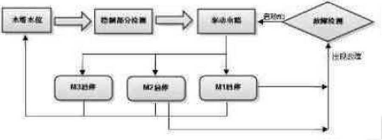
Figure 1-1 Schematic block diagram of simple water level controller
2) Introduction to overall working principle
- Water level monitoring and control principle	:Here only for M1 Brief analysis of motor start and stop control, M2 The control of motor can be obtained in the same way.
- For the convenience of description, the following pins 2 and 6 are high potential, which means that the input voltage is high>Vcc and〉Vcc.
- When the liquid level is lower than the minimum water level Hl When, all buoyancy switches are off,
- here NE555 If pins 2 and 6 of the chip are low potential, the output is high potential, and both ends are connected to NE555 Relay of chip output pin and ground wire(KA1)The coil is energized,
- And drive the normally open contacts installed in the control parts of the two main motors to close, making the AC contactor connected in series with them(KM1)The coil is energized,
- At the same time, it drives the corresponding normally open contact to close, so that Ml The motor is connected to the power grid and the motor can be started. When the water level reaches H2 after(That is, buoyancy switches 1 and 2 are closed),
- NE555 The two pins of the chip are high potential and the six pins are low potential. At this time, the output terminal remains in the state of high potential and the motor remains running.
- When the liquid level is higher than the water level H3 When, NE555 Pins 2 and 6 of the chip are high potential, and the output potential immediately changes to 0 V,Make the voltage at both ends of the relay coil 0 V,	The normally open contact of the motor control part is restored to make the AC contactor connected in series with it(KM1)No current passes through the coil, resulting in the disconnection of the corresponding normally open contact,
- bring Ml The motor is disconnected from the power grid and the motor stops.
- But the liquid level is higher than the maximum water level H4 When, buoyancy switch 4 is closed
- NE555 Reset terminal potential of the chip Vcc Immediately drop to close to 0 V,Reset the chip and the output voltage is 0 V,
- Similarly, the motor stops?
Motor fault detection and input principle of standby motor:
-  The fault of the motor in normal operation is generally three-phase short circuit, overload and phase loss.
- This design uses the circuit breaker with electromagnetic release QF Overload and short circuit protection,
- Use current transformer and current relay in parallel for open phase protection.
- When any current relay is energized, the normally open contact connected in series in the motor control circuit is disconnected;
- The normally closed contact connected in series in the starting circuit of the standby motor is closed(It turns out that the coil is disconnected when it is charged),
- Resulting in the same relay in one branch(KM)Coil power loss,
- As a result, the relay contact connected with the motor and the power grid is disconnected, and the faulty motor stops running
- At the same time, the fault indication and the starting function of the standby motor are realized.