The tutorial is constantly updated: http://www.armbbs.cn/forum.php?mod=viewthread&tid=98429
Chapter 8: emwin6 X with OS mode migration (RGB interface of STM32H7)
This chapter explains emWin6 X is transplanted in bare metal mode. The migration method provided supports the implementation of multi-layer configuration, multi buffer configuration and various color formats of emWin. At the same time, it can adapt to our 4.3-inch, 5-inch and 7-inch resistive and capacitive screens.
Although this chapter takes our development board as an example for transplantation, teaching everyone how to transplant to their own board and precautions in the process of transplantation are the focus of this chapter.
catalogue
8.1 important tips for beginners
8.2 # preparations before transplantation and procedures for transplantation of emWin
8.3 # step 1: download the emWin library and add it to the project template
8.4 # step 2: implementation of SDRAM driver
8.5 step 3: pin configuration and timing configuration involved in LTDC
8.5.1 LTDC timing configuration
8.5.2 how to verify whether the timing configuration of LTDC is correct
8.5.3 add all documents involved to the project
8.6 step 4: realization of touch drive of resistive screen and capacitive screen
8.6.1 add three events of pressing, releasing and moving GUIX
8.6.2} call the touch scan function periodically
8.6.3 how to transplant the touch driver to your own board
8.7 # step 5: emWin underlying interface function and configuration
8.7.3 LCDConf_Lin_Template.c Documents
8.8 step 6: RTOS mode interface file of emWin
8.9 # step 7: MPU Cache configuration of SDRAM
8.10 step 8: add emWin application for testing
8.11 solution to flicker of display screen
8.12 avoid highlighting and tearing of the display screen at the moment of power on
8.1 important tips for beginners
1. Before learning this chapter, make sure you have learned chapters 4, 5 and 6 of this tutorial. These three chapters are the necessary knowledge before transplantation.
2. In order to facilitate the transplantation, it is recommended to directly add our project files to our own project or directly use our project template. It can be transplanted according to the modification instructions in this chapter. This chapter takes uCOS-III transplantation as an example.
3. This chapter takes transplanting to MDK as an example. If transplanting to IAR, the method is the same.
4. Source and precautions of emWin library used in this tutorial:
- The emWin library used in this tutorial is from emWin6.0 in the installation directory of MDK x.
- Because the version of STemWin has been stuck in V5 44 version, so we didn't use it in this chapter. If you use STemWin, you must remember to enable the hardware CRC clock of STM32 before initializing emWin, because ST officials protect their emWin library, otherwise emWin cannot be started.
5. Because the development board needs to adapt to 4.3-inch, 5-inch and 7-inch display screens, and can also be divided into resistance touch and capacitance touch, a little more files are added in the migration process. Although the transplantation is explained with our development board as an example, the focus is still to tell you how to transplant your own board and the matters needing attention in the process of transplantation.
6. For the transplantation of this chapter, we need to control it as a whole. Since the development board has sorted out the files to be transplanted, users can use them only by adding files. Here we focus on how to transplant it to our own board, which is the focus of this chapter.
- Transplantation of display screen
All the underlying interface functions required by emWin have been integrated in lcdconf_ Lin_ Template. In the C file, this file is relatively mature and basically free of bug s. For this file, users only need to learn to use a few macro configurations and provide a display backlight adjustment function LCD_SetBackLight is OK, and there is no need to modify anything else.
In addition, there is a problem of pin and timing configuration involved in LTDC, which needs to be realized by the user. The configuration method has been explained in section 4.6 of this chapter. If this configuration is completed, the display migration of emWin is completed.
- Transplantation of touch
The transplantation of capacitive touch is relatively easy, because the capacitive touch chip can automatically touch calibration, so you only need to configure the touch chip and pass the touch coordinates returned by the touch chip (the capacitive touch chip returns the actual coordinate value) and the touch press state through the function GUI_ PID_ Store the storestate in the FIFO of the pointer input device.
The transplantation of resistance touch is a little troublesome. Because the linearity of resistance touch panel is not very good, there will be inaccurate clicks and flying points if touch calibration and filtering are not done. emWin itself supports two-point touch calibration. In the actual test, it is found that the effect is not very good, and flying points are easy to appear, especially the resistive touch pad with poor linearity. To solve this problem, we have specially made a four point touch calibration, and the actual effect is much better. The touch filtering method is to delay 30ms after detecting the touch, eliminate the jitter, then collect 10 groups of coordinate values for ascending arrangement, remove the largest and smallest groups of coordinates, and average the middle groups as the final value (the capacitance touch chip returns the ADC value, not the actual coordinate value). Then substitute the final value into the linear formula established through touch calibration to obtain the actual coordinate value. At this time, the touch coordinates and touch press state can be through the function GUI_PID_StoreState is stored in the FIFO of the pointer input device.
8.2 # preparations before transplantation and procedures for transplantation of emWin
Before transplantation, pay attention to the following two issues:
- The IDE development environment in this chapter must be mdk5 Version 30 and above, image download address:
http://www.armbbs.cn/forum.php?mod=viewthread&tid=96992 . .
- Prepare a simple uCOS-III project (the same as other RTOS). The simpler it is, the better. We can transplant it on this simple project.
http://www.armbbs.cn/forum.php?mod=viewthread&tid=96918 .
The migration of emWin library is completed through the following 8 steps, and each step is explained in detail in the following subsections:
8.3 # step 1: download the emWin library and add it to the project template
(Note: the simplest way to realize the operation in this section is to copy the emWin folder in the tutorial supporting example to your own project directory).
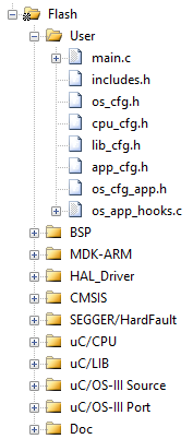
First, prepare a simple bare metal engineering template. The production of engineering template will not be explained. The focus here is to teach you transplantation. The prepared project template is shown in the figure below (you can also make any other project template, without limitation):
http://www.armbbs.cn/forum.php?mod=viewthread&tid=96918
After preparing the project template, you can start the migration. The first thing to do is to put all the required documents into the project template. The following is divided into four steps to explain to you. Of course, there is no restriction that you must use the following method to add the source code to the project, as long as you add the required files to the project template.
Step 1: find the emWin software package according to the method explained in section 2.3.5 of Chapter 2. The following is the content of the emWin software package:
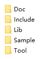
We have simply sorted it out. It is recommended that you directly use the emWin folder of the supporting examples of this chapter's tutorial in the migration stage and copy it into your own project.
Step 2: create emWin folder in the project template
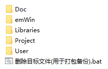
The following subfolders are created in the emWin folder to facilitate our management:
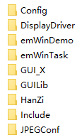
- The Config folder is used to add configuration files and emWin underlying driver interface files.
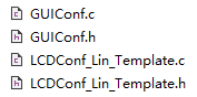
These four files are from the Config folder in the emWin package.
- DisplayDriver is the default driver and is not used.
- emWinTask file is used to add users' own application code files.
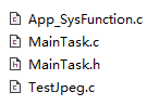
These four files are test codes that need to be implemented by users themselves, and the migration only uses maintask C and maintask h. Here, you can directly copy the two files in this folder:
- GUI_X file is used to add interface files in bare metal or RTOS mode.
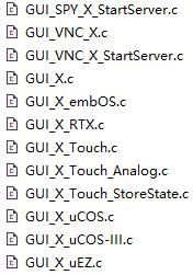
Where GUI_X_uCOS-III.c is for RTOS.
- GUILib file is used to add emWin library files.
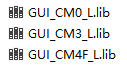
GUI_ CM0_ 50. Lib for M0 kernel chip, GUI_ CM3_ 50. Lib is used for new M3 kernel and GUI_ CM4_ 50. Lib is used for M4 and M7 core chips. All three libraries are in small end format.
- HanZi Chinese font file.
It is used to add emWin Chinese character library, which is not used in the current migration stage.
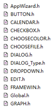
- The Include file is used to add header files.
Most header files of emWin are in this file. Some screenshots:
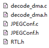
- JPEGConf is used for hard JPEG decoding of STM32H7.
This is a hardware decoding interface file specially designed for H7 (not designed by SEGGER, but designed by ourselves).
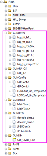
Step 3: add the source code file to the MDK project. The effect after adding is as follows:
After adding, don't forget to add the path of the header file:
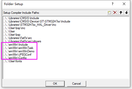
So far, all the emWin files we need have been added.
8.4 # step 2: implementation of SDRAM driver
(Note: the simplest way to realize the operation in this section is to copy the SDRAM driver in the tutorial supporting example to its own project directory for debugging and modification)
It must be ensured that SDRAM is normal when reading and writing data in large quantities. SDRAM test can be conducted under a special engineering test. For the driver implementation of SDRAM, you can see the SDRAM chapter of BSP driver tutorial: http://www.armbbs.cn/forum.php?mod=viewthread&tid=86980
Whether you use MgO, Hynix, Samsung, ISSI or Huabang, the implementation method is basically the same. The board supporting the tutorial uses MgO 32-bit bandwidth SDRAM. If you want to maximize the performance of STM32H7 driving SDRAM, it is strongly recommended to use 32-bit bandwidth SDRAM or two 16 bit SDRAM to form 32-bit bandwidth SDRAM. What role does SDRAM play? There are two functions:
- Video memory for display screen
The LTDC external RGB interface screen of STM32H7 has no video memory, so SDRAM is required for video memory. If the user selects the color format of STM32H7 LTDC as 32-bit color ARGB8888, the required display memory size (unit byte) is: display width * display height * (32 / 8), where 32 / 8 is a pixel representing this color format, which needs 4 bytes. As another example, if RGB565 with 16 bit color format is configured, the required display memory size is: display width * display height * (16 / 8), where 16 / 8 is a pixel representing this color format, which needs 2 bytes. Other color formats, and so on.
- Used as emWin dynamic memory
emWin is extremely dynamic memory consuming, so users can use all the memory of SDRAM except for video memory as emWin dynamic memory.
============================================================
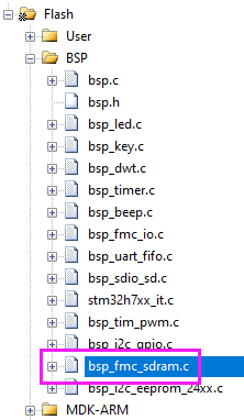
If there is no problem with the SDRAM driver test, you can add it to the project. The SDRAM driver file used by the development board is bsp_fmc_sdram.c.
After being added to the project, the use of SDRAM shall be allocated. The tutorial supporting development board uses 32MB SDRAM with 32-bit bandwidth. Layer 1 occupies 4MB, layer 2 occupies 4MB, and finally 24MB is used for emWin dynamic memory. Some beginners may ask, is 4MB allocated to each layer a little too much? In fact, there are not many, because we need to make different color formats universal, and meet the requirements of three buffers for video memory. If 4MB is allocated here, the tutorial examples are very convenient to use. You can configure the actual size for use in the actual project. The specific configuration is as follows. See BSP for details_ fmc_ sdram. H documents:
#define EXT_SDRAM_ADDR      ((uint32_t)0xC0000000)
#define EXT_SDRAM_SIZE        (32 * 1024 * 1024)

/* LCD Video memory, page 1, allocate 4M bytes */
#define SDRAM_LCD_BUF1         EXT_SDRAM_ADDR

/* LCD Video memory, page 2, allocate 4M bytes */
#define SDRAM_LCD_BUF2        (EXT_SDRAM_ADDR + SDRAM_LCD_SIZE)

#define SDRAM_ LCD_ Size (4 * 1024 * 1024) / * 4M per floor*/
#define SDRAM_ LCD_ Layer 2 / * 2 layers*/

/* The remaining 24M bytes are provided to the application */
#define SDRAM_APP_BUF        (EXT_SDRAM_ADDR + SDRAM_LCD_SIZE * SDRAM_LCD_LAYER)
#define SDRAM_APP_SIZE        (EXT_SDRAM_SIZE - SDRAM_LCD_SIZE * SDRAM_LCD_LAYER)
So far, the driver configuration of SDRAM has also been explained.
8.5 step 3: pin configuration and timing configuration involved in LTDC
8.5.1 LTDC timing configuration
(hint: the simplest way to implement the operation in this section is to copy the example of the driver file LCDConf_Lin_Template.c, which is compiled from the tutorial examples, to the project directory, then debug the function LCD_LL_Init in the modified file, and finally open the display backlight.
Users only need to configure the pins and timing involved in LTDC. The rest of the LTDC configurations are already in the file LCDConf_Lin_Template.c all sealed. The pin configuration is reserved for user configuration because the hardware design is different. For example, RGB888 interface or RGB565 interface may be used, so the user only needs to initialize the required pin. The timing configuration is also reserved because the driving timing is different for the bare screens of different manufacturers.
Since the development board is equipped with 4.3-inch, 5-inch and 7-inch screen displays, it is necessary to adapt these sizes of displays. The timing configuration of each screen is different. The specific implementation is in LCDConf_Lin_Template.c file, that is, function LCD_LL_Init. You only need to provide this LCD when transplanting your own display screen_ LL_ Init function is enough. Pin configuration needs to be implemented in this function.
The pin configuration is relatively easy. You can configure which pins are used in the hardware. The key is the timing configuration of LTDC. To solve this problem, the 4.4 summary in Chapter 4 of this tutorial has a detailed description (must see). We won't repeat it here. The specific code is as follows:
/*
*********************************************************************************************************
*    Function name: LCD_LL_Init
*    Function Description: configure LTDC
*    Formal parameter: None
*    Return value: None
*   Notes:
*       LCD_TFT Synchronous timing configuration (a screenshot compiled from the official, concise and comprehensive):
*       ----------------------------------------------------------------------------
*
*                                                 Total Width
*                             <--------------------------------------------------->
*                       Hsync width HBP             Active Width                HFP
*                             <---><--><--------------------------------------><-->
*                         ____    ____|_______________________________________|____
*                             |___|   |                                       |    |
*                                     |                                       |    |
*                         __|         |                                       |    |
*            /|\    /|\  |            |                                       |    |
*             | VSYNC|   |            |                                       |    |
*             |Width\|/  |__          |                                       |    |
*             |     /|\     |         |                                       |    |
*             |  VBP |      |         |                                       |    |
*             |     \|/_____|_________|_______________________________________|    |
*             |     /|\     |         | / / / / / / / / / / / / / / / / / / / |    |
*             |      |      |         |/ / / / / / / / / / / / / / / / / / / /|    |
*    Total    |      |      |         |/ / / / / / / / / / / / / / / / / / / /|    |
*    Heigh    |      |      |         |/ / / / / / / / / / / / / / / / / / / /|    |
*             |Active|      |         |/ / / / / / / / / / / / / / / / / / / /|    |
*             |Heigh |      |         |/ / / / / / Active Display Area / / / /|    |
*             |      |      |         |/ / / / / / / / / / / / / / / / / / / /|    |
*             |      |      |         |/ / / / / / / / / / / / / / / / / / / /|    |
*             |      |      |         |/ / / / / / / / / / / / / / / / / / / /|    |
*             |      |      |         |/ / / / / / / / / / / / / / / / / / / /|    |
*             |      |      |         |/ / / / / / / / / / / / / / / / / / / /|    |
*             |     \|/_____|_________|_______________________________________|    |
*             |     /|\     |                                                      |
*             |  VFP |      |                                                      |
*            \|/    \|/_____|______________________________________________________|
*
*
*     Each LCD device has its own synchronization timing value:
*     Horizontal Synchronization (Hsync)
*     Horizontal Back Porch (HBP)
*     Active Width
*     Horizontal Front Porch (HFP)
*
*     Vertical Synchronization (Vsync)
*     Vertical Back Porch (VBP)
*     Active Heigh
*     Vertical Front Porch (VFP)
*
*     LCD_TFT Horizontal and vertical start and end positions of the window:
*     ----------------------------------------------------------------
*
*     HorizontalStart = (Offset_X + Hsync + HBP);
*     HorizontalStop  = (Offset_X + Hsync + HBP + Window_Width - 1);
*     VarticalStart   = (Offset_Y + Vsync + VBP);
*     VerticalStop    = (Offset_Y + Vsync + VBP + Window_Heigh - 1);
*
*********************************************************************************************************
*/
static void LCD_LL_Init(void)
{
    /* Configure GPIO related to LCD */
    {
        /* GPIOs Configuration */
        /*
        +------------------------+-----------------------+----------------------------+
        +                       LCD pins assignment                                   +
        +------------------------+-----------------------+----------------------------+
        |  LCDH7_TFT R0 <-> PI.15  |  LCDH7_TFT G0 <-> PJ.07 |  LCDH7_TFT B0 <-> PJ.12      |
        |  LCDH7_TFT R1 <-> PJ.00  |  LCDH7_TFT G1 <-> PJ.08 |  LCDH7_TFT B1 <-> PJ.13      |
        |  LCDH7_TFT R2 <-> PJ.01  |  LCDH7_TFT G2 <-> PJ.09 |  LCDH7_TFT B2 <-> PJ.14      |
        |  LCDH7_TFT R3 <-> PJ.02  |  LCDH7_TFT G3 <-> PJ.10 |  LCDH7_TFT B3 <-> PJ.15      |
        |  LCDH7_TFT R4 <-> PJ.03  |  LCDH7_TFT G4 <-> PJ.11 |  LCDH7_TFT B4 <-> PK.03      |
        |  LCDH7_TFT R5 <-> PJ.04  |  LCDH7_TFT G5 <-> PK.00 |  LCDH7_TFT B5 <-> PK.04      |
        |  LCDH7_TFT R6 <-> PJ.05  |  LCDH7_TFT G6 <-> PK.01 |  LCDH7_TFT B6 <-> PK.05      |
        |  LCDH7_TFT R7 <-> PJ.06  |  LCDH7_TFT G7 <-> PK.02 |  LCDH7_TFT B7 <-> PK.06      |
        -------------------------------------------------------------------------------
        |  LCDH7_TFT HSYNC <-> PI.12  | LCDTFT VSYNC <->  PI.13 |
        |  LCDH7_TFT CLK   <-> PI.14  | LCDH7_TFT DE   <->  PK.07 |
        -----------------------------------------------------
        */
        GPIO_InitTypeDef GPIO_Init_Structure;

        /*##-1- Enable peripherals and GPIO Clocks #################################*/
        /* Enable LTDC and DMA2D clocks */
        __HAL_RCC_LTDC_CLK_ENABLE();
        __HAL_RCC_DMA2D_CLK_ENABLE();

        /* Enable GPIO clock */
        __HAL_RCC_GPIOI_CLK_ENABLE();
        __HAL_RCC_GPIOJ_CLK_ENABLE();
        __HAL_RCC_GPIOK_CLK_ENABLE();

        /* GPIOI to configure */
        GPIO_Init_Structure.Pin       = GPIO_PIN_12 | GPIO_PIN_13 | GPIO_PIN_14 | GPIO_PIN_15;
        GPIO_Init_Structure.Mode      = GPIO_MODE_AF_PP;
        GPIO_Init_Structure.Pull      = GPIO_NOPULL;
        GPIO_Init_Structure.Speed     = GPIO_SPEED_FREQ_HIGH;
        GPIO_Init_Structure.Alternate = GPIO_AF14_LTDC;
        HAL_GPIO_Init(GPIOI, &GPIO_Init_Structure);

        /* GPIOJ to configure */
        GPIO_Init_Structure.Pin       = GPIO_PIN_0 | GPIO_PIN_1 | GPIO_PIN_2 | GPIO_PIN_3 | \
                                      GPIO_PIN_4 | GPIO_PIN_5 | GPIO_PIN_6 | GPIO_PIN_7 | \
                                      GPIO_PIN_8 | GPIO_PIN_9 | GPIO_PIN_10 | GPIO_PIN_11 | \
                                      GPIO_PIN_12 | GPIO_PIN_13 | GPIO_PIN_14 | GPIO_PIN_15;
        GPIO_Init_Structure.Mode      = GPIO_MODE_AF_PP;
        GPIO_Init_Structure.Pull      = GPIO_NOPULL;
        GPIO_Init_Structure.Speed     = GPIO_SPEED_FREQ_HIGH;
        GPIO_Init_Structure.Alternate = GPIO_AF14_LTDC;
        HAL_GPIO_Init(GPIOJ, &GPIO_Init_Structure);

        /* GPIOK to configure */
        GPIO_Init_Structure.Pin       = GPIO_PIN_0 | GPIO_PIN_1 | GPIO_PIN_2 | GPIO_PIN_3 | \
                                      GPIO_PIN_4 | GPIO_PIN_5 | GPIO_PIN_6 | GPIO_PIN_7;
        GPIO_Init_Structure.Mode      = GPIO_MODE_AF_PP;
        GPIO_Init_Structure.Pull      = GPIO_NOPULL;
        GPIO_Init_Structure.Speed     = GPIO_SPEED_FREQ_HIGH;
        GPIO_Init_Structure.Alternate = GPIO_AF14_LTDC;
        HAL_GPIO_Init(GPIOK, &GPIO_Init_Structure);
    }

    /*##-2- LTDC Initialize#############################################################*/
    {
        uint16_t Width, Height, HSYNC_W, HBP, HFP, VSYNC_W, VBP, VFP;
        RCC_PeriphCLKInitTypeDef  PeriphClkInitStruct = {0};

        /* Support 6 kinds of panels */
        switch (g_LcdType)
        {
            case LCD_35_480X320:    /* 3.5 Inch 480 * 320 */
                Width = 480;
                Height = 272;
                HSYNC_W = 10;
                HBP = 20;
                HFP = 20;
                VSYNC_W = 20;
                VBP = 20;
                VFP = 20;
                break;

            case LCD_43_480X272:        /* 4.3 Inch 480 * 272 */
                Width = 480;
                Height = 272;

                HSYNC_W = 40;
                HBP = 2;
                HFP = 2;
                VSYNC_W = 9;
                VBP = 2;
                VFP = 2;

                /* LCD Clock configuration */
                /* PLL3_VCO Input = HSE_VALUE/PLL3M = 25MHz/5 = 5MHz */
                /* PLL3_VCO Output = PLL3_VCO Input * PLL3N = 5MHz * 48 = 240MHz */
                /* PLLLCDCLK = PLL3_VCO Output/PLL3R = 240 / 10 = 24MHz */
                /* LTDC clock frequency = PLLLCDCLK = 24MHz */
                /*
                    Refresh rate = 24MHz / ((width + hsync_w + HBP + HFP) * (height + vsync_w + VBP + VFP))
                              = 24000000/((480 + 40  + 2  + 2)*(272 + 9 +  2  + 2))
                           = 24000000/(524*285)
                           = 160Hz

                    At present, this configuration is convenient for users to use the 48MHz clock output by PLL3Q for USB.
                */
                PeriphClkInitStruct.PeriphClockSelection = RCC_PERIPHCLK_LTDC;
                PeriphClkInitStruct.PLL3.PLL3M = 5;
                PeriphClkInitStruct.PLL3.PLL3N = 24;
                PeriphClkInitStruct.PLL3.PLL3P = 2;
                PeriphClkInitStruct.PLL3.PLL3Q = 5;
                PeriphClkInitStruct.PLL3.PLL3R = 10;
                HAL_RCCEx_PeriphCLKConfig(&PeriphClkInitStruct);
                break;

            case LCD_50_480X272:        /* 5.0 Inch 480 * 272 */
                Width = 480;
                Height = 272;

                HSYNC_W = 40;
                HBP = 2;
                HFP = 2;
                VSYNC_W = 9;
                VBP = 2;
                VFP = 2;
                break;

            case LCD_50_800X480:        /* 5.0 Inch 800 * 480 */
            case LCD_70_800X480:        /* 7.0 Inch 800 * 480 */
                Width = 800;
                Height = 480;

                HSYNC_W = 96;    /* =10 When, the display is misplaced, part of the screen is OK at 20, and all are OK at 80 */
                HBP = 10;
                HFP = 10;
                VSYNC_W = 2;
                VBP = 10;
                VFP = 10;

            ·
                PeriphClkInitStruct.PeriphClockSelection = RCC_PERIPHCLK_LTDC;
                PeriphClkInitStruct.PLL3.PLL3M = 5;
                PeriphClkInitStruct.PLL3.PLL3N = 48;
                PeriphClkInitStruct.PLL3.PLL3P = 2;
                PeriphClkInitStruct.PLL3.PLL3Q = 5;
                PeriphClkInitStruct.PLL3.PLL3R = 10;
                HAL_RCCEx_PeriphCLKConfig(&PeriphClkInitStruct);
                break;

            case LCD_70_1024X600:        /* 7.0 Inch 1024 * 600 */
                /* Measured pixel clock = 53.7M */
                Width = 1024;
                Height = 600;

                HSYNC_W = 2;    /* =10 When, the display is misplaced, part of the screen is OK at 20, and all are OK at 80 */
                HBP = 157;
                HFP = 160;
                VSYNC_W = 2;
                VBP = 20;
                VFP = 12;

                PeriphClkInitStruct.PeriphClockSelection = RCC_PERIPHCLK_LTDC;
                PeriphClkInitStruct.PLL3.PLL3M = 5;
                PeriphClkInitStruct.PLL3.PLL3N = 48;
                PeriphClkInitStruct.PLL3.PLL3P = 2;
                PeriphClkInitStruct.PLL3.PLL3Q = 5;
                PeriphClkInitStruct.PLL3.PLL3R = 10;
                HAL_RCCEx_PeriphCLKConfig(&PeriphClkInitStruct);
                break;

            default:
                Width = 800;
                Height = 480;

                HSYNC_W = 80;    /* =10 When, the display is misplaced, part of the screen is OK at 20, and all are OK at 80 */
                HBP = 10;
                HFP = 10;
                VSYNC_W = 10;
                VBP = 10;
                VFP = 10;

                /* LCD Clock configuration */
                /* PLL3_VCO Input = HSE_VALUE/PLL3M = 25MHz/5 = 5MHz */
                /* PLL3_VCO Output = PLL3_VCO Input * PLL3N = 5MHz * 48 = 240MHz */
                /* PLLLCDCLK = PLL3_VCO Output/PLL3R = 240 / 10 = 24MHz */
                /* LTDC clock frequency = PLLLCDCLK = 24MHz */
                /*
                    Refresh rate = 24MHz / ((width + hsync_w + HBP + HFP) * (height + vsync_w + VBP + VFP))
                              = 24000000/((800 + 96  + 10  + 10)*(480 + 2 +  10  + 10))
                           = 24000000/(916*502)
                           = 52Hz

                    It can be increased as needed. There is no problem with the 100Hz refresh rate. Set periphclkinitstruct PLL3. Pll3n = 100
                    At this time, the LTDC clock is 50MHz
                    Refresh rate = 50MHz / ((width + hsync_w + HBP + HFP) * (height + vsync_w + VBP + VFP))
                           = 5000000/(916*502)
                           = 108.7Hz

                    At present, this configuration is convenient for users to use the 48MHz clock output by PLL3Q for USB.
                */
                PeriphClkInitStruct.PeriphClockSelection = RCC_PERIPHCLK_LTDC;
                PeriphClkInitStruct.PLL3.PLL3M = 5;
                PeriphClkInitStruct.PLL3.PLL3N = 48;
                PeriphClkInitStruct.PLL3.PLL3P = 2;
                PeriphClkInitStruct.PLL3.PLL3Q = 5;
                PeriphClkInitStruct.PLL3.PLL3R = 10;
                HAL_RCCEx_PeriphCLKConfig(&PeriphClkInitStruct);
                break;
        }

        g_LcdHeight = Height;
        g_LcdWidth = Width;

        /* Configure signal polarity */
        hltdc.Init.HSPolarity = LTDC_HSPOLARITY_AL;    /* HSYNC Low level active */
        hltdc.Init.VSPolarity = LTDC_VSPOLARITY_AL;     /* VSYNC Low level active */
        hltdc.Init.DEPolarity = LTDC_DEPOLARITY_AL;     /* DE Low level active */
        hltdc.Init.PCPolarity = LTDC_PCPOLARITY_IPC;

        /* Timing configuration */
        hltdc.Init.HorizontalSync = (HSYNC_W - 1);
        hltdc.Init.VerticalSync = (VSYNC_W - 1);
        hltdc.Init.AccumulatedHBP = (HSYNC_W + HBP - 1);
        hltdc.Init.AccumulatedVBP = (VSYNC_W + VBP - 1);
        hltdc.Init.AccumulatedActiveH = (Height + VSYNC_W + VBP - 1);
        hltdc.Init.AccumulatedActiveW = (Width + HSYNC_W + HBP - 1);
        hltdc.Init.TotalHeigh = (Height + VSYNC_W + VBP + VFP - 1);
        hltdc.Init.TotalWidth = (Width + HSYNC_W + HBP + HFP - 1);

        /* Configure background layer color */
        hltdc.Init.Backcolor.Blue = 0;
        hltdc.Init.Backcolor.Green = 0;
        hltdc.Init.Backcolor.Red = 0;

        hltdc.Instance = LTDC;

        /* Configure LTDC  */
        if (HAL_LTDC_Init(&hltdc) != HAL_OK)
        {
            /* Initialization error */
            Error_Handler(__FILE__, __LINE__);
        }
    }

    /* Enable interrupt */
    HAL_LTDC_ProgramLineEvent(&hltdc, 0);

    /* Enable Dither */
    //HAL_LTDC_EnableDither(&hltdc);

    /* Enable LTDC interrupts and configure their priority */
    HAL_NVIC_SetPriority(LTDC_IRQn, 0x2, 0);
    HAL_NVIC_EnableIRQ(LTDC_IRQn);
}
8.5.2 how to verify whether the timing configuration of LTDC is correct
The most important question is how to check whether your configuration is successful after you have configured the timing? The user only needs to be in the function LCD_ LL_ The following code in init is followed by two functions:
/* Configure LTDC  */
if (HAL_LTDC_Init(&hltdc_F) != HAL_OK)
{
    /* Initialization error */
    Error_Handler(__FILE__, __LINE__);
}

/* Here are the added */
LCD_SetBackLight(BRIGHT_DEFAULT);
while(1);
After adding these two lines of code, set the background layer to an appropriate color. It is recommended to set it to red for easy observation:
/* Configure background layer color */
hltdc_F.Init.Backcolor.Blue = 0;
hltdc_F.Init.Backcolor.Green = 0;
hltdc_F.Init.Backcolor.Red = 255;
If the background layer can display red normally, it indicates that there is no problem with the pin and timing configuration. If unsuccessful, check from the following aspects:
- First of all, it should be clear that whether the current configuration is successful has nothing to do with SDRAM, because SDRAM is not used for the background layer, and SDRAM is required for layer 1 and layer 2 as video memory.
- Check from the hardware to ensure that the STM32H7 chip welding is OK, and the TFT interface must be firm to prevent poor contact. Especially when using FPC soft cable, the shorter the soft cable is, the better in the test stage. Sometimes there may be a problem with the display screen. It's best to prepare two display screens for testing.
- Check from the software configuration to see whether all pins involved in LTDC are configured and whether the pin clock is enabled. Sometimes the failure to display may also be caused by large interference caused by non-standard board hardware design. At this time, the speed level of GPIO involved in LTDC can be reduced.
If it is displayed, but the displayed position is incorrect, you can readjust the timing parameters.
8.5.3 add all documents involved to the project
In fact, if you implement it yourself, you only need to modify the function LCD_LL_Init, you can implement this function yourself without any other configuration. Since our development board needs to adapt to different displays, many files are associated. All files about TFT, touch, touch calibration parameter saving and font should be added:
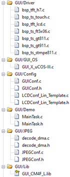
Here is a brief introduction to these newly added files:
- Files in GUI/Driver group
bsp_ tft_ h7. C --- LTDC driver file of stm32h7.
bsp_ tft_ lcd. C --- summary files of TFT driver and related API functions, such as RA8875 display screen, ili9488 display screen and TFT controller driver display screen of F429/H7 can have a separate file, and then summarize the functions with the same functions of these displays into a function. This file plays this role. emWin only uses the global variable g in this file_ LcdHeight,g_LcdWidth and backlight function LCD_SetBackLight, all other functions are not used.
bsp_ts_touch.c --- touch chip adaptive drive, select different drives according to the touch IC used by the user. In addition, touch scanning, touch calibration and touch filtering of resistance screen are also realized in this file.
bsp_ts_gt811.c --- drive of capacitive touch chip GT811 and touch scanning.
bsp_ts_gt911.c --- drive of capacitive touch chip GT911 and touch scanning.
bsp_ts _ft5x06.c --- drive of capacitive touch chip FT5X06 and touch scanning.
bsp_ts_stmpe811.c --- drive of resistance touch chip STMPE811.
- GUI/GUI_ Files in OS group
GUI_ 10. C --- emWin bare metal interface file, mainly the time benchmark and delay implementation of emWin.
- Files in GUI/GUIConfig group
GUIConf.c and H --- setting of EMWIN dynamic memory.
LCDConf_Lin_Template.c and H --- LCD interface file of EMWIN.
- Files in GUI/Demo group
MainTask.c and h--- emWin application design document.
- Files in GUI/JPEG grouping
These files are all used for the hardware JPEG implementation of STM32H7.
- Files in GUI/Lib group
emWin's library file.
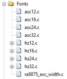
- Files in Fonts group
emWin can't use all these files, just because they are BSP files_ tft_ lcd. C file is associated.
asc12. C -- 12 dot matrix ASCII character font
asc16.c---16 dot matrix ASCII character font
asc24. C -- 24 dot matrix ASCII character font
asc32.c---23 dot matrix ASCII character font
hz12.c --- 12 dot matrix song style small font library
hz16.c --- 16 dot matrix song style small font library
hz24.c --- 24 dot matrix song style small font library
hz32.c --- 32 dot matrix song style small font library
ra8875_ asc_ width. C -- width table of ra8875 ASCII font
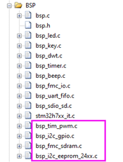
- Files in bsp group
The three files in this group are used indirectly by emWin.
bsp_tim_pwm.c --- driven by timer, PWM is used for backlight of display screen.
bsp_i2c_gpio.c --- I2C interface driver, EEPROM, GT811, GT911, STMPE811 and FT5X06 are all used because their interfaces are I2C mode.
bsp_eeprom_24xx.c --- EEPROM drive, which is used to store the touch calibration parameters of resistance screen.
bsp_fmc_sdram.c --- SDRAM driver file.
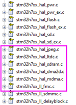
- HAL_ Files in driver group
emWin needs to indirectly use the circled files.
8.6 step 4: realization of touch drive of resistive screen and capacitive screen
The implementation of this section is based on Chapter 5 of this tutorial. The current driver supports the display screens of resistive touch chip STMPE811 and capacitive touch chip FT5X06, GT911 and GT811.
The implementation is relatively simple, because the touch of GUIX is divided into three events: Press, release and move. It happens that the drivers of these touch chips are also divided into these three events, so you only need to modify the function TOUCH_PutKey, all screen touch can be perfectly integrated.
8.6.1 add three events of pressing, releasing and moving GUIX
File BSP_ ts_ touch. Function touch in C_ Putkey is modified as follows:
/*
*********************************************************************************************************
*    Function name: TOUCH_PutKey
*    Function Description: press the coordinate value of one touch point into the touch FIFO buffer. The resistance touch screen parameter is ADC value, and the capacitance touch screen parameter is coordinate value
*    Formal parameters:_ usX, _usY coordinate value
*    Return value: None
*********************************************************************************************************
*/
GUI_PID_STATE State;
void TOUCH_PutKey(uint8_t _ucEvent, uint16_t _usX, uint16_t _usY)
{
#if 1

    uint16_t xx, yy;


    if (g_tTP.Enable == 1)    /* Resistance screen. Parameters are ADC values */
    {
        xx = TOUCH_TransX(_usX, _usY);
        yy = TOUCH_TransY(_usX, _usY);
    }
    else    /* GT811,FTX06,GT911 Capacitor touch takes this part */
    {
        /* Without conversion, it is the coordinate value directly */
        xx = _usX;
        yy = _usY;
    }

    /* Press, move and release events */
    switch (_ucEvent)
    {
        case TOUCH_DOWN:
            State.x = xx;
            State.y = yy;
            State.Pressed = 1;
            GUI_PID_StoreState(&State);
           break;

        case TOUCH_MOVE:
            State.x = xx;
            State.y = yy;
            State.Pressed = 1;
            GUI_PID_StoreState(&State);
           break;

        case TOUCH_RELEASE:
            State.Pressed = 0;
            GUI_PID_StoreState(&State);
            break;

        default:
            break;
    }

#else
    Omit unwritten
#endif
}
Through function GUI_PID_StoreState stores the touch axis in emWin.
8.6.2} call the touch scan function periodically
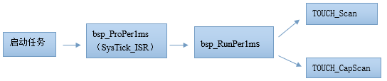
The scanning function of resistive touch and capacitive touch is TOUCH_Scan and TOUCH_CapScan, in order to realize the same calling method when using ThreadX and bare metal, calls the function BSP periodically in the startup task_ Proper1ms (SysTick_ISR), and systick_ BSP is called in ISR_ Runper1ms, then BSP_ The scanning function is called in runper1ms, which is the following calling relationship:
The code is as follows:
/*
*********************************************************************************************************
*    Function name: AppTaskStart
*    Function Description: This is a start task. After the multi task system is started, the tick counter must be initialized. This task mainly realizes key detection.
*    Formal parameter: p_arg is the formal parameter passed when the task is created
*    Return value: None
    Priority: 2
*********************************************************************************************************
*/
static  void  AppTaskStart (void *p_arg)
{
    OS_ERR      err;

   (void)p_arg;

    HAL_ResumeTick();

    CPU_Init(); /* This function should be called first because the us and ms delays used in peripheral drivers are based on this function */
     bsp_Init();
    BSP_OS_TickEnable();

#if OS_CFG_STAT_TASK_EN > 0u
     OSStatTaskCPUUsageInit(&err);
#endif

#ifdef CPU_CFG_INT_DIS_MEAS_EN
    CPU_IntDisMeasMaxCurReset();
#endif

    /* Create task */
    AppTaskCreate();

    /* Create inter task communication mechanism */
    AppObjCreate();

    while (1)
    {
        /* Programs that need periodic processing correspond to systick called by bare metal projects_ ISR */
        bsp_ProPer1ms();
        OSTimeDly(1, OS_OPT_TIME_PERIODIC, &err);
    }
}
8.6.3 how to transplant the touch driver to your own board
Through the previous explanation, the simplest way to transplant the touch driver to your own board is to transplant all the touch related files of the development board, and then modify them on the basis of these files. The following two cases are described:
- The transplantation of capacitive screen touch is relatively simple. If the user's touch IC is the same as the development board, it can be used directly. If it is different, the driver of the touch IC needs to be realized first, and then one can be realized according to the touch scanning function of GT911, GT811 or FT5X06 provided by the development board.
- The transplantation of resistance screen is a little troublesome. If the touch IC used by the user is the same as the development board, it can be used directly. If it is different, the driver of touch IC needs to be realized first, and then emulate bsp_ts_stmpe811.c file provides touch press status function, ADC value reading function of X-axis and Y-axis and function of clearing touch interrupt flag. Finally, replace BSP with the re implemented functions_ ts_ touch. C file can be the original function. In addition, it should be noted that after this method is realized, although the touch calibration can still be used, the touch calibration parameters of the development board are saved in EEPROM, and users can choose the storage medium according to their actual situation. In addition, the storage and reading of touch parameters are in bsp_ts_touch.c function touch at the end of the file_ Saveparam and TOUCH_LoadParam implementation.
If you don't want to use the development board to implement a scheme, it's no problem to re implement it yourself. Pay attention to the way associated with emWin.
8.7 # step 5: emWin underlying interface function and configuration
The implementation of the underlying interface function and configuration of emWin is guiconf C and its header file and LCDConf_Lin_Template.c and its header file. Let's introduce these four documents respectively.
8.7.1 GUIConf.c Documents
GUIConf.c file mainly realizes the configuration of system dynamic memory. We have made the following modifications based on the official code and added a macro definition to facilitate users to choose whether to use internal SRAM or external SDRAM as the dynamic memory of emWin:
#include "GUI.h"
#include "bsp.h"


/*********************************************************************
*
*       Defines
*
**********************************************************************
*/
//
// Define the available number of bytes available for the GUI
//
#define EX_SRAM   1/*1 used extern sram, 0 used internal sram */   //--------------(1)

#if EX_SRAM
#define GUI_NUMBYTES  (1024*1024*24)
#else
#define GUI_NUMBYTES  (100*1024)
#endif

/* Define the average block size */
#define GUI_BLOCKSIZE 0x80          //--------------(2)


/*********************************************************************
*
*       Public code
*
**********************************************************************
*/
/*********************************************************************
*
*       GUI_X_Config
*
* Purpose:
*   Called during the initialization process in order to set up the
*   available memory for the GUI.
*/
void GUI_X_Config(void)
{
#if EX_SRAM                                    //--------------(3)
    static U32 *aMemory;
    aMemory = (U32 *)SDRAM_APP_BUF;

    /*  Assign memory to emWin */
    GUI_ALLOC_AssignMemory(aMemory, GUI_NUMBYTES);
    GUI_ALLOC_SetAvBlockSize(GUI_BLOCKSIZE);
#else                                         //--------------(4)
//    /* 32 bit aligned memory area */
//    static U32 aMemory[GUI_NUMBYTES / 4];
    static U32 *aMemory;
    aMemory = (U32 *)0x24000000;
    /*  Assign memory to emWin */
    GUI_ALLOC_AssignMemory(aMemory, GUI_NUMBYTES);
    GUI_ALLOC_SetAvBlockSize(GUI_BLOCKSIZE);
#endif
}
1. Configure whether to use internal SRAM or external SDRAM as the dynamic memory of emWin through macro definition. When configuring:
#define EX_SRAM # 1 means using external SDRAM as emWin dynamic memory, with a size of 24MB. The specific size is defined by the macro #define GUI_NUMBYTES (1024 * 1024 * 24).
#define EX_SRAM # 0 means using internal SRAM as emWin dynamic memory, with a size of 100KB. The specific size is defined by the macro #define GUI_NUMBYTES (100 * 1024).
By default, all emWin examples supporting this tutorial use external SDRAM as emWin dynamic memory.
2. Configure to use external SDRAM as emWin dynamic memory, where SDRAM_APP_BUF is the first address of emWin dynamic memory. Through function GUI_ALLOC_AssignMemory allocates dynamic memory for emWin. Note that the unit of the second parameter is bytes.
Through function GUI_ALLOC_SetAvBlockSize configures the memory block size. The size range recommended in the official manual is 32 bytes to 1024 bytes. Generally, 0x80, i.e. 128 bytes, is used.
3. Configure to use internal SRAM as emWin dynamic memory. The local static variable array defined therein is emWin dynamic memory.
Here we set up a 100KB space using AXI SRAM.
8.7.2 GUIConf.h file
This file is mainly the default system configuration. The code is as follows:
#ifndef GUICONF_H
#define GUICONF_H

/*********************************************************************
*
*       Multi layer/display support
*/

#define GUI_NUM_LAYERS            2    /* Maximum number of available layers */
#define OS_SUPPORT
/*********************************************************************
*
*       Multi tasking support
*/
#ifdef OS_SUPPORT
 #define GUI_OS                    (1)  /* Compile with multitasking support */
#else
 #define GUI_OS                    (0)
#endif

/*********************************************************************
*
*       Configuration of touch support
*/
#ifndef   GUI_SUPPORT_TOUCH
  #define GUI_SUPPORT_TOUCH       (1)  /* Support touchscreen */
#endif

/*********************************************************************
*
*       Default font
*/
#define GUI_DEFAULT_FONT          &GUI_Font6x8

/*********************************************************************
*
*         Configuration of available packages
*/
#define GUI_SUPPORT_MOUSE             (1)    /* Support a mouse */
#define GUI_WINSUPPORT                (1)    /* Use window manager */
#define GUI_SUPPORT_MEMDEV            (1)    /* Memory device package available */
#define GUI_SUPPORT_DEVICES           (1)    /* Enable use of device pointers */
#define BUTTON_REACT_ON_LEVEL         (1)    /* Enable button reaction on level */
#define GUI_MEMDEV_SUPPORT_CUSTOMDRAW (1)    /* Enable use of memdev custom draw */
#define GUI_USE_ARGB                  (0)    /* Enable use of ARGB color mode */


#endif  /* Avoid multiple inclusion */
Since emWin is a library file, these macro definition settings have no effect on the library, and API configuration can only be called at runtime. This GUI_USE_ARGB also doesn't work (0 means using ABGR format and 1 means using ARGB format), but common color values are defined by this macro, which is defined in GUI H documents. This macro definition works on the following color values, so you should pay attention to:
/*********************************************************************
*
*       Standard colors
*/
#define GUI_INVALID_COLOR ((((U32)GUI_TRANS_BYTE) << 24) | 0x00ABCDEFul)  /* Invalid color (transparency + determined color) */

#if (GUI_USE_ARGB)
  #define GUI_MAKE_COLOR(ABGR)  (((((U32)ABGR) & 0xFF000000ul) ^ 0xFF000000ul) | ((((U32)ABGR) & 0x00FF0000ul) >> 16) | (((U32)ABGR) & 0x0000FF00ul) | ((((U32)ABGR) & 0x000000FFul) << 16))
  #define GUI_MAKE_TRANS(Alpha) (255 - (Alpha))
#else
  #define GUI_MAKE_COLOR(ABGR)  (ABGR)
  #define GUI_MAKE_TRANS(Alpha) (Alpha)
#endif

#if (GUI_USE_ARGB)
  #define GUI_TRANS_BYTE 0x00
#else
  #define GUI_TRANS_BYTE 0xFF
#endif

#define GUI_BLUE          GUI_MAKE_COLOR(0x00FF0000)
#define GUI_GREEN         GUI_MAKE_COLOR(0x0000FF00)
#define GUI_RED           GUI_MAKE_COLOR(0x000000FF)
#define GUI_CYAN          GUI_MAKE_COLOR(0x00FFFF00)
#define GUI_MAGENTA       GUI_MAKE_COLOR(0x00FF00FF)
#define GUI_YELLOW        GUI_MAKE_COLOR(0x0000FFFF)
#define GUI_LIGHTBLUE     GUI_MAKE_COLOR(0x00FF8080)
#define GUI_LIGHTGREEN    GUI_MAKE_COLOR(0x0080FF80)
#define GUI_LIGHTRED      GUI_MAKE_COLOR(0x008080FF)
#define GUI_LIGHTCYAN     GUI_MAKE_COLOR(0x00FFFF80)
#define GUI_LIGHTMAGENTA  GUI_MAKE_COLOR(0x00FF80FF)
#define GUI_LIGHTYELLOW   GUI_MAKE_COLOR(0x0080FFFF)
#define GUI_DARKBLUE      GUI_MAKE_COLOR(0x00800000)
#define GUI_DARKGREEN     GUI_MAKE_COLOR(0x00008000)
#define GUI_DARKRED       GUI_MAKE_COLOR(0x00000080)
#define GUI_DARKCYAN      GUI_MAKE_COLOR(0x00808000)
#define GUI_DARKMAGENTA   GUI_MAKE_COLOR(0x00800080)
#define GUI_DARKYELLOW    GUI_MAKE_COLOR(0x00008080)
#define GUI_WHITE         GUI_MAKE_COLOR(0x00FFFFFF)
#define GUI_LIGHTGRAY     GUI_MAKE_COLOR(0x00D3D3D3)
#define GUI_GRAY          GUI_MAKE_COLOR(0x00808080)
#define GUI_DARKGRAY      GUI_MAKE_COLOR(0x00404040)
#define GUI_BLACK         GUI_MAKE_COLOR(0x00000000)
#define GUI_BROWN         GUI_MAKE_COLOR(0x002A2AA5)
#define GUI_ORANGE        GUI_MAKE_COLOR(0x0000A5FF)
#define GUI_TRANSPARENT   GUI_MAKE_COLOR(0xFF000000)

#define GUI_GRAY_3F       GUI_MAKE_COLOR(0x003F3F3F)
#define GUI_GRAY_50       GUI_MAKE_COLOR(0x00505050)
#define GUI_GRAY_55       GUI_MAKE_COLOR(0x00555555)
#define GUI_GRAY_60       GUI_MAKE_COLOR(0x00606060)
#define GUI_GRAY_7C       GUI_MAKE_COLOR(0x007C7C7C)
#define GUI_GRAY_9A       GUI_MAKE_COLOR(0x009A9A9A)
#define GUI_GRAY_AA       GUI_MAKE_COLOR(0x00AAAAAA)
#define GUI_GRAY_C0       GUI_MAKE_COLOR(0x00C0C0C0)
#define GUI_GRAY_C8       GUI_MAKE_COLOR(0x00C8C8C8)
#define GUI_GRAY_D0       GUI_MAKE_COLOR(0x00D0D0D0)
#define GUI_GRAY_E7       GUI_MAKE_COLOR(0x00E7E7E7)
#define GUI_BLUE_98       GUI_MAKE_COLOR(0x00980000)
In addition, LCDConf_Lin_Template.c also uses GUI_USE_ARGB macro definition, we should pay attention to the use. In other words, the provided driver file supports both emWin Library in ARGB format and emWin Library in ABGR format. The emWin library provided by MDK only supports ABGR format, while ST provides two format libraries of ARGB and ABGR, but the version of emWin is lower.
8.7.3 LCDConf_Lin_Template.c Documents
It is no exaggeration to say that this file is the most important file in the process of emWin migration. It is mainly configured in this file to realize the display size, display driver, color conversion and underlying optimization of emWin. At present, the driver file has been relatively mature and perfect. In order to improve the driver, we have spent a lot of energy. The multi buffer and multi layer supported by emWin and the common color formats supported by STM32H7 can be configured.
If users want to use this file to configure their own display screen, they can use it directly. The only thing to do is to set the macro definition and modify the function LCD in this file according to their own display screen and project requirements_ LL_ Timing parameters in init and LCD backlight setting function_ Setbacklight (this function should be implemented by yourself. The example provided in the tutorial is implemented in bsp_tft_lcd.c file), and nothing else needs to be modified.
The option macro definitions and comments for users have been very detailed. By default, the emWin examples supporting this tutorial use three buffers, RGB565 format, and only single layer:
/*
**********************************************************************************************************
                                    User configurable options
**********************************************************************************************************
*/
/* 0 These functions are not available for the time being */
#define DrawBitmapA4Enalbe    0
#define ClearCacheHookEnalbe  0
#define DrawAlpha             0
#define UsedDrawBitmap8bpp    0

/*
  1. The physical resolution and driver of the display screen have been adaptive, supporting 4.3-inch, 5-inch and 7-inch screens
     Fill in the maximum resolution in the adaptive display here.
*/
#define XSIZE_PHYS       800
#define YSIZE_PHYS       480

/* 2. Rotation direction. This option is not used yet. You can rotate directly when the project is running */
#define ROTATION_0       0
#define ROTATION_CW      1
#define ROTATION_180     2
#define ROTATION_CCW     3

/*
   3. STM32H7 Supported color modes.
      (1) If you want to use 24 bit color or 32-bit color, select CMS_ARGB8888, if 16 bit color is used, please select CMS_RGB565, other color formats are no longer supported.
      (2) If the user selects ARGB8888 or RGB888 mode and the LCD flashes, check whether it is the problem of this post first:
          http://www.armbbs.cn/forum.php?mod=viewthread&tid=16892 ((for F429 and H7 Series)
          If this is not the problem, you can reduce the LTDC output clock. In the function LCD of this document_ Configltdc
*/
#define CMS_ARGB8888 1
#define CMS_RGB888   2
#define CMS_RGB565   3
#define CMS_ARGB1555 4
#define CMS_ARGB4444 5
#define CMS_L8       6
#define CMS_AL44     7
#define CMS_AL88     8

/* 4. Multi buffer / virtual screen, multi buffer and virtual screen cannot be used at the same time, and emWin does not support it */
#define NUM_ Buffers 3 / * defines the number of multiple buffers. Only 1, 2 and 3 can be set, that is, three buffers are supported at most*/
#define NUM_ Vscreens 1 / * define the number of virtual screens*/

/*
   5. Redefine the number of layers. For STM32H7, you can select one layer or two layers. Three layers are not supported
      (1). Set up GUI_ NUM_ When layers = 1, that is, when only layer 1 is used, the default touch value is sent to layer 1.
      (2). Set up GUI_ NUM_ When layers = 2, that is, both layer 1 and layer 2 have been enabled. At this time, layer 2 is the top layer,
           Users need to set the following two places according to their own usage.
           a. In BSP_ touch. Function touch in C file_ Set the parameter state in inithard Layer = 1, 1 means
              Send touch value to layer 2.
           b. Call GUI_ After the Init function, the function GUI_ is called. Selectlayer (1), set layer 2 for the current operation.
*/
#undef  GUI_NUM_LAYERS
#define GUI_NUM_LAYERS 1

/*
   6. Set the video memory address corresponding to layer 1 and layer 2
      (1) EXT_SDRAM_ADDR Is the first address of SDRAM.
      (2) LCD_LAYER0_FRAME_BUFFER Is the video memory address of layer 1.
      (3) LCD_LAYER1_FRAME_BUFFER Is the video memory address of layer 2.
      (4) The display memory size of each layer is exquisite. Here is a simple description.
          If the color mode selected by the user = 32-bit color ARGB8888, the size of the video memory:
          XSIZE_PHYS * YSIZE_PHYS * 4 * NUM_VSCREENS * NUM_BUFFERS

          Color mode = 24 bit color RGB888, size of display memory:
          XSIZE_PHYS * YSIZE_PHYS * 3 * NUM_VSCREENS * NUM_BUFFERS

          Color mode = 16 bit color RGB566, arg1555, argb4444, AL88, then the size of the video memory is:
          XSIZE_PHYS * YSIZE_PHYS * 2 * NUM_VSCREENS * NUM_BUFFERS

          Color mode = 8-bit color L8, AL44, then the size of the video memory is:
          XSIZE_PHYS * YSIZE_PHYS * 1 * NUM_VSCREENS * NUM_BUFFERS

      Here, for convenience, the first 8MB of 24MB SDRAM matched with the development board is allocated to LCD display memory, and the last 24MB is used for emWin dynamic memory.
      For 24 bit color, 16 bit color and 8-bit color, users can enable three buffers and double layers. But 32-bit color also enables triple buffering and double buffering
      The layer will exceed 8MB, so users can adjust the allocation of video memory and emWin dynamic memory according to their own situation.
        For example, for an 800 * 480 resolution display screen, if 32-bit color and three buffers are enabled, the final size of a layer is
      800 * 480 * 4 * 3  = 4.394MB If it is a double layer, it has exceeded the allocation range of 8MB.

      (5)For convenience, the macro of layer 2 defines the LCD_ LAYER1_ FRAME_ Parameter 4 in buffer is set according to 32-bit color, if the user's layer 1
         8-digit color is used, and the number 1 is filled in here. If it is 16 digit color, fill in 2 here. If it is 24 digit color, fill in 3 here.
*/
#define LCD_LAYER0_FRAME_BUFFER  EXT_SDRAM_ADDR
#define LCD_LAYER1_FRAME_BUFFER  (LCD_LAYER0_FRAME_BUFFER + XSIZE_PHYS * YSIZE_PHYS * 4 * NUM_VSCREENS * NUM_BUFFERS)


/* 7. Configure the color mode and resolution size of layer 1 */
#define COLOR_MODE_0  CMS_RGB565
#define ORIENTATION_0 ROTATION_0
#define XSIZE_0       XSIZE_PHYS
#define YSIZE_0       YSIZE_PHYS

/* 8. Configure the color mode and resolution size of layer 2 */
#define COLOR_MODE_1  CMS_RGB565
#define ORIENTATION_1 ROTATION_0
#define XSIZE_1       XSIZE_PHYS
#define YSIZE_1       YSIZE_PHYS

/* 9. When no layer is activated, the background color setting is not used temporarily */
#define BK_COLOR      GUI_DARKBLUE


/* 10. In the case of single layer, the color mode of emWin of layer 1 can be automatically selected according to the color mode selected by the user */
#if   (COLOR_MODE_0 == CMS_ARGB8888)
  #define COLOR_CONVERSION_0 GUICC_M8888I
#elif (COLOR_MODE_0 == CMS_RGB888)
  #define COLOR_CONVERSION_0 GUICC_M888
#elif (COLOR_MODE_0 == CMS_RGB565)
  #define COLOR_CONVERSION_0 GUICC_M565
#elif (COLOR_MODE_0 == CMS_ARGB1555)
  #define COLOR_CONVERSION_0 GUICC_M1555I
#elif (COLOR_MODE_0 == CMS_ARGB4444)
  #define COLOR_CONVERSION_0 GUICC_M4444I
#elif (COLOR_MODE_0 == CMS_L8)
  #define COLOR_CONVERSION_0 GUICC_8666
#elif (COLOR_MODE_0 == CMS_AL44)
  #define COLOR_CONVERSION_0 GUICC_1616I
#elif (COLOR_MODE_0 == CMS_AL88)
  #define COLOR_CONVERSION_0 GUICC_88666I
#else
  #error Illegal color mode 0!
#endif

/* 11. In the case of single layer, the emWin driver of layer 1 can be automatically selected according to the color mode selected by the user */
#if   (COLOR_MODE_0 == CMS_ARGB8888)
  #if   (ORIENTATION_0 == ROTATION_0)
    #define DISPLAY_DRIVER_0   GUIDRV_LIN_32
  #elif (ORIENTATION_0 == ROTATION_CW)
    #define DISPLAY_DRIVER_0   GUIDRV_LIN_OSX_32
  #elif (ORIENTATION_0 == ROTATION_180)
    #define DISPLAY_DRIVER_0   GUIDRV_LIN_OXY_32
  #elif (ORIENTATION_0 == ROTATION_CCW)
    #define DISPLAY_DRIVER_0   GUIDRV_LIN_OSY_32
  #endif
#elif (COLOR_MODE_0 == CMS_RGB888)
  #if   (ORIENTATION_0 == ROTATION_0)
    #define DISPLAY_DRIVER_0   GUIDRV_LIN_24
  #elif (ORIENTATION_0 == ROTATION_CW)
    #define DISPLAY_DRIVER_0   GUIDRV_LIN_OSX_24
  #elif (ORIENTATION_0 == ROTATION_180)
    #define DISPLAY_DRIVER_0   GUIDRV_LIN_OXY_24
  #elif (ORIENTATION_0 == ROTATION_CCW)
    #define DISPLAY_DRIVER_0   GUIDRV_LIN_OSY_24
  #endif
#elif (COLOR_MODE_0 == CMS_RGB565)   \
   || (COLOR_MODE_0 == CMS_ARGB1555) \
   || (COLOR_MODE_0 == CMS_ARGB4444) \
   || (COLOR_MODE_0 == CMS_AL88)
  #if   (ORIENTATION_0 == ROTATION_0)
    #define DISPLAY_DRIVER_0   GUIDRV_LIN_16
  #elif (ORIENTATION_0 == ROTATION_CW)
    #define DISPLAY_DRIVER_0   GUIDRV_LIN_OSX_16
  #elif (ORIENTATION_0 == ROTATION_180)
    #define DISPLAY_DRIVER_0   GUIDRV_LIN_OXY_16
  #elif (ORIENTATION_0 == ROTATION_CCW)
    #define DISPLAY_DRIVER_0   GUIDRV_LIN_OSY_16
  #endif
#elif (COLOR_MODE_0 == CMS_L8)   \
   || (COLOR_MODE_0 == CMS_AL44)
  #if   (ORIENTATION_0 == ROTATION_0)
    #define DISPLAY_DRIVER_0   GUIDRV_LIN_8
  #elif (ORIENTATION_0 == ROTATION_CW)
    #define DISPLAY_DRIVER_0   GUIDRV_LIN_OSX_8
  #elif (ORIENTATION_0 == ROTATION_180)
    #define DISPLAY_DRIVER_0   GUIDRV_LIN_OXY_8
  #elif (ORIENTATION_0 == ROTATION_CCW)
    #define DISPLAY_DRIVER_0   GUIDRV_LIN_OSY_8
  #endif
#endif


/* 12. In the case of two layers, the color mode of emWin of layer 2 can be automatically selected according to the color mode selected by the user */
#if (GUI_NUM_LAYERS > 1)
#if   (COLOR_MODE_1 == CMS_ARGB8888)
  #define COLOR_CONVERSION_1 GUICC_M8888I
#elif (COLOR_MODE_1 == CMS_RGB888)
  #define COLOR_CONVERSION_1 GUICC_M888
#elif (COLOR_MODE_1 == CMS_RGB565)
  #define COLOR_CONVERSION_1 GUICC_M565
#elif (COLOR_MODE_1 == CMS_ARGB1555)
  #define COLOR_CONVERSION_1 GUICC_M1555I
#elif (COLOR_MODE_1 == CMS_ARGB4444)
  #define COLOR_CONVERSION_1 GUICC_M4444I
#elif (COLOR_MODE_1 == CMS_L8)
  #define COLOR_CONVERSION_1 GUICC_8666
#elif (COLOR_MODE_1 == CMS_AL44)
  #define COLOR_CONVERSION_1 GUICC_1616I
#elif (COLOR_MODE_1 == CMS_AL88)
  #define COLOR_CONVERSION_1 GUICC_88666I
#else
  #error Illegal color mode 0!
#endif

/* 13. In the case of double layers, the emWin driver of layer 2 can be automatically selected according to the color mode selected by the user */
#if   (COLOR_MODE_1 == CMS_ARGB8888)
  #if   (ORIENTATION_1 == ROTATION_0)
    #define DISPLAY_DRIVER_1   GUIDRV_LIN_32
  #elif (ORIENTATION_1 == ROTATION_CW)
    #define DISPLAY_DRIVER_1   GUIDRV_LIN_OSX_32
  #elif (ORIENTATION_1 == ROTATION_180)
    #define DISPLAY_DRIVER_1   GUIDRV_LIN_OXY_32
  #elif (ORIENTATION_1 == ROTATION_CCW)
    #define DISPLAY_DRIVER_1   GUIDRV_LIN_OSY_32
  #endif
#elif (COLOR_MODE_1 == CMS_RGB888)
  #if   (ORIENTATION_1 == ROTATION_0)
    #define DISPLAY_DRIVER_1   GUIDRV_LIN_24
  #elif (ORIENTATION_1 == ROTATION_CW)
    #define DISPLAY_DRIVER_1   GUIDRV_LIN_OSX_24
  #elif (ORIENTATION_1 == ROTATION_180)
    #define DISPLAY_DRIVER_1   GUIDRV_LIN_OXY_24
  #elif (ORIENTATION_1 == ROTATION_CCW)
    #define DISPLAY_DRIVER_1   GUIDRV_LIN_OSY_24
  #endif
#elif (COLOR_MODE_1 == CMS_RGB565)   \
   || (COLOR_MODE_1 == CMS_ARGB1555) \
   || (COLOR_MODE_1 == CMS_ARGB4444) \
   || (COLOR_MODE_1 == CMS_AL88)
  #if   (ORIENTATION_1 == ROTATION_0)
    #define DISPLAY_DRIVER_1   GUIDRV_LIN_16
  #elif (ORIENTATION_1 == ROTATION_CW)
    #define DISPLAY_DRIVER_1   GUIDRV_LIN_OSX_16
  #elif (ORIENTATION_1 == ROTATION_180)
    #define DISPLAY_DRIVER_1   GUIDRV_LIN_OXY_16
  #elif (ORIENTATION_1 == ROTATION_CCW)
    #define DISPLAY_DRIVER_1   GUIDRV_LIN_OSY_16
  #endif
#elif (COLOR_MODE_1 == CMS_L8)   \
   || (COLOR_MODE_1 == CMS_AL44)
  #if   (ORIENTATION_1 == ROTATION_0)
    #define DISPLAY_DRIVER_1   GUIDRV_LIN_8
  #elif (ORIENTATION_1 == ROTATION_CW)
    #define DISPLAY_DRIVER_1   GUIDRV_LIN_OSX_8
  #elif (ORIENTATION_1 == ROTATION_180)
    #define DISPLAY_DRIVER_1   GUIDRV_LIN_OXY_8
  #elif (ORIENTATION_1 == ROTATION_CCW)
    #define DISPLAY_DRIVER_1   GUIDRV_LIN_OSY_8
  #endif
#endif

#else

#undef XSIZE_0
#undef YSIZE_0
#define XSIZE_0 XSIZE_PHYS
#define YSIZE_0 YSIZE_PHYS

#endif

/*14. Configuration option detection to prevent configuration errors or some options are not configured */
#if NUM_BUFFERS > 3
  #error More than 3 buffers make no sense and are not supported in this configuration file!
#endif
#ifndef   XSIZE_PHYS
  #error Physical X size of display is not defined!
#endif
#ifndef   YSIZE_PHYS
  #error Physical Y size of display is not defined!
#endif
#ifndef   NUM_BUFFERS
  #define NUM_BUFFERS 1
#else
  #if (NUM_BUFFERS <= 0)
    #error At least one buffer needs to be defined!
  #endif
#endif
#ifndef   NUM_VSCREENS
  #define NUM_VSCREENS 1
#else
  #if (NUM_VSCREENS <= 0)
    #error At least one screeen needs to be defined!
  #endif
#endif
#if (NUM_VSCREENS > 1) && (NUM_BUFFERS > 1)
  #error Virtual screens together with multiple buffers are not allowed!
#endif
==============
This document will not be expanded here to explain to you, because it involves a lot of content and a little heavy workload. However, in order to satisfy the students who love research, explain how to learn this document, so that you can get twice the result with half the effort, or you don't know where to start:
- The most important function in this file is LCD_X_Config and function LCD_X_DisplayDriver, except for the LTDC line interrupt function, all other functions are called directly or indirectly by these two functions. Interested students can associate all the layers of the functions called by these two functions on paper, and then break them one by one, so as to have a more comprehensive understanding.
- After clarifying the relationship of various functions in this file, it is necessary to understand the function LCD_X_Config and function LCD_ X_ How displaydriver is called by emWin. The answer to this question has been given in the configuration section of the emWin official manual, which is the following screenshot:
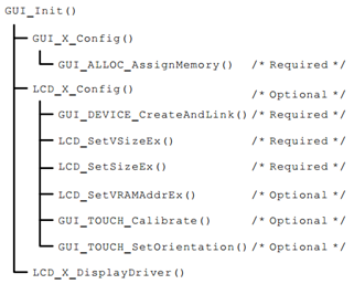
As can be seen from the screenshot above, the function LCD_X_Config and function LCD_X_DisplayDriver initializes the GUI in the function called by the user_ Init is called in turn.
(in particular, most API s are optimized and accelerated by DMA2D, which is described in detail in Chapter 6 of this tutorial)
8.8 step 6: RTOS mode interface file of emWin
The RTOS mode interface file of emWin is the GUI added in step 1_ X_ uCOS-III.c file, the interface file of RTOS mode, is relatively comprehensive in the installation directory of MDK. Small operating systems such as embOS, RTX, FreeRTOS and uEZ provide interfaces, including GUI_X_uCOS.c file is based on uCOS II, and there is no interface file of UCOS III, so you need to implement it yourself. Our GUI_ X_ The uCOS-III.c interface file is modeled on the GUI_X_uCOS.c implementation.
GUI_ X_ The code implementation of ucos-iii.c is as follows:
#include <os.h>
#include "GUI_Private.H"

/*
*********************************************************************************************************
*                                         GLOBAL VARIABLES
*********************************************************************************************************
*/

static  OS_SEM  DispSem;
static  OS_SEM  EventSem;

static  OS_SEM  KeySem;
static  int     KeyPressed;
static  char    KeyIsInited;


/*
*********************************************************************************************************
*                                        TIMING FUNCTIONS
*
* Notes: Some timing dependent routines of uC/GUI require a GetTime and delay funtion.
*        Default time unit (tick), normally is 1 ms.
*********************************************************************************************************
*/

int  GUI_X_GetTime (void)  //--------------(1)
{
    OS_TICK  time_cur;
    OS_ERR   os_err;

    time_cur = OSTimeGet(&os_err);
   (void)&os_err;

    return ((int)time_cur);
}

void  GUI_X_Delay (int period)  //--------------(2)
{
    OS_ERR      err;
    OSTimeDly(period, OS_OPT_TIME_DLY, &err);
}


/*
*********************************************************************************************************
*                                          GUI_X_ExecIdle()
*********************************************************************************************************
*/
void GUI_X_ExecIdle (void)  //--------------(3)
{
    GUI_X_Delay(1);
}


/*
*********************************************************************************************************
*                                    MULTITASKING INTERFACE FUNCTIONS
*
* Note(1): 1) The following routines are required only if uC/GUI is used in a true multi task environment,
*             which means you have more than one thread using the uC/GUI API.  In this case the #define
*             GUI_OS 1   needs to be in GUIConf.h
*********************************************************************************************************
*/

void  GUI_X_InitOS (void)  //--------------(4)
{
    OS_ERR     err;

    /* cnt = 1 for resource sharing*/
    OSSemCreate((OS_SEM    *)&DispSem,
                (CPU_CHAR  *)"DispSem",
                (OS_SEM_CTR )1,
                (OS_ERR    *)&err);
    /* cnt = 0 for event triggering*/
    OSSemCreate((OS_SEM    *)&EventSem,
                (CPU_CHAR  *)"EventSem",
                (OS_SEM_CTR )0,
                (OS_ERR    *)&err);
}

void  GUI_X_Lock (void)   //--------------(5)
{
    OS_ERR     err;

    OSSemPend((OS_SEM *)&DispSem,
              (OS_TICK )0,
              (OS_OPT  )OS_OPT_PEND_BLOCKING,
              (CPU_TS  )0,
              (OS_ERR *)&err);
}

void  GUI_X_Unlock (void)  //--------------(6)
{
    OS_ERR     err;

    OSSemPost((OS_SEM *)&DispSem,
              (OS_OPT  )OS_OPT_POST_1,
              (OS_ERR *)&err);
}


U32  GUI_X_GetTaskId (void)   //--------------(7)
{
    CPU_INT16U  id;

    /* Since there are tasks with the same priority, I don't know whether it is OK here. There is no task ID in uCOS-III */
    id = (CPU_INT16U)OSTCBCurPtr->Prio;

    return ((U32)id);
}

/*
*********************************************************************************************************
*                                        GUI_X_WaitEvent()
*                                        GUI_X_SignalEvent()
*********************************************************************************************************
*/


void GUI_X_WaitEvent (void)  //--------------(8)
{
    OS_ERR     err;

    OSSemPend((OS_SEM *)&EventSem,
    (OS_TICK )0,
    (OS_OPT  )OS_OPT_PEND_BLOCKING,
    (CPU_TS  )0,
    (OS_ERR *)&err);
}


void GUI_X_SignalEvent (void)  //--------------(9)
{
    OS_ERR     err;

    OSSemPost((OS_SEM *)&EventSem,
          (OS_OPT  )OS_OPT_POST_1,
          (OS_ERR *)&err);
}

/*
*********************************************************************************************************
*                                      KEYBOARD INTERFACE FUNCTIONS
*
* Purpose: The keyboard routines are required only by some widgets.
*          If widgets are not used, they may be eliminated.
*
* Note(s): If uC/OS-II is used, characters typed into the log window will be placed    in the keyboard buffer.
*          This is a neat feature which allows you to operate your target system without having to use or
*          even to have a keyboard connected to it. (useful for demos !)
*********************************************************************************************************
*/

/*
*********************************************************************************************************
*                                           CheckInit()
*
* Description : Initialize the GUI keyboard if it is not already done.
*
* Argument(s) : none.
*
* Return(s)   : none.
*
* Caller(s)   : GUI_X_WaitKey().
*               GUI_X_GetKey().
*
* Note(s)     : none.
*********************************************************************************************************
*/
void  CheckInit (void)  //--------------(10)
{
    if (KeyIsInited == DEF_FALSE) {
        KeyIsInited = DEF_TRUE;
        GUI_X_Init();
    }
}

/*
*********************************************************************************************************
*                                           GUI_X_Init()
*
* Description : (1) Perform keyboard initialization :
*
*                   (a) Implement keyboard initialization signal by creating a counting semaphore.
*
*                       (1) Initialize keyboard initialization signal with no signal by setting the
*                           semaphore count to 0 to block the semaphore.
*
* Argument(s) : none.
*
* Return(s)   : none.
*
* Caller(s)   : CheckInit().
*
* Note(s)     : none.
*********************************************************************************************************
*/
void GUI_X_Init (void)  //--------------(11)
{
    OS_ERR err;

    OSSemCreate((OS_SEM    *)&KeySem,
                (CPU_CHAR  *)"KeySem",
                (OS_SEM_CTR )0,
                (OS_ERR    *)&err);
}

/*
*********************************************************************************************************
*                                           GUI_X_GetKey()
*
* Description : Get the pressed key.
*
* Argument(s) : none.
*
* Return(s)   : Pressed key.
*
* Caller(s)   : various.
*
* Note(s)     : none.
*********************************************************************************************************
*/
int  GUI_X_GetKey (void)  //--------------(12)
{
    int r;

    r          = KeyPressed;
    CheckInit();
    KeyPressed = 0;
    return (r);
}

/*
*********************************************************************************************************
*                                           GUI_X_WaitKey()
*
* Description : Wait for a key to be pressed and return it.
*
* Argument(s) : none.
*
* Return(s)   : Pressed key.
*
* Caller(s)   : various.
*
* Note(s)     : none.
*********************************************************************************************************
*/
int  GUI_X_WaitKey (void)  //--------------(13)
{
    int    r;
    OS_ERR err;


    CheckInit();
    if (KeyPressed == 0) {
        OSSemPend((OS_SEM *)&EventSem,
        (OS_TICK )0,
        (OS_OPT  )OS_OPT_PEND_BLOCKING,
        (CPU_TS  )0,
        (OS_ERR *)&err);
    }
    r          = KeyPressed;
    KeyPressed = 0;
    return (r);
}

/*
*********************************************************************************************************
*                                          GUI_X_StoreKey()
*
* Description : Store the pressed key.
*
* Argument(s) : Pressed key.
*
* Return(s)   : none.
*
* Caller(s)   : various.
*
* Note(s)     : none.
*********************************************************************************************************
*/
void  GUI_X_StoreKey (int k)   //--------------(14)
{
    OS_ERR     err;

    KeyPressed = k;
    OSSemPost((OS_SEM *)&KeySem,
          (OS_OPT  )OS_OPT_POST_1,
          (OS_ERR *)&err);
}

void GUI_X_Log     (const char *s) { GUI_USE_PARA(s); }  //--------------(15)
void GUI_X_Warn    (const char *s) { GUI_USE_PARA(s); }
void GUI_X_ErrorOut(const char *s) { GUI_USE_PARA(s); }- Function GUI_X_GetTime is used to obtain the system time benchmark. It is realized by calling the system clock beat counting function of uCOS-III.
- Function GUI_X_Delay is used to realize delay by calling the delay function OSTimeDly of uCOS-III.
- Called when emWin's window manager is idle.
- Interface function GUI for emWin multitasking_ X_ Initos, this function creates two semaphores, one for resource sharing and the other for event triggering or signal synchronization.
- Resource lock function GUI_X_Lock.
- Resource unlocking function GUI_X_Unlock.
- Function GUI_X_GetTaskId is used to obtain the task ID. since there is no concept of task ID in uCOS-III, this function uses the task priority as the task ID. this method is also possible, because Micrium does it officially. See this post for details: http://www.armbbs.cn/forum.php?mod=viewthread&tid=18009 .
- Function GUI_X_WaitEvent is used to wait for an event.
- Function GUI_X_SignalEvent is used to release events.
- The following are keyboard interface functions. The keyboard here refers to a physical keyboard or an external input device similar to a physical keyboard. The function CheckInit is used to check whether the keyboard has been initialized. If not, call the function GUI_X_Init and set the global variable KeyIsInited = DEF_TRUE indicates that it has been initialized.
- Function GUI_X_Init creates a semaphore to realize the synchronization of key values.
- Function GUI_X_GetKey gets the key value in a non blocking manner.
- Function GUI_X_WaitKey waits in blocking mode for the key to be pressed.
- Function GUI_X_StoreKey is used to store the key value. In fact, it is to call the semaphore Post function so that the task waiting for the key value can be obtained in time.
- The remaining three functions are GUI_X_Log,GUI_X_Warn and GUI_X_ErrorOut is not used.
8.9 # step 7: MPU Cache configuration of SDRAM
By default, the MPU configuration of SDRAM space only enables read Cache, because the improvement of read performance is very important to the improvement of GUIX performance. In addition, a minimum performance configuration is set through conditional compilation, that is, both read Cache and write Cache are turned off. It is convenient for you to make choices in the test stage (the function location is in the function MPU_Config in bsp.c file):
    /* Read Cache enabled */
#if 1
    /* Configure the MPU attribute of SDRAM as Write through, read allocate, no write allocate */
    MPU_InitStruct.Enable           = MPU_REGION_ENABLE;
    MPU_InitStruct.BaseAddress      = 0xC0000000;
    MPU_InitStruct.Size             = MPU_REGION_SIZE_32MB;
    MPU_InitStruct.AccessPermission = MPU_REGION_FULL_ACCESS;
    MPU_InitStruct.IsBufferable     = MPU_ACCESS_NOT_BUFFERABLE;
    MPU_InitStruct.IsCacheable      = MPU_ACCESS_CACHEABLE;
    MPU_InitStruct.IsShareable      = MPU_ACCESS_NOT_SHAREABLE;
    MPU_InitStruct.Number           = MPU_REGION_NUMBER2;
    MPU_InitStruct.TypeExtField     = MPU_TEX_LEVEL0;
    MPU_InitStruct.SubRegionDisable = 0x00;
    MPU_InitStruct.DisableExec      = MPU_INSTRUCTION_ACCESS_ENABLE;

    HAL_MPU_ConfigRegion(&MPU_InitStruct);

    /* Minimum performance. Both read Cache and write Cache are turned off */
#else
    /* Configure the MPU attribute of SDRAM as NORMAL, NO Read allocate, NO Write allocate */
    MPU_InitStruct.Enable           = MPU_REGION_ENABLE;
    MPU_InitStruct.BaseAddress      = 0xC0000000;
    MPU_InitStruct.Size             = MPU_REGION_SIZE_32MB;
    MPU_InitStruct.AccessPermission = MPU_REGION_FULL_ACCESS;
    MPU_InitStruct.IsBufferable     = MPU_ACCESS_NOT_BUFFERABLE;
    MPU_InitStruct.IsCacheable      = MPU_ACCESS_NOT_CACHEABLE;
    MPU_InitStruct.IsShareable      = MPU_ACCESS_NOT_SHAREABLE;
    MPU_InitStruct.Number           = MPU_REGION_NUMBER2;
    MPU_InitStruct.TypeExtField     = MPU_TEX_LEVEL1;
    MPU_InitStruct.SubRegionDisable = 0x00;
    MPU_InitStruct.DisableExec      = MPU_INSTRUCTION_ACCESS_ENABLE;

    HAL_MPU_ConfigRegion(&MPU_InitStruct);
#endif
8.10 step 8: add emWin application for testing
In order to test whether the transplanted project is available, a simple test interface is made for it. The display effect is as follows:
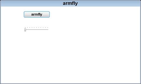
The interface can be displayed, which only means that the display driver is OK, and the touch has to be tested. This example has enabled the cursor display. Users can slide horizontally or vertically on the interface to see how the cursor moves. If they can move with their hands, it means that there is no problem with touching. If not, it should be analyzed in two cases:
- Touch calibration is required for the resistance screen. See the instructions in Annex A in Chapter 66 of the tutorial for the calibration method. In addition, if this is designed by ourselves, it is necessary to check whether there are problems in the hardware design of the code and touch pad.
- Since the capacitive screen is automatically touch calibrated, in this case, it is necessary to check the code and the hardware design of the touch panel.
The following is the test code written. The complete version of the supporting test example is V7-505_emWin6.x experiment_ Porting templates in RTOS mode.
Experiment content:
- Press the K1 key, and the serial port print task execution (baud rate 115200, data bit 8, parity bit none, stop bit 1).
- The functions of each task are as follows:
App Task Start task: realize key press and touch scanning.
App Task MspPro task: not used yet.
App task: key message processing.
App Task COM} task: not used yet.
App task: GUI task.
μ COS-III task debugging information (press K1 key and print through serial port):
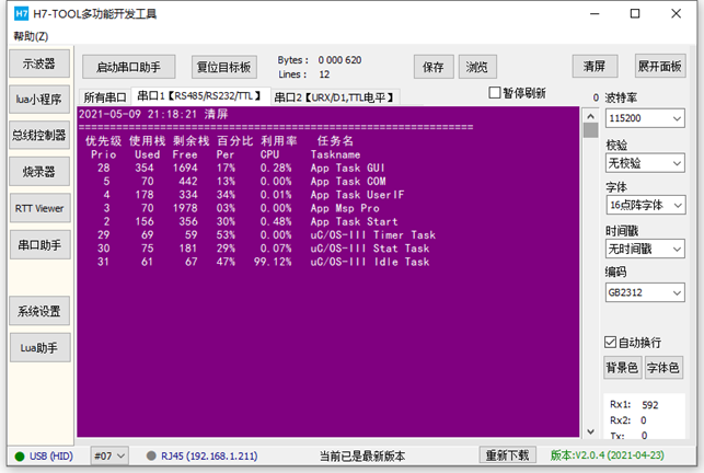
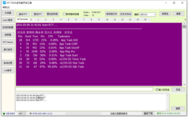
RTT printing information mode:
Programming:
Task stack size allocation:
- μ COS-III task stack size in app_ cfg. Configuration in H file:
#define APP_CFG_TASK_START_STK_SIZE 512u
#define APP_CFG_TASK_MsgPro_STK_SIZE 2048u
#define APP_CFG_TASK_COM_STK_SIZE 512u
#define APP_CFG_TASK_USER_IF_STK_SIZE 512u
#define APP_CFG_TASK_GUI_STK_SIZE 2048u
- The unit of task stack size is 4 bytes, so the stack size of each task is as follows:
App Task Start: 2048 bytes.
App Task MspPro task: 8192 bytes.
App task: 2048 bytes.
App Task COM} task: 2048 bytes.
App Task GUI task: 8192 bytes.
System stack size allocation:
μ The system stack size of COS-III is in OS_ cfg_ app. Configuration in H file:
#define OS_CFG_ISR_STK_SIZE 512u
The unit of system stack size is 4 bytes, so here is to configure the system stack size to 2KB
μ COS-III initialization:
/*
*********************************************************************************************************
*    Function name: main
*    Function Description: standard c program entry.
*    Formal parameter: None
*    Return value: None
*********************************************************************************************************
*/
int main(void)
{
    OS_ERR  err;

    /* Initialize uC/OS-III kernel */
    OSInit(&err);

    /* Create a startup task (that is, the main task). Starting a task creates all application tasks */
    OSTaskCreate((OS_TCB       *)&AppTaskStartTCB,  /* Task control block address */
                 (CPU_CHAR     *)"App Task Start",  /* Task name */
                 (OS_TASK_PTR   )AppTaskStart,      /* Start task function address */
                 (void         *)0,                 /* Parameters passed to the task */
                 (OS_PRIO       )APP_CFG_TASK_START_PRIO, /* Task priority */
                 (CPU_STK      *)&AppTaskStartStk[0],     /* Stack base address */
                 (CPU_STK_SIZE  )APP_CFG_TASK_START_STK_SIZE / 10, /* Stack monitoring area, where the last 10% is used as the monitoring area */
                 (CPU_STK_SIZE  )APP_CFG_TASK_START_STK_SIZE,      /* Stack space size */
                 (OS_MSG_QTY    )0,  /* The maximum number of messages accepted by this task */
                 (OS_TICK       )0,  /* Set time slice */
                 (void         *)0,  /* Stack space size */
                 (OS_OPT        )(OS_OPT_TASK_STK_CHK | OS_OPT_TASK_STK_CLR),

                 /*  It is defined as follows:
                    OS_OPT_TASK_STK_CHK      Enable to detect the task stack and count the used and unused tasks of the task stack
                    OS_OPT_TASK_STK_CLR      Clear the task stack when creating a task
                    OS_OPT_TASK_SAVE_FP      If the CPU has a floating-point register, the contents of the floating-point register are saved during task switching
                 */
                 (OS_ERR       *)&err);

    /* Start the multitasking system and give control to uC/OS-III */
    OSStart(&err);

    (void)&err;

    return (0);
}

int main(void)
{
    OS_ERR  err;

    /* HAL Library, MPU, Cache, clock and other system initialization */
    System_Init();

    /* Time benchmark for closing HAL before kernel startup */
    HAL_SuspendTick();

    /* Initialize the tick clock and start it in the startup task */
    BSP_OS_TickInit();

    /* Initialize uC/OS-III kernel */
    OSInit(&err);

    /* Create a startup task (that is, the main task). Starting a task creates all application tasks */
    OSTaskCreate((OS_TCB       *)&AppTaskStartTCB,  /* Task control block address */
                 (CPU_CHAR     *)"App Task Start",  /* Task name */
                 (OS_TASK_PTR   )AppTaskStart,      /* Start task function address */
                 (void         *)0,                 /* Parameters passed to the task */
                 (OS_PRIO       )APP_CFG_TASK_START_PRIO, /* Task priority */
                 (CPU_STK      *)&AppTaskStartStk[0],     /* Stack base address */
                 (CPU_STK_SIZE  )APP_CFG_TASK_START_STK_SIZE / 10, /* Stack monitoring area, where the last 10% is used as the monitoring area */
                 (CPU_STK_SIZE  )APP_CFG_TASK_START_STK_SIZE,      /* Stack space size */
                 (OS_MSG_QTY    )0,  /* The maximum number of messages accepted by this task */
                 (OS_TICK       )0,  /* Set time slice */
                 (void         *)0,  /* Stack space size */
                 (OS_OPT        )(OS_OPT_TASK_STK_CHK | OS_OPT_TASK_STK_CLR),

                 /*  It is defined as follows:
                    OS_OPT_TASK_STK_CHK      Enable to detect the task stack and count the used and unused tasks of the task stack
                    OS_OPT_TASK_STK_CLR      Clear the task stack when creating a task
                    OS_OPT_TASK_SAVE_FP      If the CPU has a floating-point register, the contents of the floating-point register are saved during task switching
                 */
                 (OS_ERR       *)&err);

    /* Start the multitasking system and give control to uC/OS-III */
    OSStart(&err);

    (void)&err;

    return (0);
}
Hardware peripheral initialization
The initialization of hardware peripherals is in BSP C file realization:
/*
*********************************************************************************************************
*    Function name: System_Init
*    Function Description: system initialization, mainly including MPU, Cache and system clock configuration
*    Formal parameter: None
*    Return value: None
*********************************************************************************************************
*/
void System_Init(void)
{

    /* Configure MPU */
    MPU_Config();

    /* Enable L1 Cache */
    CPU_CACHE_Enable();

    /*
       STM32H7xx HAL When the library is initialized, the system still uses the 64MHz provided by H7. HSI clock:
       - Call function HAL_InitTick, initialize tick clock interrupt for 1ms.
       - Set the NVIC priority group to 4.
     */
    HAL_Init();

    /*
       Configure the system clock to 400MHz
       - Switch to HSE.
       - This function updates the global variable systemcorelock and reconfigures HAL_InitTick.
    */
    SystemClock_Config();

    /*
       Event Recorder:
       - It can be used for code execution time measurement, mdk5 25 and above, not IAR.
       - It is not enabled by default. If you want to enable this option, please refer to Chapter 8 of the V7 development board user manual
    */
#if Enable_EventRecorder == 1
    /* Initialize the EventRecorder and turn it on */
    EventRecorderInitialize(EventRecordAll, 1U);
    EventRecorderStart();
#endif

#if Enable_RTTViewer == 1
    /* Configure channel 0, uplink configuration*/
    SEGGER_RTT_ConfigUpBuffer(0, "RTTUP", NULL, 0, SEGGER_RTT_MODE_NO_BLOCK_SKIP);

    /* Configure channel 0, downlink configuration*/
    SEGGER_RTT_ConfigDownBuffer(0, "RTTDOWN", NULL, 0, SEGGER_RTT_MODE_NO_BLOCK_SKIP);
#endif
}

/*
*********************************************************************************************************
*    Function name: bsp_Init
*    Function Description: initialize all hardware devices. This function configures CPU registers and peripheral registers and initializes some global variables. It only needs to be called once
*    Formal parameter: None
*    Return value: None
*********************************************************************************************************
*/
void bsp_Init(void)
{
    bsp_InitKey();        /* The key initialization should be placed before the tick timer, because the button detection is scanned by the tick timer */
    bsp_InitTimer();      /* Initialize tick timer */
    bsp_InitUart();        /* Initialize serial port */
    bsp_InitExtIO();    /* Initialize FMC bus 74HC574 extension IO Must be in BSP_ Execute before initled() */
    bsp_InitLed();        /* Initialize LED */
    bsp_InitExtSDRAM(); /* Initialize SDRAM */

    bsp_InitI2C();        /* Initialize I2C bus */
    TOUCH_InitHard();   /* Initialize the touch chip and check the LCD panel model in this function, so it is necessary to check the LCD panel model in the function_ InitHard prior call */

    /* Delay 200ms to turn on the backlight again to avoid instant highlight */
//    bsp_DelayMS(200);
//    LCD_SetBackLight(255);
}
Five μ Implementation of COS-III tasks:
/*
*********************************************************************************************************
*    Function name: AppTaskStart
*    Function Description: This is a start task. After the multi task system is started, the tick counter must be initialized. This task mainly realizes key detection.
*    Formal parameter: p_arg is the formal parameter passed when the task is created
*    Return value: None
    Priority: 2
*********************************************************************************************************
*/
static  void  AppTaskStart (void *p_arg)
{
    OS_ERR      err;

   (void)p_arg;

    HAL_ResumeTick();

    CPU_Init(); /* This function should be called first because the us and ms delays used in peripheral drivers are based on this function */
     bsp_Init();
    BSP_OS_TickEnable();

#if OS_CFG_STAT_TASK_EN > 0u
     OSStatTaskCPUUsageInit(&err);
#endif

#ifdef CPU_CFG_INT_DIS_MEAS_EN
    CPU_IntDisMeasMaxCurReset();
#endif

    /* Create task */
    AppTaskCreate();

    /* Create inter task communication mechanism */
    AppObjCreate();

    while (1)
    {
        /* Programs that need periodic processing correspond to systick called by bare metal projects_ ISR */
        bsp_ProPer1ms();
        OSTimeDly(1, OS_OPT_TIME_PERIODIC, &err);
    }
}

/*
*********************************************************************************************************
*    Function name: AppTaskMsgPro
*    Function Description: message processing, used here as LED flashing
*    Formal parameter: p_arg is the formal parameter passed when the task is created
*    Return value: None
    Priority: 3
*********************************************************************************************************
*/
static void AppTaskMsgPro(void *p_arg)
{
    OS_ERR  err;

    (void)p_arg;

    while(1)
    {
        bsp_LedToggle(2);
        OSTimeDly(200, OS_OPT_TIME_DLY, &err);
    }
}

/*
*********************************************************************************************************
*    Function name: AppTaskUserIF
*    Function Description: key message processing
*    Formal parameter: p_arg is the formal parameter passed when the task is created
*    Return value: None
    Priority: 4
*********************************************************************************************************
*/
static void AppTaskUserIF(void *p_arg)
{
    OS_ERR  err;
    uint8_t ucKeyCode;    /* Key code */

    (void)p_arg;

    while(1)
    {
        ucKeyCode = bsp_GetKey();

        if (ucKeyCode != KEY_NONE)
        {
            switch (ucKeyCode)
            {
                case KEY_DOWN_K1:              /* K1 Press the key to print the execution of the task */
                    DispTaskInfo();
                    break;

                default:                     /* Other key values are not processed */
                    break;
            }
        }

        OSTimeDly(20, OS_OPT_TIME_DLY, &err);
    }
}

/*
*********************************************************************************************************
*    Function name: AppTaskCom
*    Function Description: not used yet
*    Formal parameter: p_arg is the formal parameter passed when the task is created
*    Return value: None
    Priority: 5
*********************************************************************************************************
*/
static void AppTaskCOM(void *p_arg)
{
    OS_ERR  err;

    (void)p_arg;

    while(1)
    {
        OSTimeDly(1000, OS_OPT_TIME_DLY, &err);
    }
}

/*
*********************************************************************************************************
*    Function name: AppTaskGUI
*    Function Description: GUI task, lowest priority
*    Formal parameter: p_arg is the formal parameter passed when the task is created
*    Return value: None
*   Priority: OS_CFG_PRIO_MAX - 4u
*********************************************************************************************************
*/
static void AppTaskGUI(void *p_arg)
{
    (void)p_arg;        /* Avoid compiler alarms */

    while (1)
    {
        MainTask();
    }
}
Specific implementation of emWin task (in MainTask.c file):
#include "includes.h"
#include "MainTask.h"


/*
*********************************************************************************************************
*                           GUI_WIDGET_CREATE_INFO Type array
*********************************************************************************************************
*/
static const GUI_WIDGET_CREATE_INFO _aDialogCreate[] = {
    { FRAMEWIN_CreateIndirect,  "armfly",            0,           0,  0,  480,272,FRAMEWIN_CF_MOVEABLE,0},
    { BUTTON_CreateIndirect,    "BUTTON0",           GUI_ID_BUTTON0,          29, 20, 200,50, 0,0},
    { SLIDER_CreateIndirect,     NULL,               GUI_ID_SLIDER0,          29, 143,218,40, 0,0}
};

/*
*********************************************************************************************************
*    Function name: PaintDialog
*    Function Description: WM of dialog box callback function_ Paint message processing
*    Formal parameter: pMsg callback parameter
*    Return value: None
*********************************************************************************************************
*/
void PaintDialog(WM_MESSAGE * pMsg)
{
    //WM_HWIN hWin = pMsg->hWin;

}

/*
*********************************************************************************************************
*    Function name: InitDialog
*    Function Description: WM of dialog box callback function_ INIT_ Dialog message processing
*    Formal parameter: pMsg callback parameter
*    Return value: None
*********************************************************************************************************
*/
void InitDialog(WM_MESSAGE * pMsg)
{
    WM_HWIN hWin = pMsg->hWin;
    WM_HWIN hItem;

    //
    //FRAMEWIN
    //
    FRAMEWIN_SetFont(hWin,&GUI_Font32B_ASCII);
    FRAMEWIN_AddCloseButton(hWin, FRAMEWIN_BUTTON_RIGHT, 0);
    FRAMEWIN_AddMaxButton(hWin, FRAMEWIN_BUTTON_RIGHT, 1);
    FRAMEWIN_AddMinButton(hWin, FRAMEWIN_BUTTON_RIGHT, 2);
    FRAMEWIN_SetTitleHeight(hWin,32);


    hItem = WM_GetDialogItem(pMsg->hWin, GUI_ID_BUTTON0);
    BUTTON_SetFont(hItem, GUI_FONT_16_1);
}

/*
*********************************************************************************************************
*    Function name:_ cbCallback
*    Function Description: dialog box callback function
*    Formal parameter: pMsg callback parameter
*    Return value: None
*********************************************************************************************************
*/
static void _cbCallback(WM_MESSAGE * pMsg)
{
    int NCode, Id;
    WM_HWIN hWin = pMsg->hWin;

    switch (pMsg->MsgId)
    {
        case WM_PAINT:
            PaintDialog(pMsg);
            break;

        case WM_INIT_DIALOG:
            InitDialog(pMsg);
            break;

        case WM_KEY:
            switch (((WM_KEY_INFO*)(pMsg->Data.p))->Key)
            {
                case GUI_KEY_ESCAPE:
                    GUI_EndDialog(hWin, 1);
                    break;
                case GUI_KEY_ENTER:
                    GUI_EndDialog(hWin, 0);
                    break;
            }
            break;

        case WM_NOTIFY_PARENT:
            Id = WM_GetId(pMsg->hWinSrc);
            NCode = pMsg->Data.v;
            switch (Id)
            {
                case GUI_ID_OK:
                    if(NCode==WM_NOTIFICATION_RELEASED)
                        GUI_EndDialog(hWin, 0);
                    break;
                case GUI_ID_CANCEL:
                    if(NCode==WM_NOTIFICATION_RELEASED)
                        GUI_EndDialog(hWin, 0);
                    break;

            }
            break;

        default:
            WM_DefaultProc(pMsg);
    }
}

/*
*********************************************************************************************************
*    Function name: MainTask
*    Function Description: GUI main function
*    Formal parameter: None
*    Return value: None
*********************************************************************************************************
*/
void MainTask(void)
{

    /* initialization */
    GUI_Init();

    /*
     Setting instructions for multi buffer and window memory devices
       1. Enable multi buffer is the following function called by the user in LCDConf_Lin_Template.c file is configured with multiple buffers. Only when this function is called can it be effective:
          WM_MULTIBUF_Enable(1);
       2. Window enable memory device is calling function: WM_SetCreateFlags(WM_CF_MEMDEV);
       3. If the configuration of emWin supports both multi buffer and window memory devices, choose one from two, and be sure to give priority to the use of multi buffer for actual use
          STM32H7 + 32 Bit SDRAM + RGB565/RGB888 platform test, multi buffer can effectively reduce the tear when the window moves or slides
          And effectively improve the fluency. It is impossible to use the memory device through the enabling window.
       4. By default, all emWin examples enable triple buffering.
    */
    WM_MULTIBUF_Enable(1);

    /*
       The touch calibration function is commented out by default. The resistance screen needs calibration and the capacitance screen does not need calibration. If the user needs to calibrate the resistance screen, execute
       This function can save the touch calibration parameters into EEPROM, and the system will automatically load them from EEPROM after power on.
    */
#if 0
    LCD_SetBackLight(255);
    TOUCH_Calibration(2);
#endif

    /* Set the background color of the desktop window to white and support redrawing */
    WM_SetDesktopColor(GUI_BLUE);

    /* create a dialog box */
    GUI_CreateDialogBox(_aDialogCreate, GUI_COUNTOF(_aDialogCreate), &_cbCallback, 0, 0, 0);

    /* Light up after the screen is displayed to effectively prevent instant highlighting */
    GUI_Delay(200);
    LCD_SetBackLight(255);

    while(1)
    {
        GUI_Delay(10);
    }
}
8.11 solution to flicker of display screen
If you are debugging or just download the emWin program to STM32H7/STM32F429, the screen will flash or shake, which is a normal phenomenon. See the instructions on this post for details:
http://www.armbbs.cn/forum.php?mod=viewthread&tid=16892 .
If the display is in the jitter state for a long time, it indicates that the LTDC clock configuration is high or low (most of the high probability). You can reduce the LTDC clock by half or double for testing. See section 4.4.3 in Chapter 4 of this tutorial for the configuration method.
8.12 avoid highlighting and tearing of the display screen at the moment of power on
When you use the display screen, these two problems are easy to encounter. Here is a solution to improve the user experience.
This problem is not caused by software configuration, and it cannot be solved by adjusting PWM backlight. The solution is not to turn on the PWM after it is on the board, and then turn on the backlight of the LCD after a delay of 200ms. Note that the time cannot be too short, which has no effect. You can adjust it according to the actual situation.
Sometimes, when the interface design is complex, it can't ensure that all controls are loaded at the same time after startup, and the interface will feel torn. At this time, there is a better solution. Turn off the backlight before emWin initialization configuration, turn on the backlight after initialization and the first interface drawing, and the user experience will be much better.
The supporting procedures in this chapter are placed in MainTask The function MainTask of C file is processed.
/*
*********************************************************************************************************
*    Function name: MainTask
*    Function Description: GUI main function
*    Formal parameter: None
*    Return value: None
*********************************************************************************************************
*/
void MainTask(void)
{

    Omit unwritten

Interface initialization

    /* Light up after the screen is displayed to effectively prevent instant highlight and tear feeling */
    GUI_Delay(200);
LCD_SetBackLight(255);
}
8.13 experimental routine
(Note: if it is A resistive screen, touch calibration is required. See chapter A of the annex to this tutorial for the calibration method)
This chapter provides the following examples for your reference:
- V7-505_emWin6.x experiment_ RTOS mode migration template
RTOS mode template is used for the reference Demo of transplanting emWin.
8.14 summary
The content explained in this chapter involves a lot of knowledge and a large amount of information. It doesn't matter if some knowledge points are not understood, but it must be transplanted according to the transplantation method provided in this chapter. In addition, it is better to transplant a display screen and touch IC different from the tutorial supporting development board, so that the understanding of this chapter will be more comprehensive.