-
modbus protocol
After completing the programming of modbus protocol, the device can be tested as the master or slave of modbus protocol. After the test with simulation software, the complete code is introduced in the form of three versions
1. Version 1: use the serial port to receive data timeout to complete the receiving of data (STM32 Standard Library)
2. Version 2: advanced version - use DMA to send and receive data (STM32 Standard Library)
3. Version 3: modify the above code by using HAL library for the first time (STM32HAL Library)
1, modbus protocol preparation
modbus poll and modbus slave simulation software download (download can be used directly)
modbus protocol auxiliary software download - Baidu network disk link extraction code: 8g9c
modbus simulation software usage - Reference blog link
The up Master of station b uploaded three related videos
-
Video 1
The explanation is very detailed and can be read carefully. The explanation includes the use of simulation software and the writing of some codes. It is much easier to understand and write codes - strongly recommended
-
Video 2
The total time is one hour and forty minutes. I watched it for one hour without any substantive explanation (I can't watch it). I didn't get to the point until one hour. After watching it for a few minutes, I didn't have the patience to watch it and closed it directly
-
Video 3
I didn't see the third video. I don't know what it said
The up master is recorded casually. Although there are some defects, it is a good resource and is very helpful for the learning of modbus. Thank you for sharing.

-
modbus protocol
The basic knowledge of modbus protocol will not be repeated. For details, click the following link
Modbus RTU protocol Usage Summary - modbus protocol reference blog link 1
MODBUS_RTU communication protocol - modbus protocol reference blog link 2
2, modbus Protocol Software analog communication
-
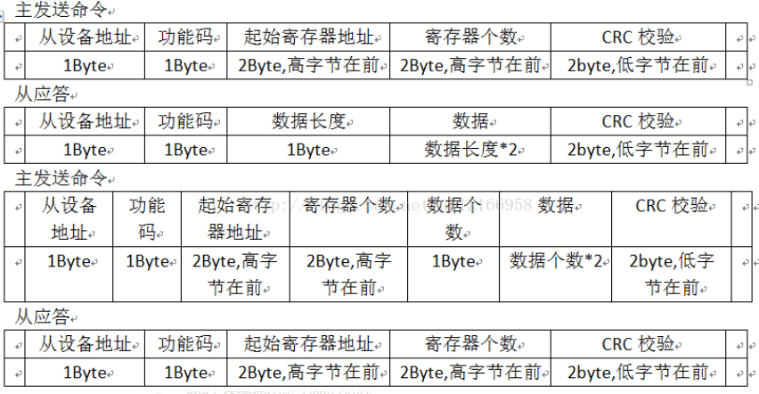
Data protocol format
-
Function code 0x03 – read data from slave register
! [insert here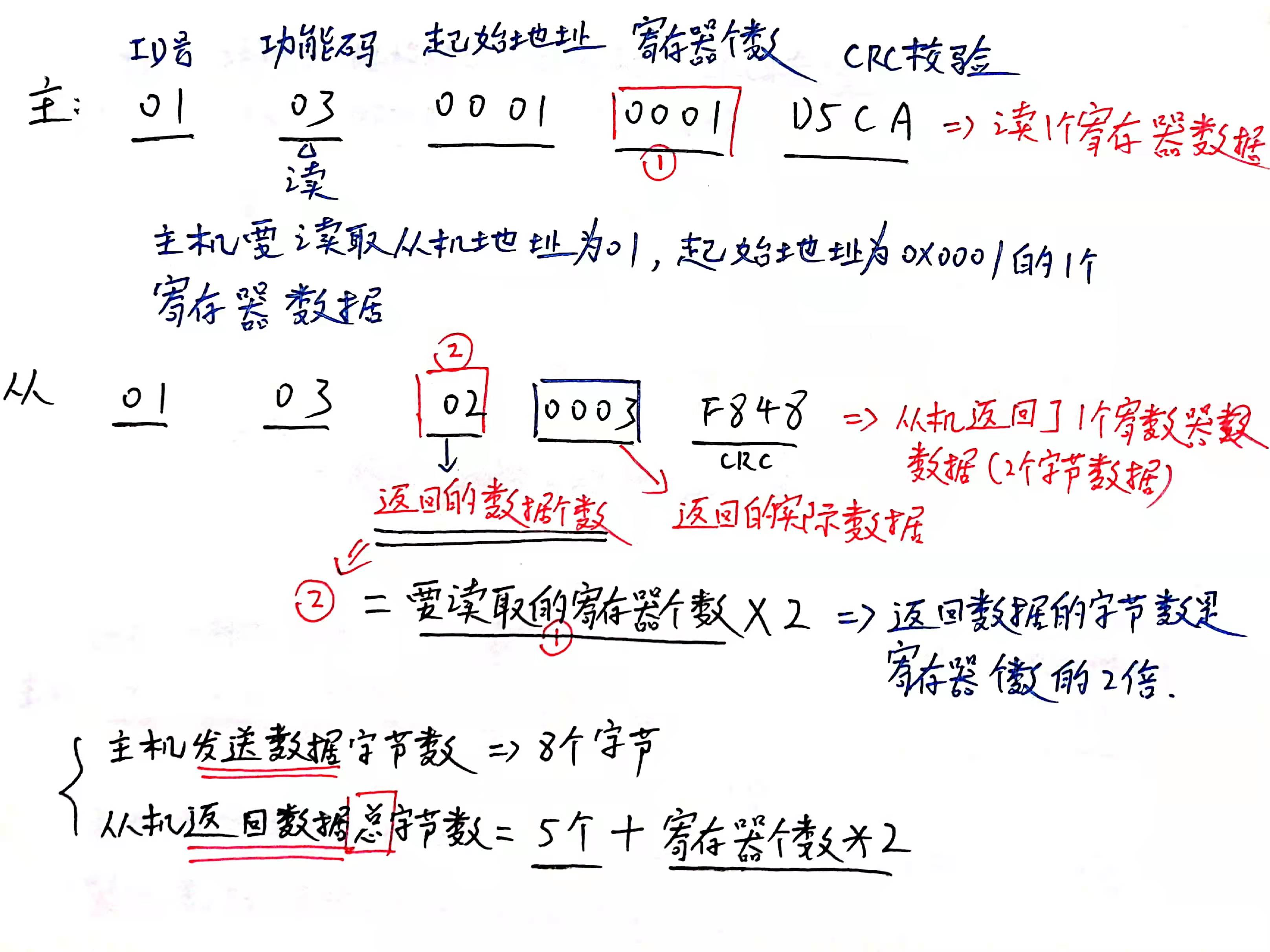
-
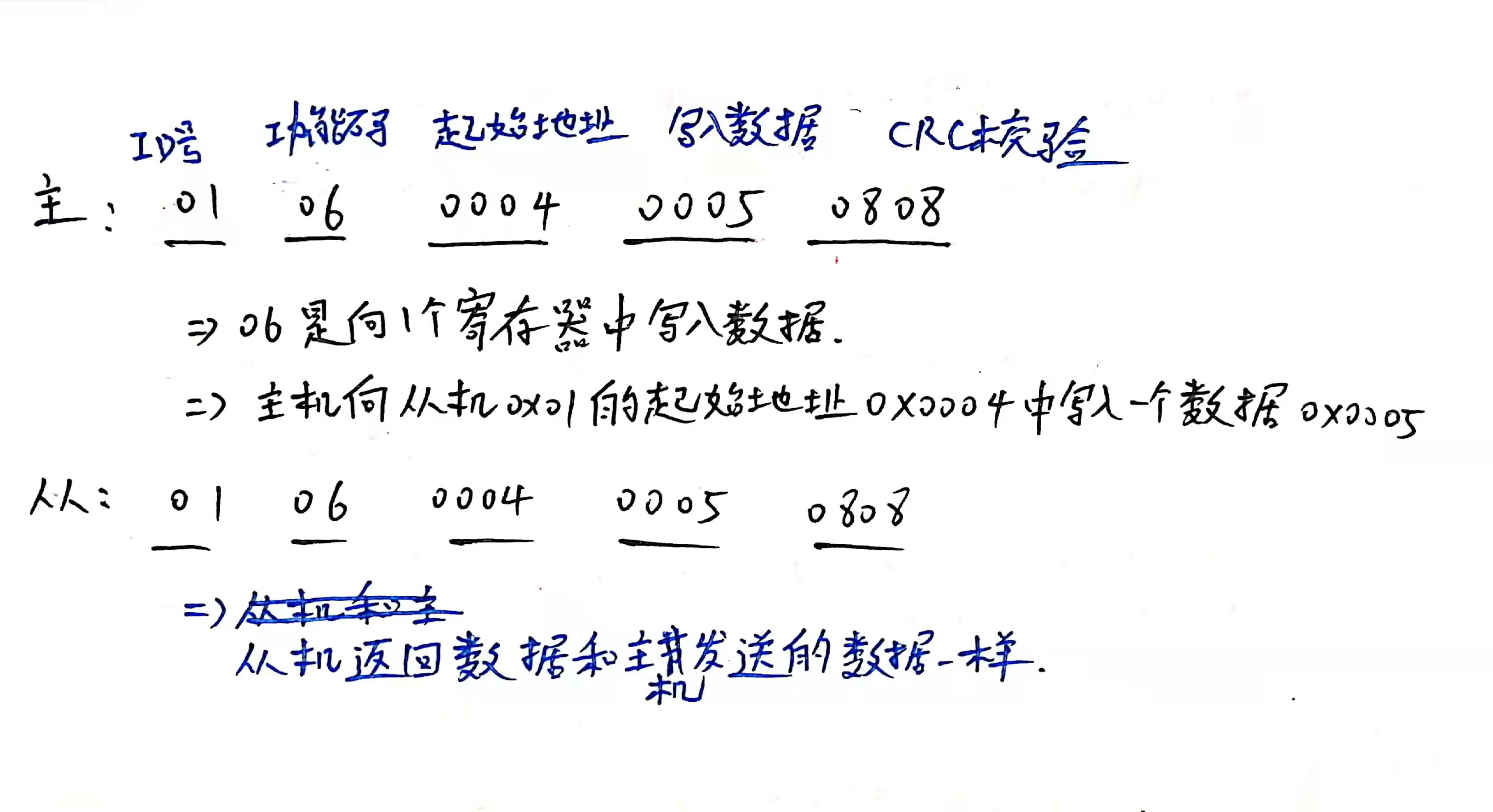
Function code 0x06 – write data to a register

-
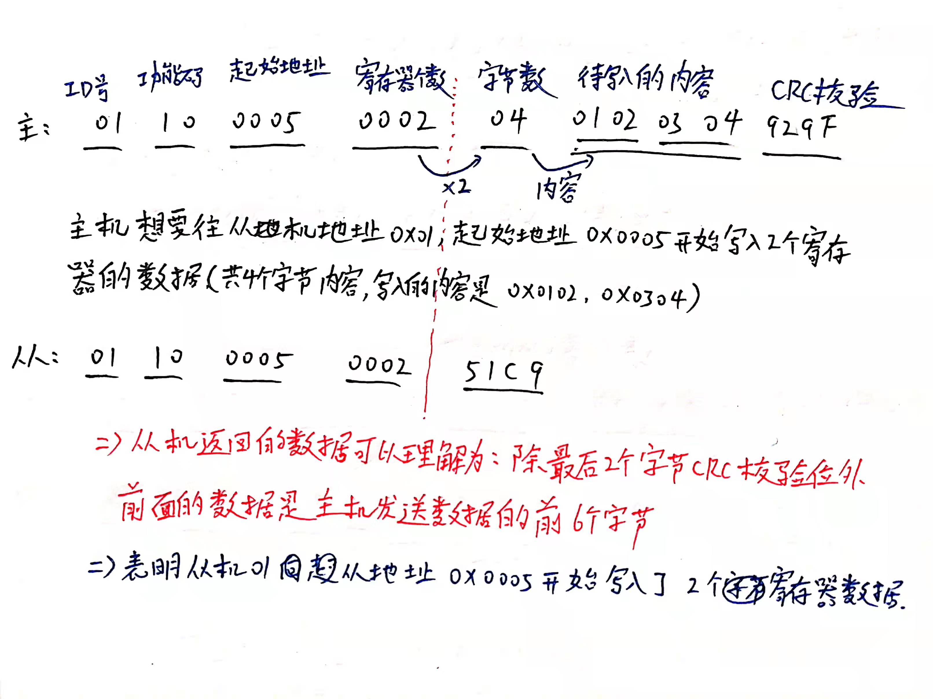
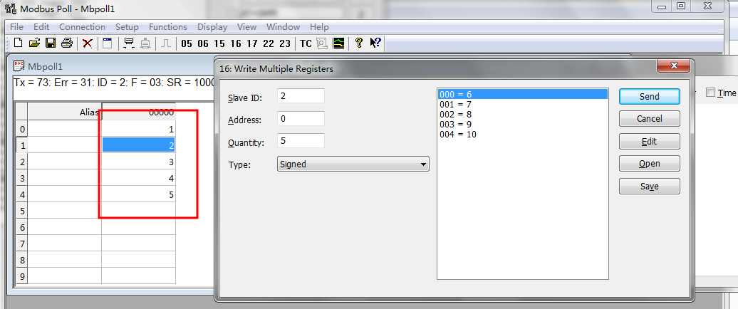
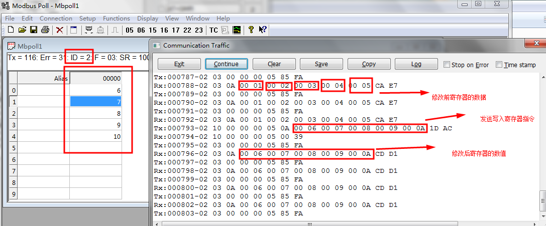
Function code 0x10 - write data to multiple registers

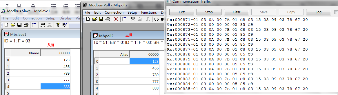
(1) Use modbus poll (Master) and modbus slave (slave) for simulation
1. The host can read the data from the slave
2. After the slave modifies the data, the host will update the data
3. The host modifies the value of an address and updates it accordingly from the host
(2) Use serial port assistant (host) and modbus slave software (slave)
-
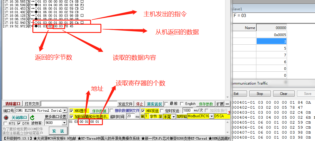
The master reads the data of one register from the slave
The master uses function code 03 to read a register data with slave address 01 and starting address 0x0001
-
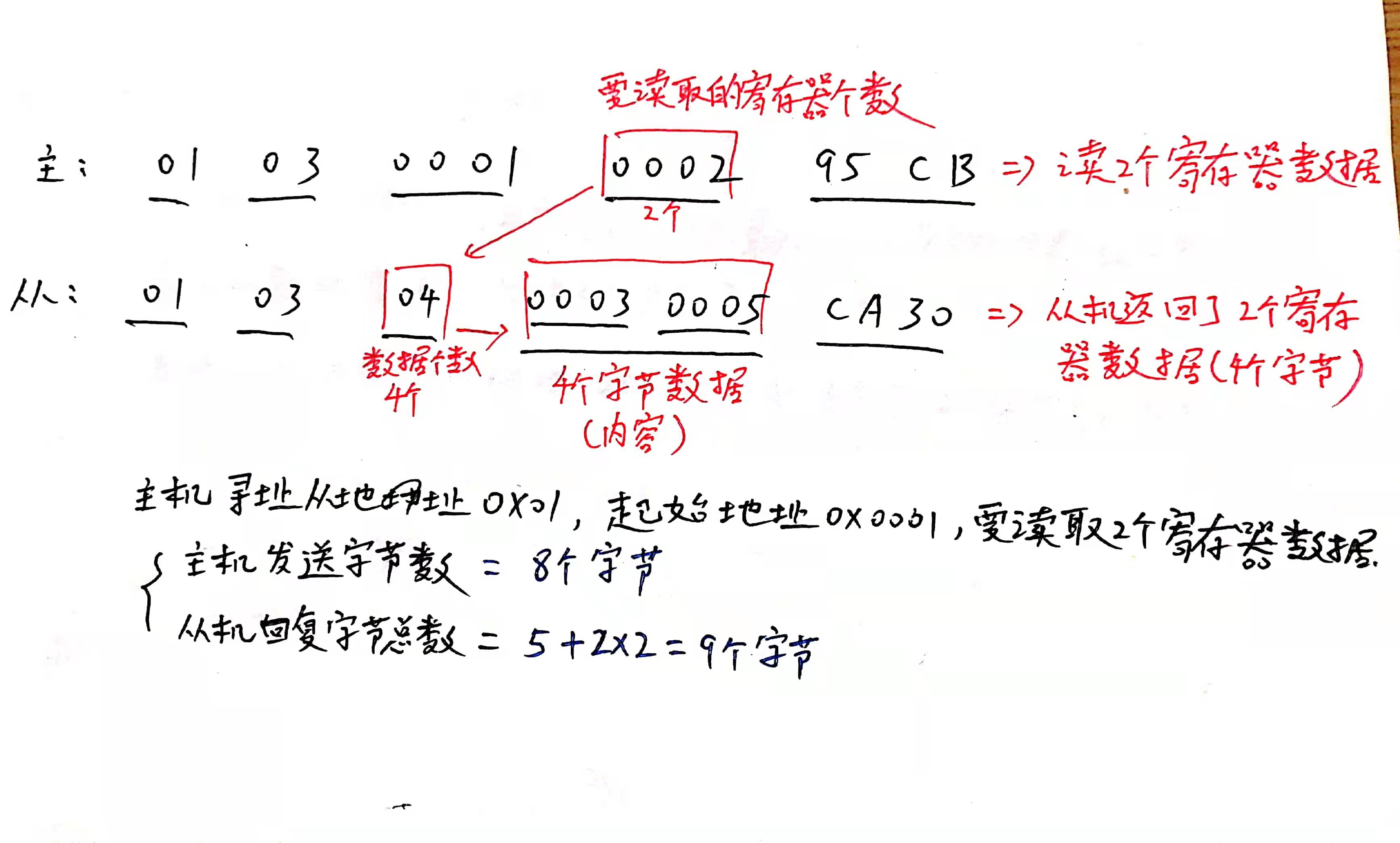
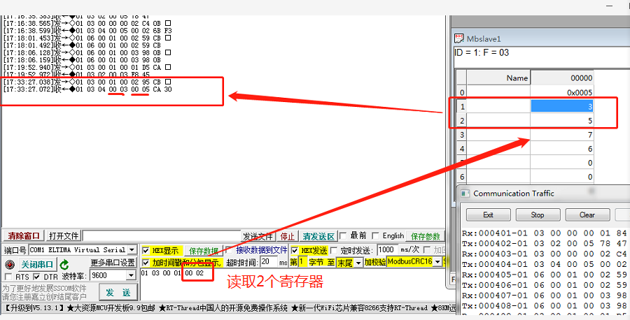
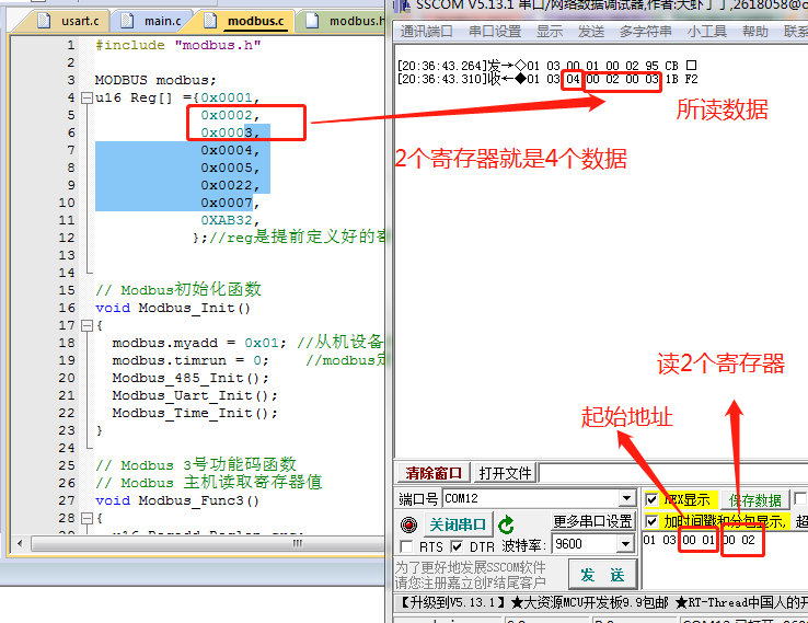
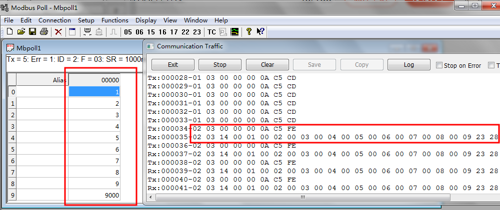
The master reads the data of two registers from the slave
Two register data with slave address 0x01 and starting address 0x0001
-
The master writes data to one register of the slave
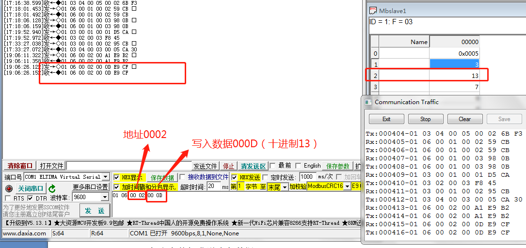
Host sends command 01 06 00 02 00 0D
Write data 000D to address 0002 -
The master writes data to multiple registers of the slave
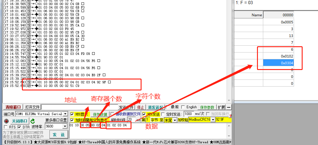
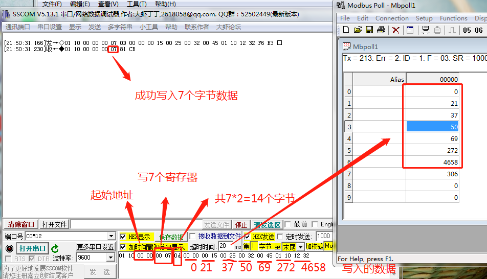
01 10 00 05 00 02 04 01 02 03 04 92 9F
Send two registers and four bytes of data from 00 05 address, and the data is 01 02 03 04 respectively
(3) Serial assistant (host) and STM32 (slave)
- Read two register data
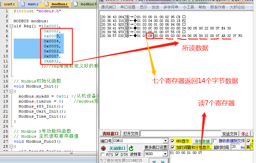
- Read 7 register data
-
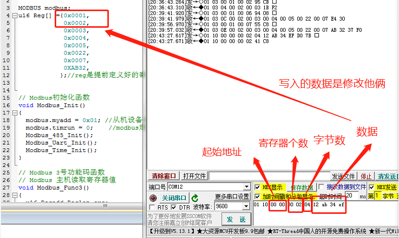
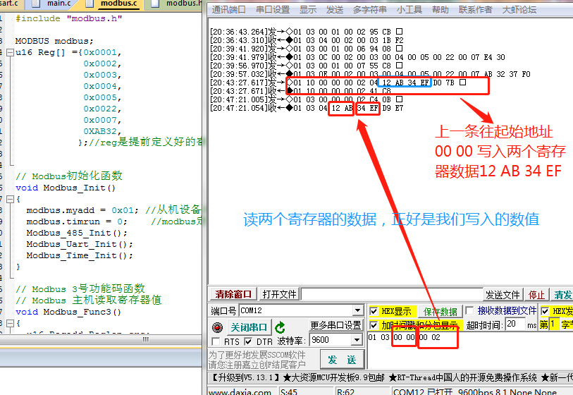
Write two register data
Write the value of the first and second elements and read the value of the register
-
Write data in 7 registers
First, use the serial port assistant to write values to 7 registers. After closing the serial port, use the modbus poll software to read the values
3, modbus protocol programming - device as host
-
Define a structure: (it will be used when the device is used as a master or slave)
 typedef struct
 {
 	//Used as a slave
  	 u8  myadd;        //Slave address of this device
 	u8  rcbuf[100];   //modbus accept buffer
 	u8  timout;       //modbus data duration
 	u8  recount;      //Number of data received by modbus port
 	u8  timrun;       //Timing flag of modbus timer
 	u8  reflag;       //modbus one frame data acceptance completion flag bit
 	u8  sendbuf[100]; //modbus connection and transmission buffer

 	//Add as part of host
 	u8 Host_Txbuf[8];	//modbus send array
 	u8 slave_add;		//Slave device address to match (used in host experiment)
 	u8 Host_send_flag;//Host device sending data completion flag bit
 	int Host_Sendtime;//Time count after sending one frame of data
 	u8 Host_time_flag;//When the sending time reaches the flag bit, = 1 indicates that it is time to send data
 	u8 Host_End;//After receiving the data, the processing is completed
 }MODBUS;
If it is used in HAL library, replace u8 with uint8_t is enough
(1) Function code 0x03 - the master reads the register data of the slave
First, let's take a look at the format of the data sent by the host and the data sent by the slave, as well as the corresponding meaning of each part

When the master addresses the slave, it sends a total of 8 bytes of data (slave address ID number 1 byte, function code 1 byte, starting address 2 bytes, number of registers 2 bytes, CRC check bit 2 bytes)

It's easier to write the register data read from the host addressing slave - that is, fill in the contents of an 8-byte array, and then send the data through the serial port
First of all, we need a slave address, then the function number (write 0X03 directly), as well as the starting address, the number of registers read, and CRC check bits (calculated independently by the function), so we only need three parameters
-
1 - Master addressing slave reading register data (function code 0x03)
Parameter 1 slave address (1 byte) – slave to be addressed
Parameter 2 start address (2 bytes) – the address at which data reading starts
Parameter 3 number of registers (2 bytes) – number of registers to be read//Parameter 1 slave address, parameter 2 start address, parameter 3 number of registers void Host_Read03_slave(uint8_t slave,uint16_t StartAddr,uint16_t num) { int j; uint16_t crc;//Calculated CRC check bit modbus.slave_add=slave;//This is to store the slave address first, which will be used later when receiving data processing modbus.Host_Txbuf[0]=slave;//This is the slave address to match modbus.Host_Txbuf[1]=0x03;//Function code modbus.Host_Txbuf[2]=StartAddr/256;//Start address high order modbus.Host_Txbuf[3]=StartAddr%256;//Start address low order modbus.Host_Txbuf[4]=num/256;//Number of registers high order modbus.Host_Txbuf[5]=num%256;//Number of registers low order crc=Modbus_CRC16(&modbus.Host_Txbuf[0],6); //Get CRC check bit modbus.Host_Txbuf[6]=crc/256;//Number of registers high order modbus.Host_Txbuf[7]=crc%256;//Number of registers low order //Sending data packaging completed (8 bytes in total) //Start sending data RS485_TX_ENABLE;//Enable 485 control terminal (start sending) for(j=0;j<i;j++) { Modbus_Send_Byte(modbus.sendbuf[j]); } RS485_RX_ENABLE;//Disable 485 control terminal (change to receive) } -
2 - processing of data returned by the master to the slave:
(1) First, we need to judge whether the data has been received. Only when the data has been received can we process the data (modbus.reflag==1 indicates that the data has been received), and then go to the next step.
(2) After the data is received, we need to compare the self calculated CRC check bit with the received CRC check bit to see whether they are consistent. If they are consistent, it indicates that the data is received correctly and proceed to the next step.
(3) After judging the CRC check bit, judge whether it is the data returned by the slave addressed by the host. If it meets the conditions, proceed to the next step.
(4) If the above conditions are met, process the received data: extract the useful data from the returned data for serial port printing or other purposes//The host receives the message from the slave and processes it. The function code is 0x03 void HOST_ModbusRX() { u16 crc,rccrc;//Calculate crc and received crc if(modbus.reflag == 0) //If the reception is not completed, null is returned { return; } //End of receiving data //(all but the last two CRC check bits in the array are counted) crc = Modbus_CRC16(&modbus.rcbuf[0],modbus.recount-2); //Get CRC check bit rccrc = modbus.rcbuf[modbus.recount-2]*256+modbus.rcbuf[modbus.recount-1];//Calculate the CRC check bit read if(crc == rccrc) //CRC inspection successfully started analysis package { if(modbus.rcbuf[0] == modbus.slave_add) // Check that the address is sent from the corresponding machine { if(modbus.rcbuf[1]==3)//Function code 03 Host_Func3();//This is to read the valid data bits of the register for calculation } } modbus.recount = 0;//Receive count reset modbus.reflag = 0; //Receive flag reset } -
3 - real data processing function void Host_Func3()
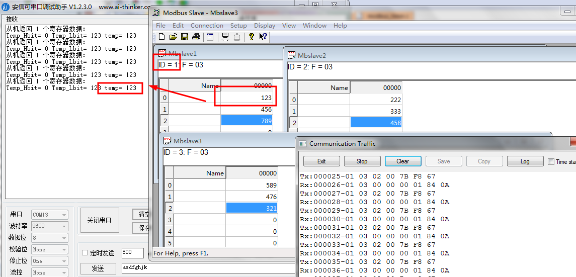
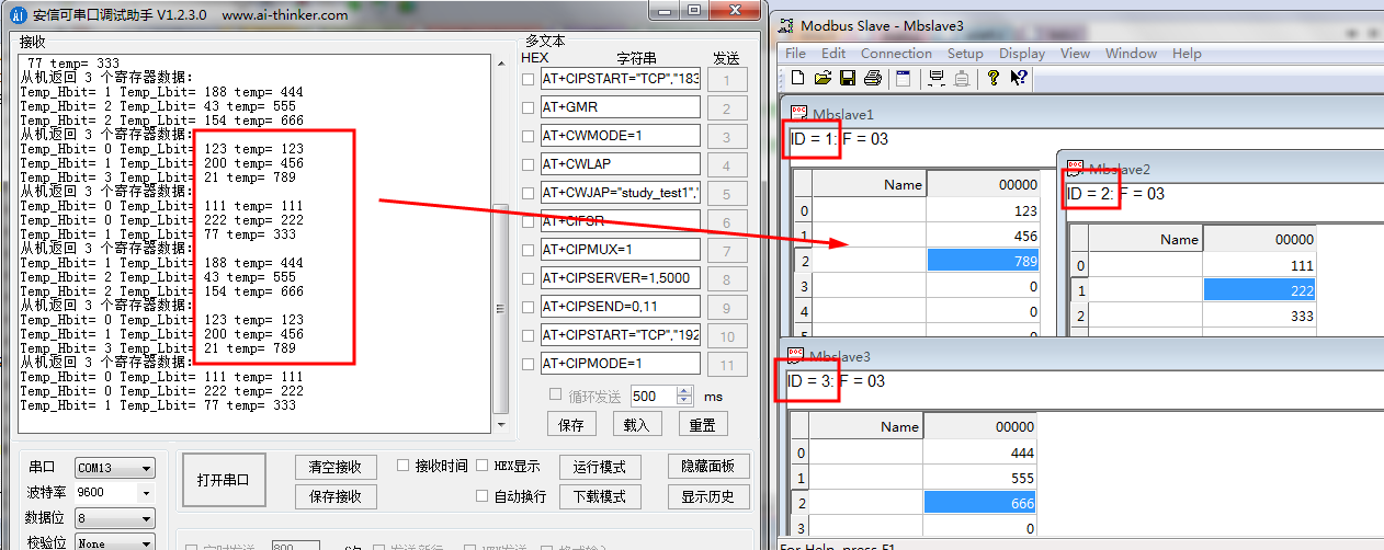
Through the previous analysis of the format of the data returned from the slave, we can see that the third byte (corresponding to modbus.rcbuf[2] bit) in the data is the effective number of the returned data, and the effective content of the data starts from the fourth byte. A register data is divided into high and low bits, and all two bytes are a complete data, which can be calculated.
 void Host_Func3()
 {
 	int i;
 	int count=(int)modbus.rcbuf[2];//This is the number of data

 	printf("Slave return %d Register data:\r\n",count/2);
 	for(i=0;i<count;i=i+2)
 	{
 		printf("Temp_Hbit= %d Temp_Lbit= %d temp= %d\r\n",(int)modbus.rcbuf[3+i],(int)modbus.rcbuf[4+i],(int)modbus.rcbuf[4+i]+((int)modbus.rcbuf[3+i])*256);
 	}
 }
(2) Function code 0x06 - the master writes data to the register of a slave
-
Function number 0x06

-
1 - host sending:
For the array to be sent, the filling work is as follows: only a function code parameter is added this time
//Parameter setting for writing data to a register void Host_write06_slave(uint8_t slave,uint8_t fun,uint16_t StartAddr,uint16_t num) { uint16_t crc,j;//Calculated CRC check bit modbus.slave_add=slave;//Assign the slave address, which is useful in the later stage modbus.Host_Txbuf[0]=slave;//This is the slave address to match modbus.Host_Txbuf[1]=fun;//Function code modbus.Host_Txbuf[2]=StartAddr/256;//Start address high order modbus.Host_Txbuf[3]=StartAddr%256;//Start address low order modbus.Host_Txbuf[4]=num/256; modbus.Host_Txbuf[5]=num%256; crc=Modbus_CRC16(&modbus.Host_Txbuf[0],6); //Get CRC check bit modbus.Host_Txbuf[6]=crc/256;//Number of registers high order modbus.Host_Txbuf[7]=crc%256;//Number of registers low order //Sending data packaging completed //Start sending data RS485_TX_ENABLE;//Enable 485 control terminal (start sending) for(j=0;j<i;j++) { Modbus_Send_Byte(modbus.sendbuf[j]); } RS485_RX_ENABLE;//Disable 485 control terminal (change to receive) } -
2 - slave data processing received by the host:
Slave address + function code + start address + number of registers successfully written + CRC
Just to assist, the slave has written data to the corresponding register according to the instruction//Data returned from slave void Host_Func6() { int crc,rccrc; crc = Modbus_CRC16(&modbus.rcbuf[0],6); //Get CRC check bit rccrc = modbus.rcbuf[6]*256+modbus.rcbuf[7];//Calculate the CRC check bit read if(crc == rccrc) //CRC inspection successfully started analysis package { if(modbus.rcbuf[0] == modbus.slave_add) // Check that the address is sent from the corresponding machine { if(modbus.rcbuf[1]==6)//Function code 06 { printf("Address is %d Slave register of %d Write data in %d \r\n ",(int)modbus.rcbuf[0],(int)modbus.rcbuf[3]+((int)modbus.rcbuf[2])*256,(int)modbus.rcbuf[5]+((int)modbus.rcbuf[4])*256); printf("Host_06 write data right!\r\n"); } } } }
(3) Function code 0x10 - the master writes data to multiple registers of a slave
-
Function code 0x10
-
Array filling contents of data sent by the host:
Just add the missing content to the parameters according to the above and fill the array with data in order
Slave address + function code + starting address + number of registers + number of bytes written + specific data written + CRC verification -
Slave return data processing:
Modify the 0x06 function code to 0x10 according to the above
4, modbus protocol programming - device as slave
When the device is used as a slave, it must have its own address and related registers. First define a register: the register operated by the host when reading and writing data
u16 Reg[] ={0x0001,
            0x0012,
            0x0013,
            0x0004,
	          0x0025,
            0x0036,
            0x0007,
			0X0008,
           };//reg is a pre-defined register and register data, and part of the contents to be read and rewritten
-
1 - address when the device is used as a slave
// Modbus initialization function void Modbus_Init() { modbus.myadd = 0x02; //The slave device address is 2 modbus.timrun = 0; //modbus timer stop calculation modbus.slave_add=0x01;//Slave address to be matched by the host (when the device is the host) } -
2 - data processing is only carried out when the data is received
(1) First, judge whether the independently calculated CRC check bit is consistent with the check bit of the received data
(2) Secondly, judge whether the slave address is your own address
(3) When the data transmission is correct and the slave address is correct, perform the corresponding function operation according to different function codes
0x03 read register data
0x06 write a register data
0x10 write multiple register data -
3 - overall function of event handling
 // Modbus event handler
 void Modbus_Event()
 {
 	u16 crc,rccrc;//crc and received crc
 	//No packet received
   if(modbus.reflag == 0)  //If the reception is not completed, null is returned
 	{
 	   return;
 	}
 	//Received packet (received)
 	//CRC is calculated from the read data frame
 	//Parameter 1 is the first address of the array, and parameter 2 is the length to be calculated (all except CRC check bits)
 	crc = Modbus_CRC16(&modbus.rcbuf[0],modbus.recount-2); //Get CRC check bit
 	// Read CRC of data frame
 	rccrc = modbus.rcbuf[modbus.recount-2]*256+modbus.rcbuf[modbus.recount-1];//Calculate the CRC check bit read
 	//Equivalent to the following statement
 	//rccrc=modbus. rcbuf[modbus.recount-1]|(((u16)modbus. rcbuf[modbus.recount-2])<<8);// Get received CRC
 	if(crc == rccrc) //CRC inspection successfully started analysis package
 	{
 	   if(modbus.rcbuf[0] == modbus.myadd)  // Check whether the address is your own address
 		 {
 		   switch(modbus.rcbuf[1])   //Analyze modbus function code
 			 {
 			   case 0:             break;
 				 case 1:             break;
 				 case 2:             break;
 				 case 3:      Modbus_Func3();      break;//This is the data of the read register
 				 case 4:             break;
 				 case 5:             break;
          case 6:      Modbus_Func6();      break;//This is data written to a single register
 				 case 7:             break;
 				 case 8:             break;
 				 case 9:             break;
 				 case 16:     Modbus_Func16(); 			break;//Write multiple register data
 			 }
 		 }
 		 else if(modbus.rcbuf[0] == 0) //The broadcast address did not respond
 		 {

 		 }
 	}
 	 modbus.recount = 0;//Receive count reset
    modbus.reflag = 0; //Receive flag reset
 }
(1) Function code 0x03 - read the corresponding register data after being addressed by the host
-
1 - as the data content returned from the slave: fill the array
The first byte must be the slave address
The second byte is the function code
The third byte is a few bytes of data I want to return to the host
The fourth byte starts with the specific contents of the corresponding register (each register occupies 2 bytes)The specific data content of the nth byte ends
Perform CRC check calculation on all the preceding bytes and append the CRC calculated data to the end of the array
After data encapsulation, the encapsulated array data will be sent out/* ******************************************************************************** Host: 03 01 03 00 01 00 01 D5 CA Read the data content of a register from address 01 ID Number of function code start address read registers Slave return: 01 03 02 00 03 F8 45 Two bytes of data are returned. The data is 00 03 ID Data content returned by several bytes of function code ******************************************************************************** */ // Modbus function code 3 function // Modbus host reads register value void Modbus_Func3() { u16 Regadd,Reglen,crc; u8 i,j; //Get the first address of the register to be read Regadd = modbus.rcbuf[2]*256+modbus.rcbuf[3];//First address read //Get the data length of the register to be read Reglen = modbus.rcbuf[4]*256+modbus.rcbuf[5];//Number of registers read //Send response packet i = 0; modbus.sendbuf[i++] = modbus.myadd; //ID number: send the address of the local device modbus.sendbuf[i++] = 0x03; //Send function code modbus.sendbuf[i++] = ((Reglen*2)%256); //Number of bytes returned for(j=0;j<Reglen;j++) //Return data { //reg is a pre-defined 16 bit array (imitation register) modbus.sendbuf[i++] = Reg[Regadd+j]/256;//High data modbus.sendbuf[i++] = Reg[Regadd+j]%256;//Low data } crc = Modbus_CRC16(modbus.sendbuf,i); //Calculate the CRC of the data to be returned modbus.sendbuf[i++] = crc/256;//Check bit high modbus.sendbuf[i++] = crc%256;//Check bit low //Packet packaging completed // Start returning Modbus data RS485_TX_ENABLE;//This is to turn on 485 transmission for(j=0;j<i;j++)//send data { Modbus_Send_Byte(modbus.sendbuf[j]); } RS485_RX_ENABLE;//This is to turn off 485 transmission }
(2) Function code 0x06 - write data to a register after being addressed by the host
-
This is when the slave receives the instruction from the slave and writes data to a register
The 3rd-4th byte is the address to be written
The 5th-6th bytes are the data to be written -
Return the array filling content from the machine: return the received data in the original way
 // Modbus function code 6 function
 // Modbus host write register value
 void Modbus_Func6()
 {
   u16 Regadd;//Address 16 bits
 	u16 val;//value
 	u16 i,crc,j;
 	i=0;
   Regadd=modbus.rcbuf[2]*256+modbus.rcbuf[3];  //Get the address to be modified
 	val=modbus.rcbuf[4]*256+modbus.rcbuf[5];     //Modified value (data to be written)
 	Reg[Regadd]=val;  //Modify the corresponding registers of the device

 	//The following is the response host
 	modbus.sendbuf[i++]=modbus.myadd;//Address of this equipment
   modbus.sendbuf[i++]=0x06;        //Function code
   modbus.sendbuf[i++]=Regadd/256;//Address written
 	modbus.sendbuf[i++]=Regadd%256;
 	modbus.sendbuf[i++]=val/256;//Value written
 	modbus.sendbuf[i++]=val%256;
 	crc=Modbus_CRC16(modbus.sendbuf,i);//Get crc check bit
 	modbus.sendbuf[i++]=crc/256;  //crc check bits are added to the package
 	modbus.sendbuf[i++]=crc%256;
 	//The data transmission package is packaged
 	RS485_TX_ENABLE;;//Enable 485 control terminal (start sending)
 	for(j=0;j<i;j++)
 	{
 	 Modbus_Send_Byte(modbus.sendbuf[j]);
 	}
 	RS485_RX_ENABLE;//Disable 485 control terminal (change to receive)
 }
(3) Function code 0x10 - write data to multiple registers after being addressed by the host
-
Write data to multiple registers

Write data to the register address of the device according to the instruction of the host
The first byte is the address of the device (slave)
The second byte is the function code 0X06
The 3rd and 4th bytes are the starting address of the written data
The 5th and 6th bytes are the number of registers written
The seventh byte is the number of bytes written (number of bytes = number of registers * 2)
The 8th byte starts with the data to be written -
Data to be returned from the machine:
You only need to load the first 6 bytes into the array, then CRC check these 6 bytes, add the calculated value to the end of the array, and then send it out
 //This is to write data to multiple registers
 //Function code 0x10 instruction, i.e. decimal 16
 void Modbus_Func16()
 {
 		u16 Regadd;//Address 16 bits
 		u16 Reglen;
 		u16 i,crc,j;

 		Regadd=modbus.rcbuf[2]*256+modbus.rcbuf[3];  //The starting address of the content to be modified
 		Reglen = modbus.rcbuf[4]*256+modbus.rcbuf[5];//Number of registers read
 		for(i=0;i<Reglen;i++)//Write data to register
 		{
 			//The seventh bit of the receive array starts with data
 			Reg[Regadd+i]=modbus.rcbuf[7+i*2]*256+modbus.rcbuf[8+i*2];//Write data to the register at one time
 		}
 		//After writing the data, you need to package and reply the data

 		//The following is the content of the response host
 		//Content = first 6 bits of receiving array + check bits of two bits
 		modbus.sendbuf[0]=modbus.rcbuf[0];//Address of this equipment
 		modbus.sendbuf[1]=modbus.rcbuf[1];  //Function code
 		modbus.sendbuf[2]=modbus.rcbuf[2];//Address written
 		modbus.sendbuf[3]=modbus.rcbuf[3];
 		modbus.sendbuf[4]=modbus.rcbuf[4];
 		modbus.sendbuf[5]=modbus.rcbuf[5];
 		crc=Modbus_CRC16(modbus.sendbuf,6);//Get crc check bit
 		modbus.sendbuf[6]=crc/256;  //crc check bits are added to the package
 		modbus.sendbuf[7]=crc%256;
 		//The data transmission package is packaged

 		RS485_TX_ENABLE;;//Enable 485 control terminal (start sending)
 		for(j=0;j<8;j++)
 		{
 			Modbus_Send_Byte(modbus.sendbuf[j]);
 		}
 		RS485_RX_ENABLE;//Disable 485 control terminal (change to receive)
 }
All the above parts are the writing part of MODBUS RTU protocol code, and then the writing of other code parts
5, When the device is used as the host, it can be switched to the slave device by pressing the key for testing
(1) Using serial port interrupt timeout receiving mode
Modbus protocol is based on 485 communication. The essential difference between RS485 communication and ordinary serial communication is that there is one more control bit for sending and receiving data.
In the whole test, serial port 1 is used for printing debugging
Serial port 2 is used to send and receive data during RS485 communication
1. Serial port
STM32 serial port learning part of the blog - reference link
-
Serial port 2 initialization part
(copy the serial port 1 code of atomic brother directly and change it to serial port 2)
//485 serial port initialization //Initialize IO serial port 2 //bound: baud rate void Modbus_uart2_init(u32 bound){ //GPIO port settings GPIO_InitTypeDef GPIO_InitStructure;//GPIO structure pointer USART_InitTypeDef USART_InitStructure;//Serial port structure pointer NVIC_InitTypeDef NVIC_InitStructure;//Interrupt packet structure pointer //1. Enable serial port clock, serial port pin clock, serial port 2 is attached to APB1 RCC_APB1PeriphClockCmd(RCC_APB1Periph_USART2, ENABLE); //Enable USART2 clock RCC_APB2PeriphClockCmd(RCC_APB2Periph_GPIOA|RCC_APB2Periph_GPIOD,ENABLE);//Enable serial port clock and transceiver enable clock //2. Reset serial port USART_DeInit(USART2); //Reset serial port 1 //3. Setting of transmit and receive pins //USART2_ TX pa.2 (it can be seen from the figure that it is set as push-pull multiplex output) GPIO_InitStructure.GPIO_Pin = GPIO_Pin_2; //PA.9 GPIO_InitStructure.GPIO_Speed = GPIO_Speed_50MHz; GPIO_InitStructure.GPIO_Mode = GPIO_Mode_AF_PP; //Multiplex push-pull output GPIO_Init(GPIOA, &GPIO_InitStructure); //Initialize PA9 //USART2_RX PA.3 (floating input can be seen from the figure) GPIO_InitStructure.GPIO_Pin = GPIO_Pin_3; GPIO_InitStructure.GPIO_Mode = GPIO_Mode_IN_FLOATING;//Floating input GPIO_Init(GPIOA, &GPIO_InitStructure); //Initialize PA10 //485 transceiver control pin PD7 GPIO_InitStructure.GPIO_Pin = GPIO_Pin_7; //PA.9 GPIO_InitStructure.GPIO_Speed = GPIO_Speed_50MHz; GPIO_InitStructure.GPIO_Mode = GPIO_Mode_Out_PP; //Ordinary push-pull output GPIO_Init(GPIOD, &GPIO_InitStructure); //Initialize PA9 //4. USART initialization settings USART_InitStructure.USART_BaudRate = bound;//Generally set to 9600; USART_InitStructure.USART_WordLength = USART_WordLength_8b;//The word length is in 8-bit data format USART_InitStructure.USART_StopBits = USART_StopBits_1;//A stop bit USART_InitStructure.USART_Parity = USART_Parity_No;//No parity bit USART_InitStructure.USART_HardwareFlowControl = USART_HardwareFlowControl_None;//No hardware data flow control USART_InitStructure.USART_Mode = USART_Mode_Rx | USART_Mode_Tx; //Transceiver mode USART_Init(USART2, &USART_InitStructure); //Initialize serial port //5. Usart1 NVIC configuration NVIC_InitStructure.NVIC_IRQChannel = USART2_IRQn; NVIC_InitStructure.NVIC_IRQChannelPreemptionPriority=1 ;//Preemption priority 3 NVIC_InitStructure.NVIC_IRQChannelSubPriority = 0; //Sub priority 3 NVIC_InitStructure.NVIC_IRQChannelCmd = ENABLE; //IRQ channel enable NVIC_Init(&NVIC_InitStructure); //Initializes the VIC register according to the specified parameters //6. Start receiving data interrupt USART_ITConfig(USART2, USART_IT_RXNE, ENABLE);//Open interrupt //7. Enable serial port USART_Cmd(USART2, ENABLE); //Enable serial port RS485_RX_ENABLE;//Enable receiving pin (normally in receiving state) } -
A function of serial port definition 2 bytes
 //modbus serial port sends a byte of data
 void Modbus_Send_Byte(u8 Modbus_byte)
 {
   USART_SendData(USART2,Modbus_byte);
 	while(USART_GetFlagStatus(USART2, 	USART_FLAG_TC) == RESET);
 	USART_ClearFlag(USART2, USART_FLAG_TC);
 }
If you do not use RS485 communication, you can directly call this function to send data. Because this program is based on 485 communication, you need to enable the 485 sending data control pin before sending data, and switch back to the data receiving mode after sending data
-
485 communication
The first line of code is to start the 485 communication transmission mode, and the last line is to turn off the transmission and start the reception mode
 RS485_TX_ENABLE;;//Enable 485 control terminal (start sending)
 for(j=0;j<i;j++)
 {
 	 Modbus_Send_Byte(modbus.sendbuf[j]);
 }
 RS485_RX_ENABLE;//Disable 485 control terminal (change to receive)
Through the above code, you can send the data in the array, where i is the number of bytes to be sent
-
Serial port interrupt function
It mainly stores the received data in the corresponding array in turn
When MODBUS Reflag = = 1 indicates that there is still data being processed. On the contrary, the data is stored. When the second data is stored, the timer is started for timing. The main purpose is to judge whether the received data is completed. If there is no data for more than a period of time, it indicates that the data is received this time//modbus serial port interrupt service program void USART2_IRQHandler(void) { u8 st,Res; st = USART_GetITStatus(USART2, USART_IT_RXNE); if(st == SET)//Receive interrupt { Res =USART_ReceiveData(USART2); //Read received data // USART_SendData(USART1, Res);// After receiving the data, it is returned to serial port 1 if( modbus.reflag==1) //A packet is being processed { return ; } modbus.rcbuf[modbus.recount++] = Res; modbus.timout = 0; if(modbus.recount == 1) //The second character data has been received { modbus.timrun = 1; //Start modbus timer timing } } }
2. Timer
-
Timer interrupt function
The timer is set to interrupt once in 1ms. When the running time is not 0, the timer starts to count. If it exceeds 8ms, it indicates that the data is received this time. Process the end of data reception flag position 1 (modbus.reflag = 1). When the data is received, STM32 can analyze and process the received data and perform corresponding operations
The following variables are mainly used to realize 1s timing operation// The Modbus timer interrupt function is interrupted once in 1ms void TIM3_IRQHandler(void) //TIM3 interrupt { if (TIM_GetITStatus(TIM3, TIM_IT_Update) != RESET) //Check whether the specified TIM interrupt occurs: TIM interrupt source { TIM_ClearITPendingBit(TIM3, TIM_IT_Update); //Clear the interrupt pending bit of TIMx: TIM interrupt source if(modbus.timrun != 0)//Run time= 0 indicates { modbus.timout++; if(modbus.timout >=8) { modbus.timrun = 0; modbus.reflag = 1;//Finished receiving data } } modbus.Host_Sendtime++;//Time count after sending the last frame if(modbus.Host_Sendtime>1000)//It's 1s from sending the last frame of data { //1s time modbus.Host_time_flag=1;//Send data flag position 1 } } }
3,main. Part C
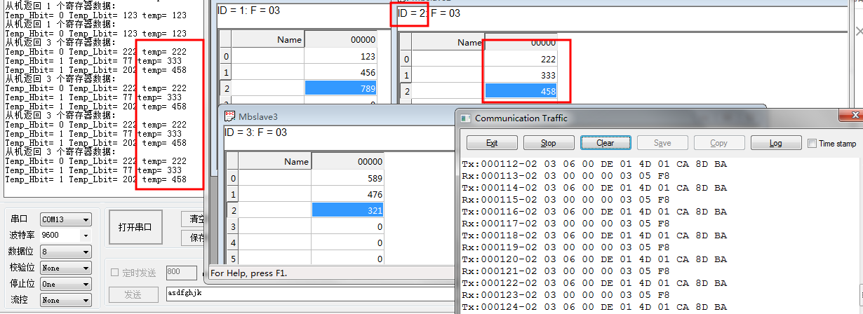
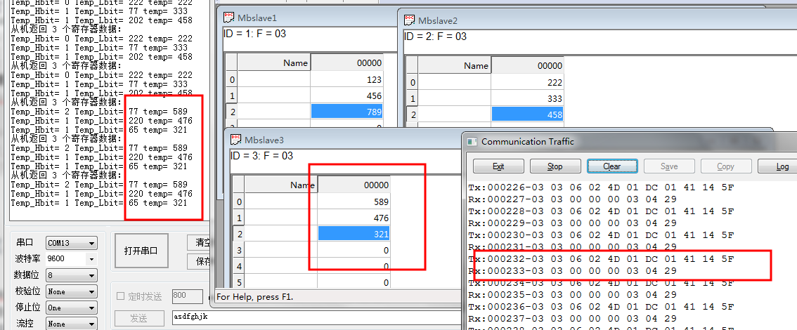
The master part and the slave part are integrated (additional keys and LED (as an aid)
Main functions:
(1)No key pressed:
When no key is pressed, it is the host mode. At this time, the host goes to address the device with slave address 01 to obtain data
(2)When a key is pressed:
Addressing different slaves through keys
 Press key 1 to view the data of slave 01
 Press key 2 to view the data of slave 02
 Press key 3 to view the data of slave 03
 Press key 4 to switch from the master to the slave mode (this device is used as the slave address 0) x02)
-
Variable definition:
 //The added key switches the master mode to the slave mode
 int slave=0;//Slave id
 int host_slave_flag=0;//0 - the device is the master by default, 1 - the device switches to the slave mode
 uint8_t key_value=0;//Which key pressed 1-4
 uint8_t key_flag=0;//key_flag equal to 0 means that the key has never been pressed (at this time, the data of slave 1 is always checked) -- if this flag is not added, reset operation is required after downloading the program
-
Key part
//Press key 1 to view the data of slave 01
//Press key 2 to view the data of slave 02
//Press key 3 to view the data of slave 03
//Press key 4 to switch from the host to the slave mode (this device is used as the slave address 0x02)void key_Send() { key_value=KEY_Scan(1); switch(key_value) { case 1: slave=1;key_flag=1;break;//Slave address 01 case 2: slave=2;key_flag=1;break;//Slave address 02 case 3: slave=3;key_flag=1;break;//Slave address 03 case 4: host_slave_flag=1;key_flag=1;break;//Switch to slave mode } } -
Main function part
int main(void) { delay_init(); //Delay function initialization NVIC_Configuration(); //Set NVIC interrupt packet 2: 2-bit preemption priority and 2-bit response priority uart_init(9600); //Serial port 1 is initialized to 9600 (only used to print test data) LED_Init(); //LED port initialization KEY_Init(); //Initialize the hardware interface connected with the key Modbus_uart2_init(4800);//Initialize modbus serial port 2 and 485 control pins Modbus_TIME3_Init(7200-1,10-1);//Timer initialization parameter 1 is the number of reloads, and parameter 2 is the frequency division coefficient / / 1ms interrupt once Modbus_Init();//MODBUS initialization -- the local machine is used as the slave device address, and the slave address to be matched by the local machine while(1) { key_Send();//Key scan if(host_slave_flag==1)//This is when the key 4 is pressed, indicating that it is in slave mode (led4 keeps flashing) { Modbus_Event();//Modbus event handling function (execute read or write judgment) -- slave address 01 if(Reg[3]==0x0A)//As a slave, if the address 00 03 of the register receives 0x0A data, open LED3 { LED1=0; } if(Reg[3]==0x0B) { LED1=1; } LED4=~LED4; delay_ms(100); } else if(key_flag==0)//Indicates that no key is pressed after power on (master mode to view the data of slave address 01) { //Parameter 1: view the i-th slave data Host_Read03_slave(0x01,0x0000,0x0001);//Parameter 2 start address, parameter 3 number of registers if(modbus.Host_send_flag) { modbus.Host_Sendtime=0;//After sending, the count is cleared (time from last time) modbus.Host_time_flag=0;//Send data flag bit reset modbus.Host_send_flag=0;//Clear the end of transmission data flag bit HOST_ModbusRX();//Receive data for processing } LED2=~LED2; delay_ms(1000); } else { if(modbus.Host_time_flag)//Send data every 1s { //Parameter 1: view the i-th slave data Host_Read03_slave(slave,0x0000,0x0003);//, starting address of parameter 2, number of registers of parameter 3 if(modbus.Host_send_flag) { modbus.Host_Sendtime=0;//After sending, the count is cleared (time from last time) modbus.Host_time_flag=0;//Send data flag bit reset modbus.Host_send_flag=0;//Clear the end of transmission data flag bit HOST_ModbusRX();//Receive data for processing } LED3=~LED3; } } } } -
Test:
-
Press key 4 and use modbus poll as the host link, as shown in the figure
Read operation:
Write operation
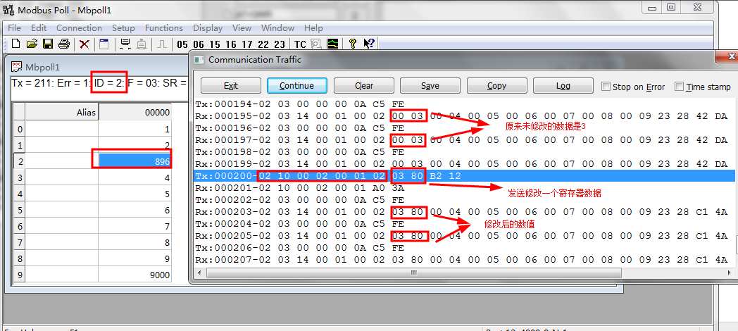
Write multiple registers
-
Download on behalf of mom
Mode 1 code download link - STM32+RS485+MODBUS Protocol (host + slave code) + serial port + timer
(2) Data transfer mode using DMA
Transfer using DMA data
Reference link for the use of DMA: it is very helpful for the use of DMA
STM32-DMA data transfer (USART-ADC-array) – link 1
STM32-ADC (independent mode, dual mode) + DMA read data + some basic knowledge – link 2
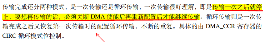
There are two kinds of DMA data transmission: conventional mode and cyclic mode. The conventional mode is used here. Since the data can only be sent once in the conventional mode, it is certainly not allowed to send the data only once, because we have to send the data many times, so we should first solve this problem and realize that the data can be sent many times.
Before using it, you must first carry out DMA transmission data transformation on the basis of serial port transmission data, and finally realize multiple transmission of data. For specific understanding, refer to the blogger's blog below for learning, and then go to the code directly below.
STM32 DMA normal mode waits for the transfer to complete and start the next transfer - link
-
Re enable DMA
This function needs to be called to re enable before DMA sends data every time
When the master addresses the slave, the number of bytes sent is always 8 bytes of data//This is the number of DMA reload transfers and enabled void DMA_TX_Enable() { //Reload and enable the number of characters to be sent DMA_Cmd (DMA1_Channel7,DISABLE);//Close DMA channel DMA_ClearFlag(DMA1_FLAG_TC7);//Clear sign DMA_SetCurrDataCounter(DMA1_Channel7,8);//Reset number of transfers DMA_Cmd (DMA1_Channel7,ENABLE);//Open DMA channel }Since sending data needs to be re enabled, we also need to re enable receiving data. It is impossible to receive data only once. When the host addresses the slave, the number of data bytes returned by the slave = fixed 5 bytes + number of registers * 2
//This is the number of dmA reload transfers and enable (dmA receive) void DMA_RX_Enable(uint8_t num)//Number of num registers { DMA_Cmd(DMA1_Channel6,DISABLE); DMA_ClearFlag(DMA1_FLAG_TC6);//Clear this receive flag bit first DMA_SetCurrDataCounter(DMA1_Channel6, num*2+5); //This is the number of characters returned from the machine: read_num*2+5 DMA_Cmd(DMA1_Channel6, ENABLE); } -
DMA transmit data function
//DMA transmit data function void DMA_TX_data() { //send data RS485_TX_ENABLE;//Enable 485 control terminal (start sending) while(DMA_GetFlagStatus(DMA1_FLAG_TC7)==RESET);//If the return value bit reset indicates that the transmission has not succeeded yet. / / wait until the transmission is completed delay_ms(5);//If this delay is not added, the last two bytes of data will be lost RS485_RX_ENABLE;//Turn on reception } -
The host fills in the data sent + processes the data returned from the slave
//The addressing slave sends instructions and processes the received data //Parameter 1 slave address, parameter 2 start address, parameter 3 number of registers void read03(uint8_t slave,uint16_t StartAddr,uint16_t num) { //send data Host_read03_set(slave,StartAddr,num); //Received data processing if(modbus.Host_End!=1) { HOST_ModbusRX();//Data processing } } -
Function integration
The above function calls are integrated and used. Calling this function in the main function can realize the processing of data sending and receiving
//Read the register data parameter setting of the slave and send data void Host_read03_set(uint8_t slave,uint16_t StartAddr,uint16_t num) { //Send re enable DMA_TX_Enable();//Send re enable Host_Read03_slave(slave,StartAddr,num);//Fill the array contents of the sent data modbus.Host_End=0;//The data processing completion flag bit is cleared DMA_TX_data();//send data //Receive re enable DMA_RX_Enable(num);//Number of received data reloaded -- number of num registers } -
The master writes a data function to a register of the slave
//Parameter setting + data sending void Host_write06_set(uint8_t slave,uint8_t fun,uint16_t StartAddr,uint16_t num) { //Send re enable DMA_TX_Enable();//Send re enable Host_write06_slave(slave,fun,StartAddr,num); modbus.Host_End=0; //send data DMA_TX_data(); //Receive re enable DMA_RX_Enable(num);//Number of received data reloaded -- number of num registers } -
DMA interrupt function
(only enable the DMA receive interrupt. Except for the basic initialization configuration, serial port 2 does not need to enable the interrupt and does not need to write the interrupt service function)
//DMA receive interrupt void DMA1_Channel6_IRQHandler() { //This is the end of data reading DMA_ClearITPendingBit(DMA1_IT_TC6);//Clear transmission completion flag bit modbus.reflag=1;//Indicates that the data is received } -
main.c. contents of documents
The functions and usage are described as follows:
/*
Serial port 1 print data 9600
 Serial port 2 is 485Modbus communication 4800
 It mainly realizes the use of function codes 0x03 and 0x06 when acting as a host

Function 1 reads the register data of the slave
//Parameter 1 slave address, parameter 2 start address, parameter 3 number of registers
void read03(uint8_t slave,uint16_t StartAddr,uint16_t num);

Function 2: write data to a register of the slave
 Parameter address of parameter 1, parameter address of parameter 2, write function code of slave 3
void Host_write06_set(uint8_t slave,uint8_t fun,uint16_t StartAddr,uint16_t num)

The code test part of function code 0x03 is defaulted in the main cycle

What is commented out below is that 0x06 writes a register data

*/
-
Macro definition settings
//Macro definition setting area
#define sl_ID 0x01 / / slave address
#define st_address 0x0000 / / starting address
#define sl_num 3 / / read the number of registers
#define slave_count 3 / / the number of slaves to read -
Main function content
int main(void) { int i=sl_ID ; //First slave address delay_init(); //Delay function initialization NVIC_Configuration(); //Set NVIC interrupt packet 2: 2-bit preemption priority and 2-bit response priority uart_init(9600); //Serial port 1 is initialized to 9600 (only used to print test data) LED_Init(); //LED port initialization KEY_Init(); //Initialize the hardware interface connected with the key USART2_DMA_TX_config();//DMA send initialization USART2_DMA_RX_config();//DMA receive initialization Modbus_uart2_init(4800);//Initialize modbus serial port 2 and 485 control pins Modbus_TIME3_Init(7200-1,10-1);//Timer initialization parameter 1 is the number of reloads, and parameter 2 is the frequency division coefficient / / 1ms interrupt once Modbus_Init();//MODBUS initialization -- the local machine is used as the slave device address, and the slave address to be matched by the local machine USART_DMACmd(USART2,USART_DMAReq_Tx,ENABLE);//Enable on USART_DMACmd(USART2,USART_DMAReq_Rx,ENABLE);//Enable on modbus.Host_End=1; while(1) { if(modbus.Host_time_flag)//1s time to flag bit { modbus.Host_time_flag=0; modbus.Host_Sendtime=0;//The timing flag bit is cleared //Slave address, starting address, number of registers read03(i,st_address,sl_num);//data processing if(modbus.Host_End)//Flag bit after data processing { i++;//Slave address + 1 if(i>slave_count)//Judging from the number of slave machines i=1;//First slave address } } Write data to the register test section, you can open the comment test to write data //send data // Host_write06_set(0x01,0x06,0x0003,0x0089);// Write 0x0089 (decimal 137) to the register address 0x0003 of slave 01 // //Received data processing // if(modbus.Host_End!=1) // { // Host_Func6();// Data processing // } // delay_ms(1000); // LED0=~LED0; } } -
Test:

-
Code download
6, Using HAL library for development
-
Initial HAL Library
This HAL library is an accident, maybe a new beginning. The teacher thought I had been learning how to use HAL library. In fact, I had been reading STM32 standard library, so that after I sent the written code to the teacher, the next day the teacher asked me how to configure it, and I knew that we were poor, Then use one day to change the code into HAL Library Based on the standard library (directly copy the modbus folder under the standard library, make some modifications in the past, and only use stm32cube for timer, serial port and RS485 configuration)
I began to plan to directly use HAL library to transfer data in the form of DMA. After many times of unsuccessful changes, I gave up. I directly sent and received data in the form of overtime reception through the serial port. After experiencing DMA, this recognition is relatively fast, and I'm sure I can't do it directly through the serial port. Of course, I should start from lighting up. First, learn to use STM32cube to generate code to light up the light and do key experiments, Then I felt a little before I started to make some big moves. Serial port 1, serial port 2, timer and RS485 control pins went into battle together.
Because the first use of HAL library has really stepped on a lot of thunder, there is still a lot of gap with the development of standard library. HAL library is the mainstream. Maybe it's time to learn from HAL library.
(1) STM32cube software configuration
-
In the process of use, mainly refer to the following blogs
1-STM32CubeMX tutorial - function introduction
2-STM32 serial port receiving interrupt -- Based on HAL Library
-
Main parts used
In the process of generating code, the enabling pin of RS485 sending / receiving data, serial port 1 (for printing debugging information), serial port 2 (for 485 communication) and timer 1 are mainly used for timing counting
-
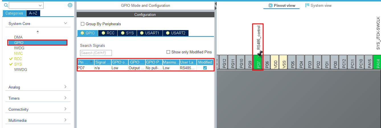
485 enable pin
The 485 enable pin is PD7, which can be set to the output mode. It is also named RS485_contrl
-
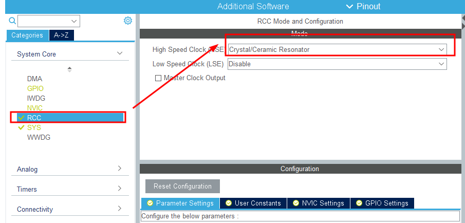
RCC setting
-
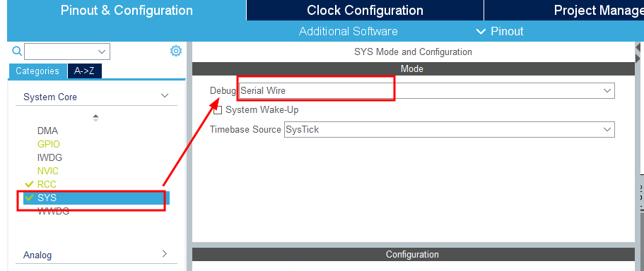
sys settings are as follows:
I seriously doubt that it was because I forgot to choose here that the simulator could not be used
-
Serial port 1
-
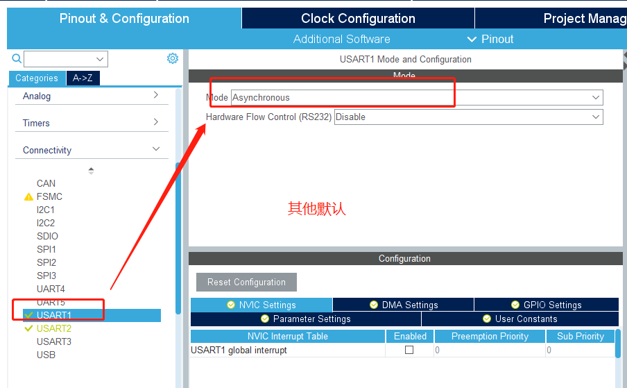
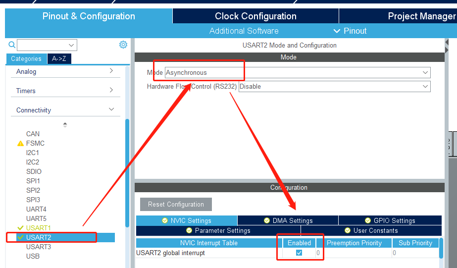
Serial port 2
The serial port 2 is interrupted to enable (it needs to be used when receiving data), and other settings are set by default
-
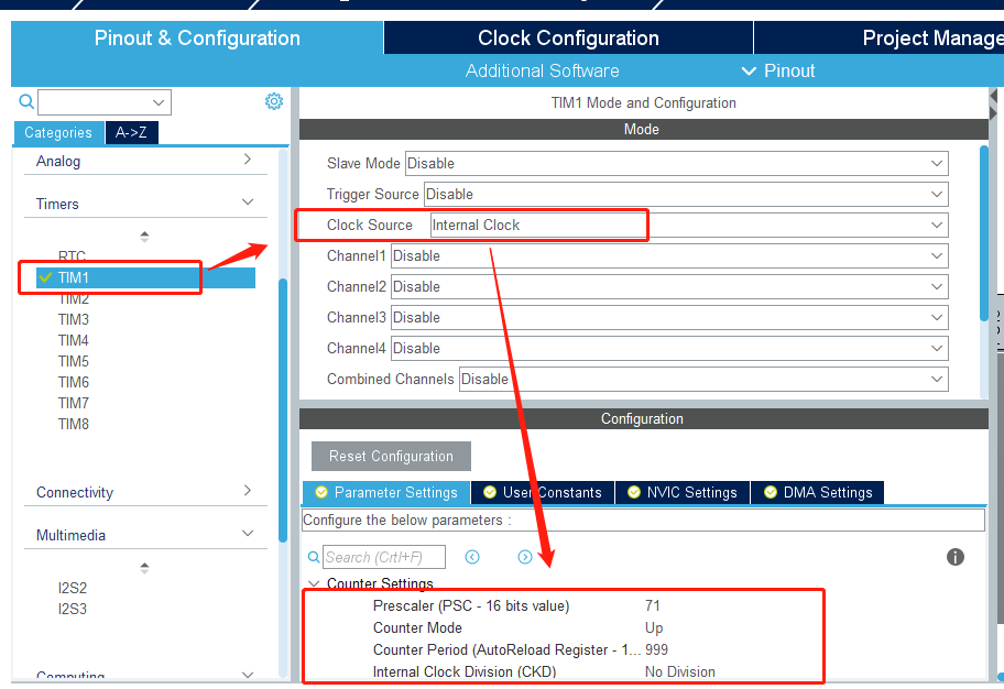
timer
Configure timer 1, timing 1ms configuration (other settings default)
The process of timer 1 configuration using software can be fully referred to this blog
-
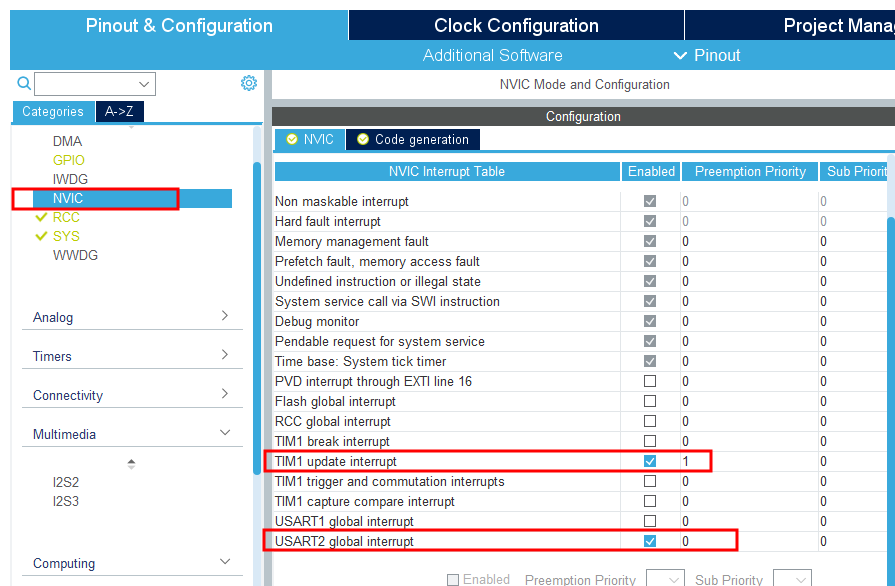
NVIC part
-
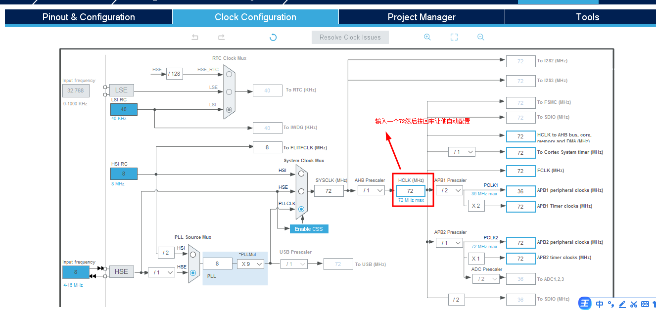
Clock configuration:
According to the specified position in the figure, enter 72 for automatic configuration,
-
Generate code
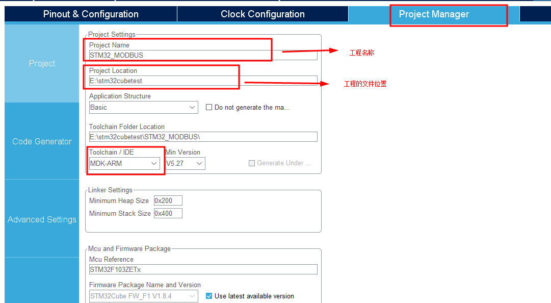
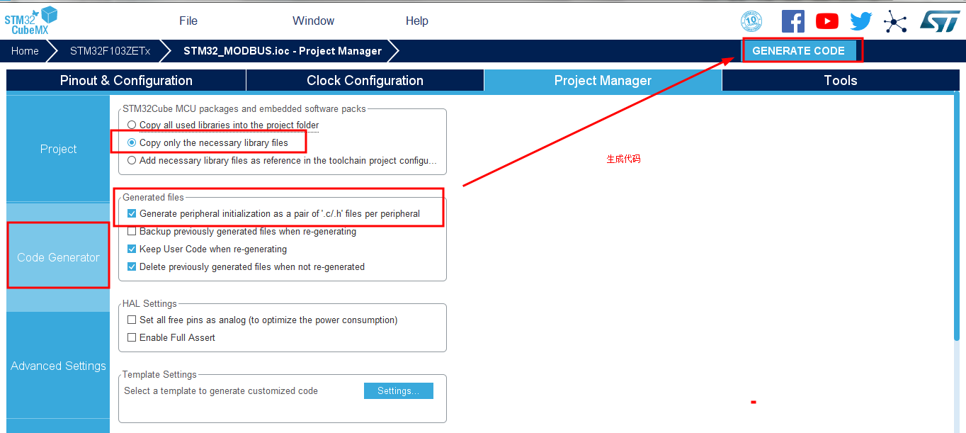
In this way, the configuration of the software can be completed in a few simple steps. We can generate part of the code we need, and then modify it based on the generated code
(2) Code editing
-
Serial port 1 redirection
First, the serial port 1 part of the code transformation - redirect printf
FILE undefined problem in STM32 serial port redirection printf - refer to link 1
STM32 printf panic printf half host mode – refer to link 2
At UART Add the following code to the C file so that you can print debugging information directly with printf ----- don't forget to call stdio H header file/* USER CODE BEGIN 0 */ //Serial port 1 redirection #if 1 #pragma import(__use_no_semihosting) //Support functions required by the standard library struct __FILE { int handle; }; FILE __stdout; //Definition_ sys_exit() to avoid using half host mode void _sys_exit(int x) { x = x; } //Redefine fputc function int fputc(int ch, FILE *f) { /* Place your implementation of fputc here */ /* e.g. write a character to the EVAL_COM1 and Loop until the end of transmission */ HAL_UART_Transmit(&huart1, (uint8_t *)&ch, 1, 0xfff); return ch; } #endif /* USER CODE END 0 */ -
Add the following code to the serial port 2 interrupt service function
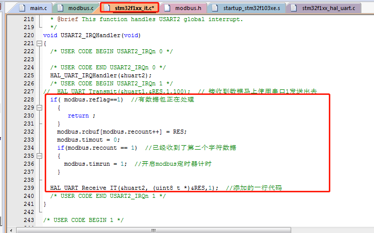
/* USER CODE BEGIN USART2_IRQn 1 */ // HAL_ UART_ Transmit(&huart1,&RES,1,100); // After receiving the data, use serial port 1 to send it out immediately if( modbus.reflag==1) //A packet is being processed { return ; } modbus.rcbuf[modbus.recount++] = RES; modbus.timout = 0; if(modbus.recount == 1) //The second character data has been received { modbus.timrun = 1; //Start modbus timer timing } HAL_UART_Receive_IT(&huart2, (uint8_t *)&RES,1); //Add a line of code /* USER CODE END USART2_IRQn 1 */ -
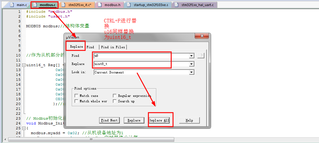
MODBUS file
modbus.c file and MODBUS H file can be directly copied and added, and the corresponding header file can be called where the header file is called
Also replace it
Replace u16 with uint16_t
Replace with uint u8_ t
-
In main Add the following code to H
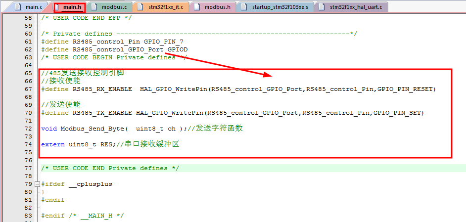
 /* USER CODE BEGIN Private defines */

 //485 transmit receive control pin
 //Receive enable
 #define RS485_RX_ENABLE  HAL_GPIO_WritePin(RS485_control_GPIO_Port,RS485_control_Pin,GPIO_PIN_RESET)

 //Send enable
 #define RS485_TX_ENABLE HAL_GPIO_WritePin(RS485_control_GPIO_Port,RS485_control_Pin,GPIO_PIN_SET)

 void Modbus_Send_Byte(  uint8_t ch );//Send character function

 extern uint8_t RES;//Serial port receiving buffer


 /* USER CODE END Private defines */
-
In main Add the following code to C
Add a function to send data using serial port 2 (485 communication)
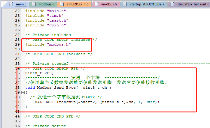
/* USER CODE BEGIN PTD */ uint8_t RES; /***************** Send a character**********************/ //Enable the sending pin before sending single byte data, and enable the receiving pin after sending. void Modbus_Send_Byte( uint8_t ch ) { /* Send a byte of data to USART2 */ HAL_UART_Transmit(&huart2, (uint8_t *)&ch, 1, 0xff); } /* USER CODE END PTD */ -
Add the code of timer part below the main function
/* USER CODE BEGIN 4 */ void HAL_TIM_PeriodElapsedCallback(TIM_HandleTypeDef *htim){ if (htim->Instance == htim1.Instance) { if(modbus.timrun != 0)//Run time= 0 indicates { modbus.timout++; if(modbus.timout >=8) { modbus.timrun = 0; modbus.reflag = 1;//Finished receiving data } } modbus.Host_Sendtime++;//Time count after sending the last frame if(modbus.Host_Sendtime>1000)//It's 1s from sending the last frame of data { //1s time modbus.Host_time_flag=1;//Send data flag position 1 } } } /* USER CODE END 4 */ -
Add the following code to the initialization part of the main function
/* USER CODE BEGIN 2 */ Modbus_Init();//Initialization when this machine is used as a slave HAL_TIM_Base_Start_IT(&htim1); printf("RS485_TEST_01\r\n"); RS485_RX_ENABLE; HAL_UART_Receive_IT(&huart2, (uint8_t *)&RES, 1);//Call receive interrupt function /* USER CODE END 2 */ -
while(1) main code
It includes 3 parts of tests (each part needs to be tested separately)
1 - host reading slave data test (note has been opened)
2 - the master writes data to a register of the slave
3 - the device is used as a slave. When it is used as a slave, the address is 0x02. After testing, comment out one and then open another test/* USER CODE BEGIN WHILE */ while (1) { if(modbus.Host_time_flag)//Send data every 1s { //01 read slave data test //Parameter 1: view the i-th slave data Host_Read03_slave(0x01,0x0000,0x0003);//Parameter 1 slave address, parameter 2 start address, parameter 3 number of registers if(modbus.Host_send_flag) { modbus.Host_Sendtime=0;//After sending, the count is cleared (time from last time) modbus.Host_time_flag=0;//Send data flag bit reset modbus.Host_send_flag=0;//Clear the end of transmission data flag bit HOST_ModbusRX();//Receive data for processing } // //02 write data test // Host_write06_slave(0x01,0x06,0x0001,0x0045); // if(modbus.Host_send_flag) // { // modbus.Host_Sendtime=0;// After sending, the count is cleared (time from last time) // modbus.Host_time_flag=0;// Send data flag bit reset // modbus.Host_send_flag=0;// Clear the end of transmission data flag bit // Host_Func6();// Slave return data processing // } // // // //3 - used as a slave // Modbus_Event();// When this machine is used as a slave } // HAL_Delay(1000); /* USER CODE END WHILE */ /* USER CODE BEGIN 3 */ }STM32 standard library and HAL library have been introduced.
-
Code download
(3) HAL library stepped on the thunder
Finally, let's talk about the thunder stepped by HAL Library:
-
1 - the code is not placed in the specified position and is lost
At the beginning, I didn't know that the code I wrote must be written to the specified area. If it's not the location of the user area, the code written before will be written in vain when the code is regenerated and loaded, and the real code will disappear completely The code was lost twice before the problem was found
-
2 - the emulator fails and the board cannot be downloaded
The emulator used is a driver free type. After downloading a program, it does prompt that the emulator cannot be detected and the program cannot be downloaded. Changing the board is still the same situation. - I tried many methods on Baidu, but I had to change the download mode (I didn't dare to try)
It really wastes a lot of time here. I have to admit it. The emulator can't work. There are serial port downloads. Then I use the serial port download program. When I find it can, I try to download the emulator. It can actually be used - and then I found the correct solution.Reference link 1
Reference link 2
Avoid this error: remember to choose the debug method
The most direct way to solve the problem: use the serial port download program to solve this problem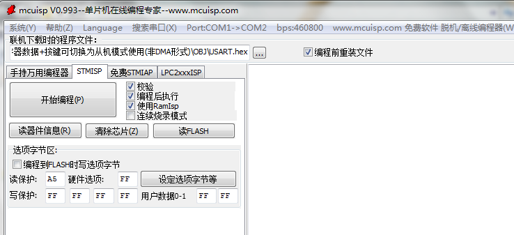
-
3. Code error generated using STM32cube
-
4. File save failed - what a big problem
The regenerated code needs to be loaded. In most cases, click "yes" to update the code, and there are many times that the header file needs to be saved again. When Ctrl+S, you will be prompted with the saved file name and save path. If you save in a new path, even if you add a path, an error will be reported (because there is still a file in the default path), Saving in the default path to replace the file will also cause an error.
-
5. After the end of the year, HAL library development is estimated to continue to step on thunder