1. Overview
USB sound card is nothing more than USB to send PCM data to I2S peripherals or SAI peripherals. After outputting PCM data to DAC through I2S and converting it into analog signal, connect headphones.
Even the expensive Italian digital interface is no exception.
2. Step by step
2.1 USB receiving audio data
2.2 send audio data to DAC
3. Commencement
Two wordy words before commencement:
The author uses STM32F103ZET6\STM32F411CEU\STM32F407VET6\STM32F429IGT6\STM32H743IIT6\STM32H750VBT6 as USB sound card respectively. The USB part of these chips is almost the same in configuration. The biggest difference is that F103\F411\F407 sends audio data to DAC using I2S peripherals. F429\H743\H750 has SAI peripherals, so SAI can be used for sending.
The following detailed introduction takes STM32F411CEU as an example. Because STM32F411CEU has small package and high energy efficiency, it is suitable for occasions with low power consumption, small volume and certain performance. Compared with other chips mentioned above, it is more suitable for digital sound card.
3.1 USB hardware settings
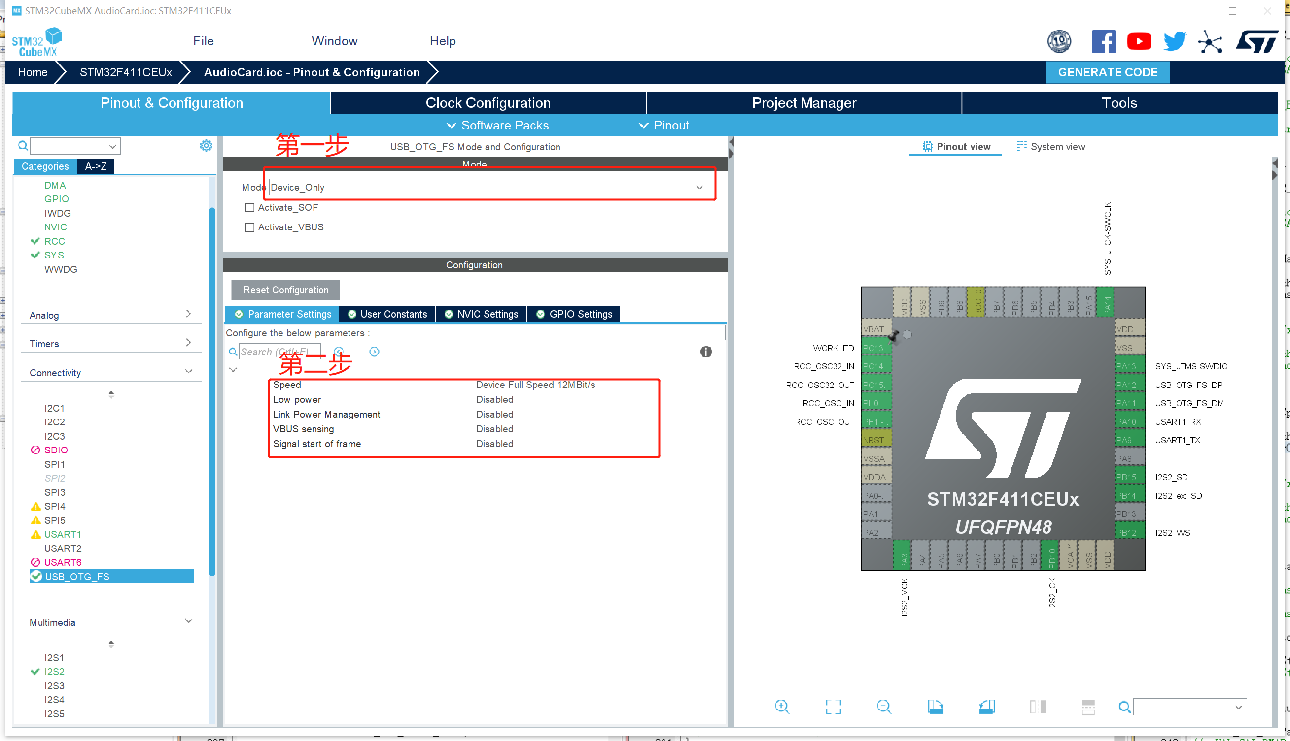
Select device in the first step_ Only, the second step is default
3.2 USB middleware configuration
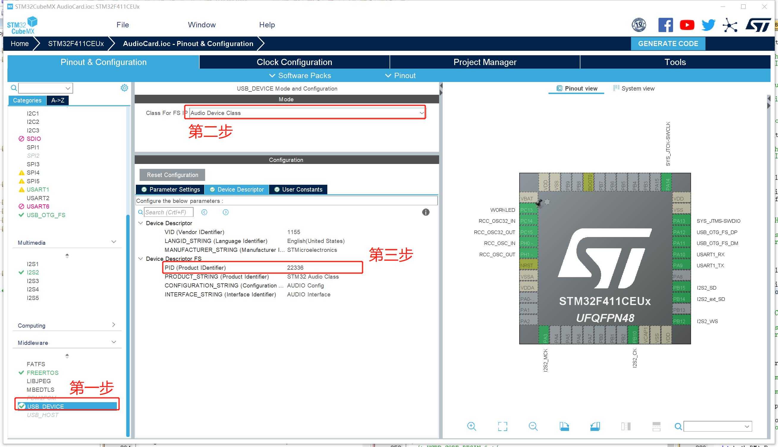
The first step is to find Middleware and select USB_DEVICE, select audio in the second step_ Device_ Class, the third step is to measure this value directly by default, which does not need to be changed.
Now, the USB part is set
3.3 I2S basic setting
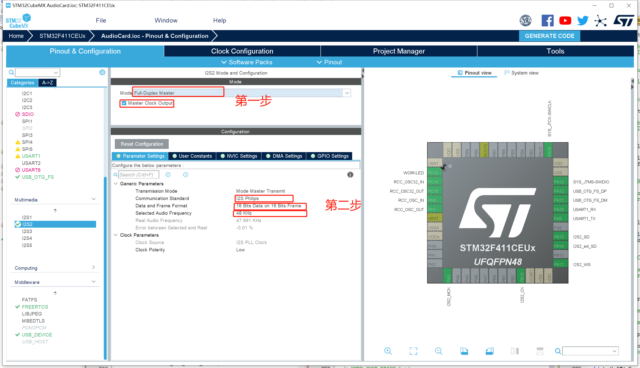
The first step is to set the main mode. Main mode full duplex and half duplex are OK. If you want to realize USB Microphone at the same time and the microphone is sent to the computer through I2S, you need to set it to full duplex mode. Then remember to select Master Clock Output
3.4 DMA settings for audio data transmission
This part is the same when setting whether SAI or I2S is used.
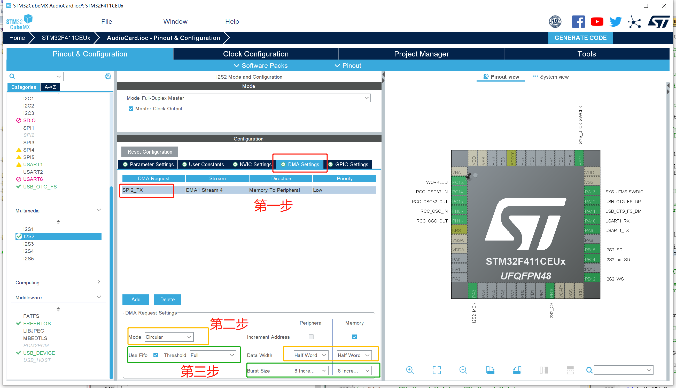
The first step is to select the DMA setting and select the DMA request as send. Only the chip with DMA multiplexer can freely select the DMA data stream. In this example, the chip can only default. Secondly, if the digital sound card is only one of the functions, and multiple functions use DMA, you need to pay attention to the priority of DMA. For those with high real-time requirements, please increase the priority of DMA. In this example, only digital sound card is used, so low priority is selected by default
The second step is to configure the basic parameters of DMA. The DMA mode is set to the cyclic mode and the data bandwidth is set to half word (corresponding to the I2S sending data frame 16bits in the previous section)
The third step is to configure DMA FIFO, which can make DMA requests encapsulated into larger data blocks, so as to reduce the number of memory accesses and make full use of the burst read-write function of SRAM. This part can be set freely. In this example, all FIFOs are used and encapsulated into large data blocks to the greatest extent, and the burst size is set to the maximum. Note: Brut size cannot be changed arbitrarily. Since the depth of FIFO is 4 words, the next 8 data can be loaded in FIFO at most when transmitting half word data, so the maximum burst reading size is 8
3.5 clock configuration
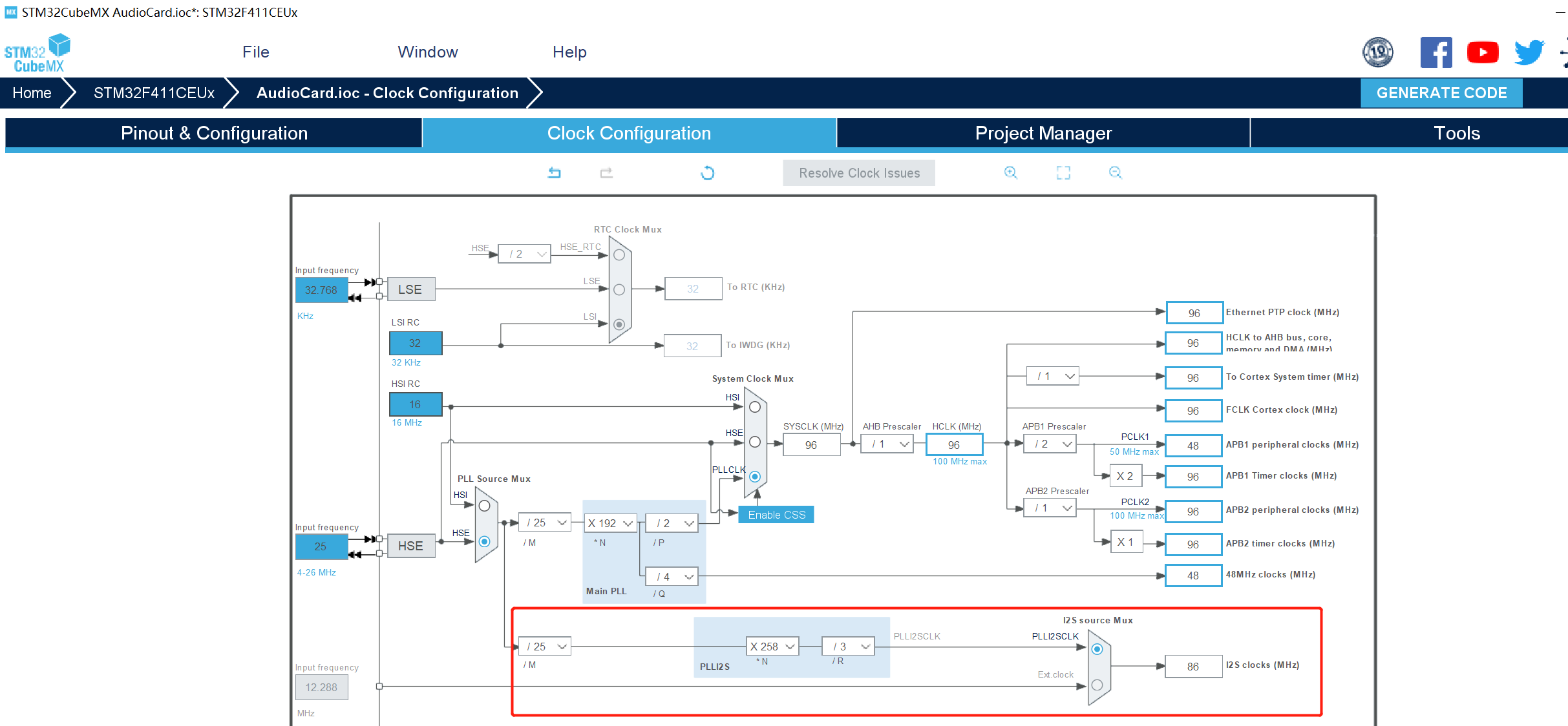
Configure the clock to minimize the error coefficient in the I2S or SAI interface. If fate and I use the same chip and the same sampling rate (48KHZ), you can directly refer to my settings.
3.6 where is the error value?
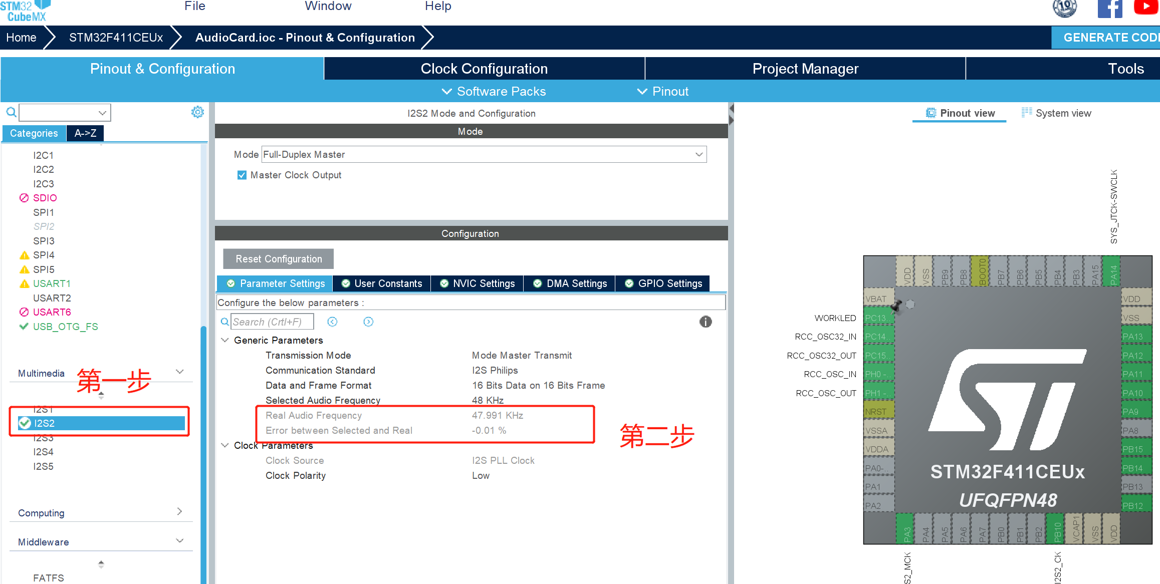
The first step is to select I2S or SAI
Step 2: the current actual frequency and error will be displayed under the selected standard frequency to minimize the Error between Selected and Real. These parameters are directly related to the clock configuration. When adjusting parameters, please switch between the two sides.
3.7 modifying stack size
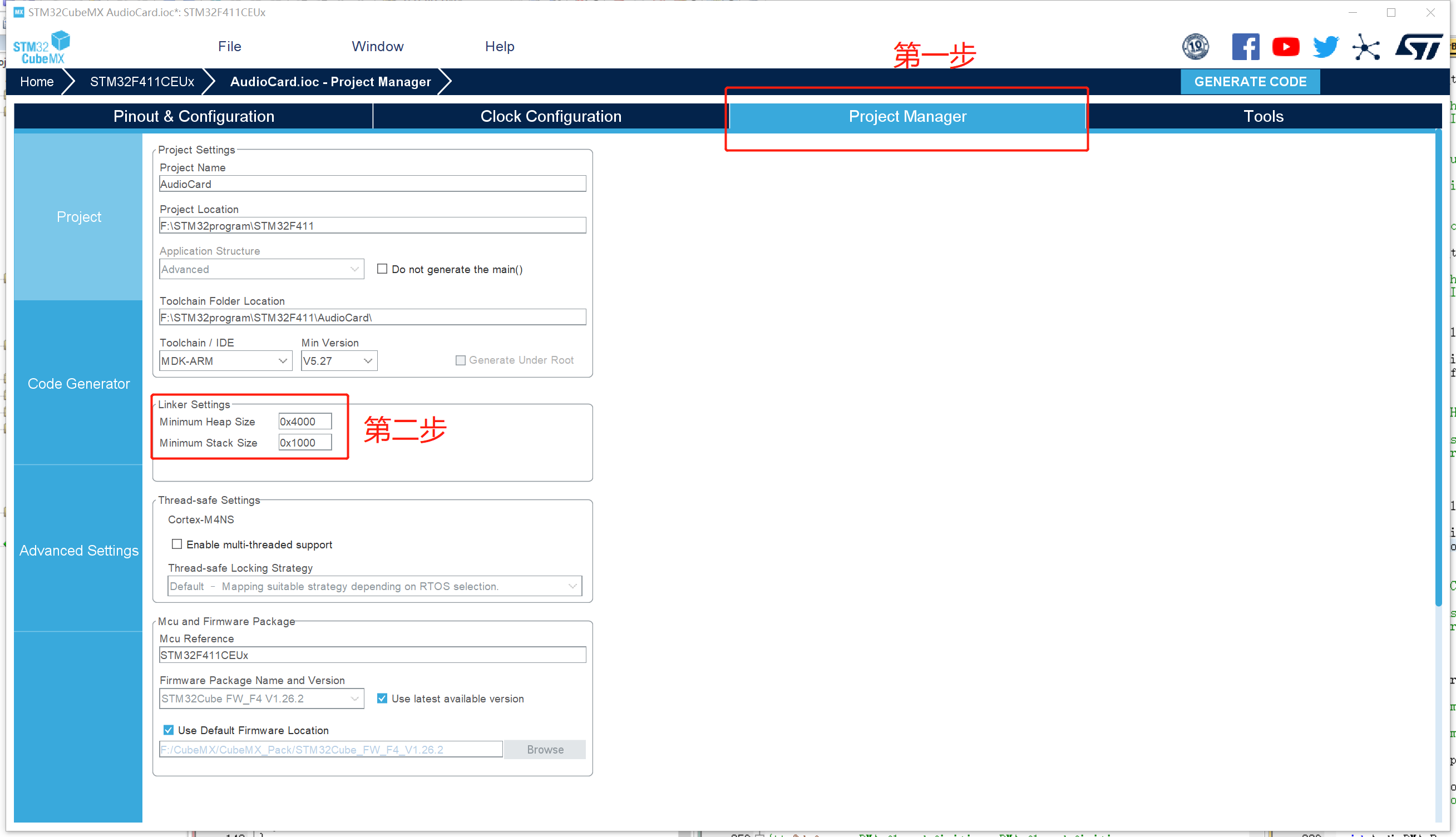
Step 1: select the Project Manager tab
The second step is to modify the stack. Please enlarge it and change it to be the same as me, because the USB function will define many structures with a lot of information. Secondly, the buffer of the digital sound card is also directly applied from the heap by the USB function. So you need to turn up the stack. Of course, if you use the operating system or have your own memory allocation function, you can buffer the memory allocation function at the location defined by the buffer
This function is in usbd_ In conf.c, the source code is as follows
/**
  * @brief  Static single allocation.
  * @param  size: Size of allocated memory
  * @retval None
  */
void *USBD_static_malloc(uint32_t size)
{
  static uint32_t mem[(sizeof(USBD_AUDIO_HandleTypeDef)/4)+1];/* On 32-bit boundary */
  return mem;
}
3.8 change code configuration
USB was originally very complex, and the code part was no exception, but ST officials helped us complete almost all the work. We just need to connect USB and I2S.
The USB part of the whole modification process only needs to fill in usbd_audio_if.c file and the function function encapsulating I2S.
usbd_audio_if.c, the simplest modification is to modify only AUDIO_AudioCmd_FS function and call the synchronization function transfercomplete in the file respectively when I2S is interrupted or semi interrupted_ CallBack_ FS and HalfTransfer_CallBack_FS.
The functions of encapsulating I2S include I2S sending in DMA mode and DMA interrupt processing function. Secondly, it can also encapsulate the suspension, recovery, stop and other functions of DMA for continued use.
void HAL_I2S_TxHalfCpltCallback(I2S_HandleTypeDef *hi2s)
{
	if(hi2s == &hi2s2){
		HalfTransfer_CallBack_FS();//osSemaphoreRelease(SAI3_TX_BUFF0Handle);
	}
}

void HAL_I2S_TxCpltCallback(I2S_HandleTypeDef *hi2s)
{
	if(hi2s == &hi2s2){
		TransferComplete_CallBack_FS();//osSemaphoreRelease(SAI3_TX_BUFF1Handle);
	}
}

AudioPlayerInfo.DMA_TX_NUM);
}
void AudioDMA_Stop(void)//Stop DMA end playback
{
	HAL_I2S_DMAStop(&hi2s2);
}

void AudioDMA_Pause(void)//Pause DMA pause playback
{
	HAL_I2S_DMAPause(&hi2s2);
}

void AudioDMA_Resume(void)//Resume playback from pause
{
	HAL_I2S_DMAResume(&hi2s2);
}

void AudioCard_Play(uint16_t* buff, uint16_t size)//Start playing in sound card mode
{
	HAL_I2S_Transmit_DMA(&hi2s2, buff, size);
}
Modify usbd_ audio_ if. Audio in C_ AudioCmd_ FS function
/**
* @brief Handles AUDIO command.
* @param pbuf: Pointer to buffer of data to be sent
* @param size: Number of data to be sent (in bytes)
* @param cmd: Command opcode
* @retval USBD_OK if all operations are OK else USBD_FAIL
*/
static int8_t AUDIO_AudioCmd_FS(uint8_t* pbuf, uint32_t size, uint8_t cmd)
{
/* USER CODE BEGIN 2 */
switch(cmd)
{
case AUDIO_CMD_START:
AudioCard_Play((uint16_t*)pbuf, size);
break;
case AUDIO_CMD_PLAY:
AudioCard_Play((uint16_t*)pbuf, size);
break;
}
UNUSED(pbuf);
UNUSED(size);
UNUSED(cmd);
return (USBD_OK);
/* USER CODE END 2 */
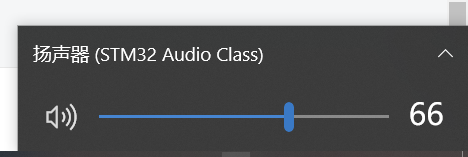
}So far, you can plug it into the computer and select the sound card. After connecting the computer, you can continuously output data from the I2S interface. Connect PCM5120A and plug in headphones to listen to music. Because the PCM5120A is only a DAC, there is no register to be configured. It can be used with simple and rough connection, good sound quality and good power noise suppression. The volume can be adjusted freely in the Windows environment (although the usbd_audio_if.c file indicates that there is no function to adjust the volume). Theoretically, this way of adjusting the volume sacrifices the data accuracy, but in practical use, it has little effect on the sense of hearing.
3.9 add mute function
Business function corresponding to usbd_audio_if.c audio of files_ MuteCtl_ FS (uint8#u t CMD) function. This function will be called when setting mute and contact mute, so you need to add a flag to judge whether it is mute or contact mute. This function can use the pause and resume function of the previously encapsulated I2S function. The modified code is as follows
/**
  * @brief  Controls AUDIO Mute.
  * @param  cmd: command opcode
  * @retval USBD_OK if all operations are OK else USBD_FAIL
  */
static int8_t AUDIO_MuteCtl_FS(uint8_t cmd)
{
  /* USER CODE BEGIN 4 */
  static uint8_t state=0;
  if(state){
	  AudioDMA_Pause();
	  state = 0;
  } else{
	  AudioDMA_Resume();
	  state = 1;
  }
  UNUSED(cmd);
  return (USBD_OK);
  /* USER CODE END 4 */
}
4 step on the pit
The new version of CUBEMX is very different from the previous version. Many problems have been solved, but sometimes there are some errors in perineum difference and Yang error. In this example, after the above configuration, no sound is found when compiling and burning the code. When debugging, it is found that the I2S transmission completion function will not run at all, that is, I2S does not work continuously. After checking the DMA register, it is found that the control register in the DMA register does not write the initialization value at all. Finally, it was found that during DMA initialization, CUBEMX did not consider initializing DMA when initializing I2S, and put the DMA initialization code behind I2S initialization.
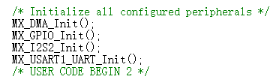
As shown in the figure, the initialization of DMA should be changed to the front of I2S initialization.