Today, the little assistant of positive motion will share with you how the ECI2828 of EtherCAT motion control card uses C# to synchronize PWM output with analog output and motion speed. The application scenarios of this paper include the energy control of laser cutting and laser marking and other applicable scenarios.
I. Introduction to ECI2828 hardware
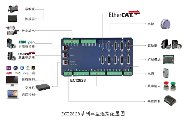
ECI2828 series motion control card supports up to 16 axis linear interpolation, arbitrary arc interpolation, spatial arc interpolation, spiral interpolation, electronic cam, electronic gear, synchronous follow, virtual axis and mechanical finger command; The optimized network communication protocol can realize real-time motion control.
ECI2828 series motion control card supports Ethernet and 232 communication interface to connect with the computer to receive the instructions of the computer. It CAN connect each expansion module through EtherCAT bus and CAN bus, so as to expand the input and output points or motion axis.
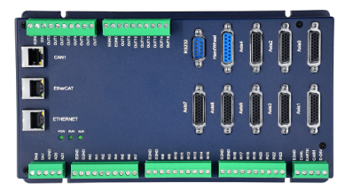
The application program of ECI2828 series motion control card can be developed with VC, VB, VS, C + + and c# software. The dynamic library zmotion is required when the program runs dll. During debugging, ZDevelop software can be connected to the controller at the same time, which is convenient for debugging and observation.
Development of motion control with C# language
Create a new WinForm project and add a function library
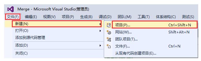
1. In VS2015 menu "file" → "new" → "project", start the create project wizard.
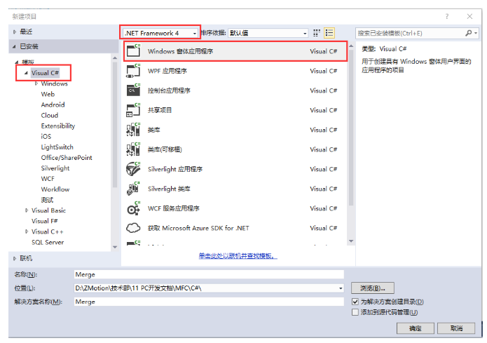
2. Select the development language as "Visual C#" and NET Framework 4 and Windows Forms applications.
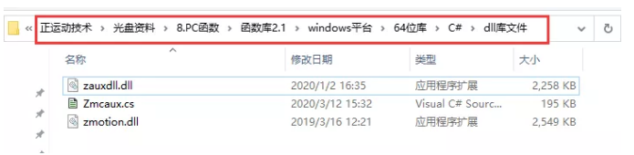
3. Find the C# function library in the CD provided by the manufacturer. The path is as follows (64 bit library as an example):
A. Enter the CD data provided by the manufacturer, find the "8.PC function" folder, and click to enter.

B. Select the "function library 2.1" folder.
C. Select the Windows Platforms folder.
D. Select the corresponding function library as required. Here, select the 64 bit library.
E. Decompress the compressed package of C #, which contains the function library corresponding to C #.
F. The specific path of the function library is as follows.
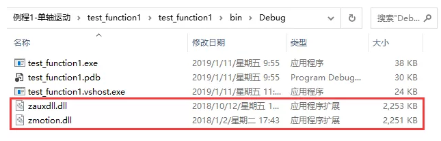
4. Copy the library files and related files of C# provided by the manufacturer to the new project.
A. Zmcaux Copy the CS file to the new project.

B. Zaux DLL and zmotion The DLL file is placed in the bin\debug folder.
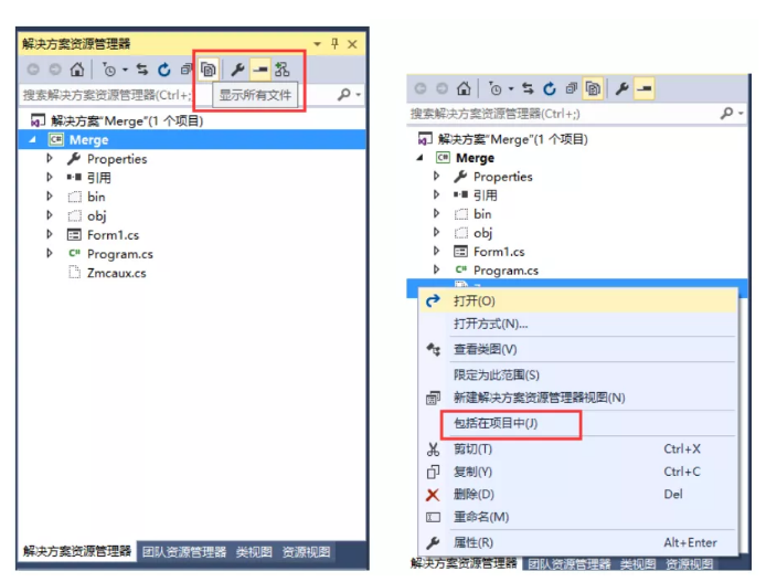
5. Open the new project file with VS, click to display all in the solution explorer on the right, and then right-click zmcaux CS file, click include in project.
6. Double click Form1 In Form1 in CS, the code editing interface appears. Write using cszmcaux at the beginning of the file and declare the controller handle g_handle.

At this point, the new project is completed and the C# project can be developed.
II. Check the PC function manual
1. The PC function manual is also in the CD-ROM. the specific path is as follows: "CD-ROM \ 8.PC function \ function library 2.1\ZMotion function library programming manual V2.1.pdf".

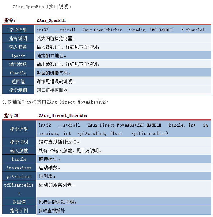
2.PC programming, generally if the network port links the controller and industrial computer. The network interface link function interface is ZAux_OpenEth(); If the link is successful, the interface returns a link handle. By operating this link handle, you can control the controller.

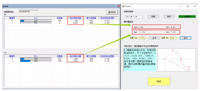
III. realize the synchronization of IO action and motion control
1.C # develops and realizes the interface of IO action and motion control synchronization routine as follows.

2. Application scenario: energy control of laser cutting, energy control of laser marking and other occasions where energy and speed synchronization need to be controlled in the movement process.
3. in the event handler of the link button, the interface function called the link controller is ZAux_. Openeth() is linked with the controller. After the link is successful, start the timer to monitor the IO status of the controller.
  //Link controller

  private void Link_Click(object sender, EventArgs e)

      {

          zmcaux.ZAux_OpenEth(IP_List.Text, out g_handle);

          if (g_handle != (IntPtr)0)

      {

          timer1.Enabled = true;

          //Set link status button

          status.BackColor = System.Drawing.Color.Green;

          status.Text = "Linked";

      }

          else

      {

          MessageBox.Show("Controller Link failed, please check IP address!", "warning");

          //Set link status button

          status.BackColor = System.Drawing.Color.Red;

          status.Text = "Disconnected";

      }

  }
4. Monitor the status information of AD/DA of the controller through the timer.
//Timer 1
private void timer1_Tick(object sender, EventArgs e)
{
  //AD status monitoring

  zmcaux.ZAux_Direct_GetAD(g_handle, 0, ref AIN_Status[0]);

  AIN_Status[0] = AIN_Status[0] / 4096 * 10;

  AD0.Text = "ADO: " + Convert.ToDouble(AIN_Status[0]).ToString("0.00") + "v";

  zmcaux.ZAux_Direct_GetAD(g_handle, 1, ref AIN_Status[1]);

  AIN_Status[1] = AIN_Status[1] / 4096 * 10;

  AD1.Text = "AD1: " + Convert.ToDouble(AIN_Status[1]).ToString("0.00") + "v";

  //DA status monitoring

  zmcaux.ZAux_Direct_GetDA(g_handle, 0, ref AOUT_Status[0]);

  AOUT_Status[0] = AOUT_Status[0] / 4096 * 10;

  DA0.Text = " " + Convert.ToDouble(AOUT_Status[0]).ToString("0.00") + "v";

  zmcaux.ZAux_Direct_GetDA(g_handle, 1, ref AOUT_Status[1]);

  AOUT_Status[1] = AOUT_Status[1] / 4096 * 10;

  DA1.Text = " " + Convert.ToDouble(AOUT_Status[1]).ToString("0.00") + "v";
}
5. Set the analog output through the event processing function of the effective button set by DA.
//Set DA0
private void SetDA0_Click(object sender, EventArgs e)
{
  float DA0_Num = 0;

  DA0_Num = (float)Convert.ToDouble(DA0_data.Text.ToString());

  DA0_Num = DA0_Num / 10 * 4096;

  //Console.WriteLine(DA0_Num);

  zmcaux.ZAux_Direct_SetDA(g_handle, 0, DA0_Num);
}
  //Set DA1

  private void SetDA1_Click(object sender, EventArgs e)
{
  float DA1_Num = 0;

  DA1_Num = (float)Convert.ToDouble(DA1_data.Text.ToString());

  DA1_Num = DA1_Num / 10 * 4096;

  //Console.WriteLine(DA1_Num);

  zmcaux.ZAux_Direct_SetDA(g_handle, 1, DA1_Num);
}
6. Start the test function through the test button, set the forward-looking parameters of the movement, and then control the X and Y axes to carry out continuous interpolation movement to get out of the track of A-B-C-D-E-A.
//Test button
private void TestBotton_Click(object sender, EventArgs e)
{
      int[] AxisList = new int[2];

      float[] DisList = new float[2];

      float[] flag = new float[1];

      flag[0] = 1;

      AxisList[0] = 0;

      AxisList[1] = 1;

      zmcaux.ZAux_Direct_SetTable(g_handle, 0, 1, flag);

      //Axis coordinate reset

      zmcaux.ZAux_Direct_SetDpos(g_handle, 0, 0);

      zmcaux.ZAux_Direct_SetDpos(g_handle, 1, 0);

      //Set the axis parameters (interpolation movement, set the spindle parameters)

      zmcaux.ZAux_Direct_SetSpeed(g_handle, 0, 100); //speed

      zmcaux.ZAux_Direct_SetAccel(g_handle, 0, 2000); //acceleration

      zmcaux.ZAux_Direct_SetDecel(g_handle, 0, 2000); //deceleration

      zmcaux.ZAux_Direct_SetSramp(g_handle, 0, 50); //S curve time

      zmcaux.ZAux_Direct_SetMerge(g_handle, 0, 1); //Turn on continuous interpolation

      //Set motion parameters

      //Corner deceleration

      int mode = 0;

      mode = mode + 2;

      zmcaux.ZAux_Direct_SetCornerMode(g_handle, 0, mode);

      zmcaux.ZAux_Direct_SetDecelAngle(g_handle, 0, (float)(45 * Math.PI / 180));

      zmcaux.ZAux_Direct_SetStopAngle(g_handle, 0, (float)(135 * Math.PI / 180));

      zmcaux.ZAux_Direct_SetForceSpeed(g_handle, 0, 50);

      //Small circle speed limit

      mode = mode + 8;

      zmcaux.ZAux_Direct_SetCornerMode(g_handle, 0, mode);

      zmcaux.ZAux_Direct_SetFullSpRadius(g_handle, 0, 120);

      zmcaux.ZAux_Direct_SetForceSpeed(g_handle, 0, 50);

      //Trigger the oscilloscope on ZDevelop to collect images

      zmcaux.ZAux_Trigger(g_handle);

      //Run to point B

      DisList[0] = 100;

      DisList[1] = 100;

      zmcaux.ZAux_Direct_MoveAbs(g_handle, 2, AxisList, DisList);

      //Run to point C

      zmcaux.ZAux_Direct_MoveCirc2Abs(g_handle, 2, AxisList, 160, 80, 200, 0);

      //Run to point D

      zmcaux.ZAux_Direct_MoveCirc2Abs(g_handle, 2, AxisList, 240, -80, 300, -100);

      //Run to point E

      DisList[0] = 300;

      DisList[1] = -150;

      zmcaux.ZAux_Direct_MoveAbs(g_handle, 2, AxisList, DisList);

      //Run to point A

      DisList[0] = 0;

      DisList[1] = 0;

      zmcaux.ZAux_Direct_MoveAbs(g_handle, 2, AxisList, DisList);

      zmcaux.ZAux_Direct_MoveTable(g_handle, 0, 0, 0);
}
7. Because Windows system is not a real-time operating system, the real-time performance is not high. Therefore, it is necessary to write a Basic program through ZDevelop software to monitor the speed change of interpolation movement in real time, and then update the duty cycle setting and analog output of PWM. The Basic program is as follows:
'eci2820 has three threads. The thread numbers are 0, 1, 2runtask, 1 and lable respectively_ Scan 'start thread 1 and run the real-time scanner
end
lable_scan:dim temp
WHILE 1
ifTABLE(0) and VP_SPEED( 0)<>temp
then
'VP_SPEED indicates the real-time closing speed of axis interpolation motion
AOUT(0) = 10*VP_SPEED(0) 'updates the value of analog output in real time
PWM_ DUTY( 0)=VP_ Speed (0) / 100 'updates the duty cycle of PWM in real time
temp=VP_SPEED(0)
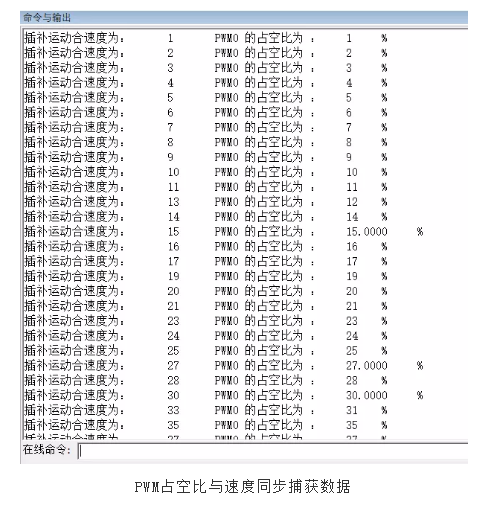
? "Interpolation motion closing speed is:", VP_SPEED(0)
? "Duty cycle of PWM0 is:", PWM_DUTY(0)*100,"%"
endif
WEND
end
IV. commissioning and monitoring
Compile and run the routine, and connect ZDevelop software for debugging to monitor the state of the controller.
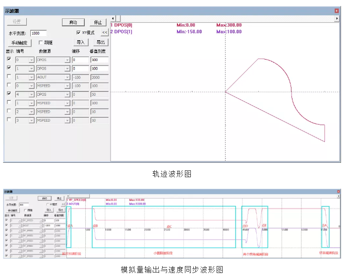
1. Controller status monitoring.
2. Synchronous with PWM output speed and motion.
Simulate the relevant process of laser processing, follow the following path to interpolate from point A(0,0) to point B (100100), walk 1 / 4 circle to point C(200,0) at point B, then walk 1 / 4 circle to point D(300, - 100), finally carry out linear interpolation, pass through point E(300, - 150), and then move to point A(0,0).
Because some forward-looking parameters are set, the speed of motion at different angles is different. However, in order to ensure the same amount of laser at each point, the duty cycle of analog output or PWM should keep step with the speed.
3. Routine demonstration
The PWM of EtherCAT motion control card is synchronized with analog output and motion speed
This time, the synchronization of PWM of EtherCAT motion control card with analog output and motion speed is shared here.
For more interesting content, please pay attention to the official account of the "little sports assistant", and you need the relevant development environment and routine code. Please consult the sales engineer of the sports technology: 400-089-8936.
This article is original by positive motion technology. You are welcome to reprint and learn together to improve China's intelligent manufacturing level. The copyright of this article belongs to rightmovement technology. If you reprint it, please indicate the source of the article.
