IAP15F2K61S2 MCU has two full duplex serial communication interfaces (serial port 1 and serial port 2)
1. Serial port related register

Each serial port has two data buffers, a shift register, a serial controller and a baud rate generator
1.1 data buffer SBUF
These are two physically independent receiving and transmitting buffers, which can send and receive data at the same time.
The transmit buffer is write only and cannot be read, while the receive buffer is read-only and cannot be written. Therefore, the two buffers share one address code
From lines 190 and 192 of STC15F2K60S2 header file, it can be seen that the address of serial port 1SBUF is 99H and the address of serial port 2S2UBF is 9BH.
1.2 serial port (working mode) control register SCON

The serial port of IAP15F2K61S2 MCU has four working modes.
(1) SM0 and SM1 control working mode
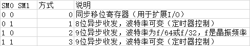
Mode 0: synchronous serial communication
Mode 1: asynchronous serial communication 8 bits, serial port 1 baud rate depends on timer T1, serial port 1 baud rate depends on timer T2, and baud rates are variable
Mode 2: asynchronous serial communication 9 bits (one more parity check bit, or address frame / data frame identification bit). The baud rate depends on the internal crystal oscillator, and the baud rate is not variable
Mode 3: asynchronous serial communication 9 bits (one more parity check bit, or address frame / data frame identification bit), serial port 1 baud rate depends on timer T1, serial port 1 baud rate depends on timer T2, and baud rate is variable
(2) SM2 multi machine communication control bit, used to control whether to activate RI
① When the serial port receives in mode 2 or mode 3:
If SM2 = 1, only when the received 9th bit data (RB8) is "1", set RI to "1", generate an interrupt request, and send the received first 8 bits of data to SBUF. When the received 9th bit data (RB8) is "0", do not set RI to "1", and discard the received first 8 bits of data.
When SM2 = 0, no matter whether the 9th bit data is "1" or "0", the first 8 bits of data are sent to SBUF, and RI is set to "1" to generate an interrupt request.
② For mode 0 and mode 1, SM2 = 0.
(3) TB8 - bit 9 data sent
In multi machine communication, it is used to indicate whether the host sends an address frame or a data frame. TB8=1 is the address frame and TB8=0 is the data frame.
In case of serial communication between two computers, it is parity bit.
(4) RB8 - bit 9 data received
Method 0, RB8 is not used.
In mode 1, RB8 is the received stop bit.
In modes 2 and 3, RB8 stores the received 9th bit data. As address frame / data frame identification bit, or parity bit.
(5) REN - allows serial reception of bits.
Set "1" or clear "0" by software.
REN=1, allowing the serial port to receive data.
REN=0, prohibit the serial port from receiving data.
(6) TI - transmit interrupt flag bit
TI =1, indicating the end of one frame data transmission. TI status can be queried by software or applied for interruption. After the CPU responds to the interrupt, it writes the next frame data to be sent to SBUF in the interrupt service program.
Mode 0: when the 8th bit data sent serially ends, TI is set to "1" by hardware,
In other modes, TI is set to "1" at the beginning of the serial port sending stop bit.
TI must be cleared by software "0"
(7) RI - receive interrupt flag bit
RI=1, indicating that one frame of data has been received, and an interrupt is applied, requiring the CPU to take the data from the receiving SBUF. The status of this bit can also be queried by the software.
In mode 0, when the 8th bit data is received, the RI is set to "1" by the hardware.
In other working modes, when the stop bit is received serially, the position is "1".
RI must be cleared by software "0".
1.3 special function register PCON
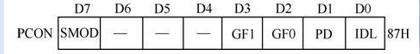
In PCON, only the highest SMOD is related to the serial port: SMOD: baud rate multiplication bit.
When mode 0 (synchronous), this bit is not used, that is, the baud rate speed is not affected by SMOD.
In modes 1, 2 and 3, the baud rate when SMOD=1 is twice as fast as that when SMOD=0. Therefore, SMOD bit is called baud rate multiplication bit.
2. Baud rate
Asynchronous communication is not constrained by the clock line. Both sides of the communication have their own communication frequency (baud rate), and the baud rate of both sides should be the same.
Baud rate setting (fosc:frequency oscillate crystal oscillator frequency)
Baud rate of mode 0 = fosc/12
Baud rate of mode 2 = (2SMOD/64*fosc)
Baud rate of mode 1 = (2SMOD/32) * (T overflow rate)
Baud rate of mode 3 = (2SMOD/32) * (T overflow rate)
Generally, we use the timer as the baud rate generator for serial communication. If two serial ports are used at the same time, we need to prepare two baud rate generators
Serial port 1 uses timer 1 as baud rate generator
Serial port 2 uses timer 2 as baud rate generator
Next, write the function with variable baud rate for serial communication (both serial ports are used)
The 8 bits of S2CON of serial port 2 are not defined in the header file, so they should be defined by themselves
#include <STC15F2K60S2.H>
#include <stdio.h>
#define S2RI  0x01
#define S2TI  0x02
#define S2RB8 0x04
#define S2TB8 0x08
#define S2_S0 0x01
//Define receive array
unsigned char Buffer1[5]={0};//Serial port 1 receiving array
unsigned char Buffer2[5]={0};//Serial port 2 receiving array
unsigned char buf[12]={0}; //Send array
unsigned char i=0,j=0;
void Uart1Init(void)		//9600bps@12.000MHz
{
	SCON = 0x50;		//8-bit data, variable baud rate
	AUXR |= 0x40;		//The clock of timer 1 is Fosc, i.e. 1T
	AUXR &= 0xFE;		//Serial port 1 selects timer 1 as baud rate generator
	TMOD &= 0x0F;		//Set timer 1 to 16 bit automatic reassembly mode
	TL1 = 0xC7;		//Set timing initial value
	TH1 = 0xFE;		//Set timing initial value
	ET1 = 0;		//Disable timer 1 interrupt
	TR1 = 1;		//Start timer 1
	EA=1;
    ES=1;
}
void Uart2Init(void)		//9600bps@12.000MHz
{
	S2CON = 0x50;		//8-bit data, variable baud rate
	AUXR |= 0x04;		//The clock of timer 2 is Fosc, i.e. 1T
	T2L = 0xC7;		//Set timing initial value
	T2H = 0xFE;		//Set timing initial value
	AUXR |= 0x10;		//Start timer 2
}
//Serial port 1 string sending
void Uart_Sendstring(unsigned char *pucStr)
{
 while(*pucStr != '\0')
 {
	 SBUF = *pucStr;
	 while(TI == 0);
	 TI = 0;
	 pucStr++;
 }
}
//Main function
void  main()
{
	Uart1Init();
	Uart2Init();
	sprintf  (buf,"%u","lianglujun");
	while(1)
	{

	}
}

//Interrupt receiving function
void UART1receive() interrupt 4
{
	 if(RI)
	 {
		  Buffer1[i]=SBUF;
		  RI=0;
	 }

	 SBUF=Buffer1[i]; 	//TI =1, indicating the end of one frame data transmission. TI status can be queried by software or applied for interruption
	 while(!TI)	;
	 TI=0;
	 i++;
	 if(i>=5){
	 	i=0;
	 }
}
//Interrupt function
void UART2receive() interrupt 8	using 2
{
    //The receiving flag, S2RI=1, indicates that a frame of data has been received and applies for interruption
	//Because the header file lacks the definition of serial port 2, some bit operations are adopted here
	 if(S2CON &S2RI)
	 {
		  Buffer2[j]=S2BUF;
		  S2CON &= ~S2RI;
	 }

	 S2BUF=Buffer2[j];//send data
	 while(!S2CON & S2TI);
	 S2CON &= ~S2TI;
	 j++;
	 if(j>=5){
	 	j=0;
	 }
}