requirement
1. Planning topology
2. Reasonably configure IP address
3. Plan VLAN information as shown in the figure. PC1/PC2/PC3 belongs to VLAN123 and AR1 belongs to VLAN111
4. MSTP, eth-trunk and VRRP need to be configured reasonably to achieve the best network availability
5. Configure the dynamic routing protocol to make the whole network interconnected, and the private address is not allowed to appear in the ISP
Requirement: AR3 does not allow any routing configuration
6. Configure PC5 as a DHCP server, and all PCs need to automatically obtain the address through DHCP.
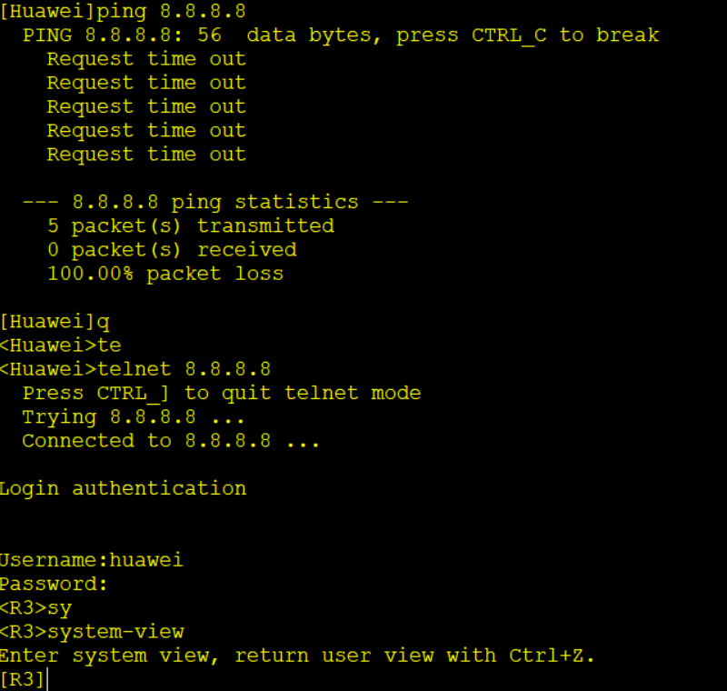
7. Configure the telnet function on AR3 so that AR1 can log in to AR1 for remote management using huawei/123456
8. Only AR1 TELNET to AR3 is allowed, and all other devices cannot TELNET to AR3
The first step is to build a topology map
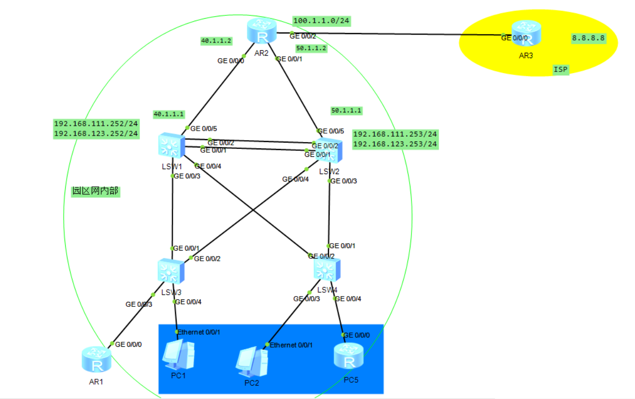
Rational planning of ip address
First configure VLANs 111 and 123, and then divide them into two network segments 10.1.1.0/24 20.1.1.0/24 lsw1. Configure your own ip address. vlan 111 is 20.1.1.252 and VLAN 123 is 10.1.1.252. Lsw2 vlan 111 20.1.1.253 VLAN 123 is 10.1.1.253. The virtual gateways are 10.1.1.254 and 20.1.1.254 respectively.
I didn't demonstrate the interface ip on the router.
Planning vlan 111 123 PC1/PC2/PC3 belongs to VLAN 123 and AR1 belongs to VLAN 111
For lsw1 configuration, configure trunk first, and then aggregate the 1 and 2 interface links. The same is true for lsw2
interface GigabitEthernet0/0/3  # Access interface
 port link-type trunk  # Configure interface mode
 port trunk allow-pass vlan 111 123
interface GigabitEthernet0/0/4
 port link-type trunk
interface GigabitEthernet0/0/5
 port link-type trunk
 to configure ospf You need to divide another one when you need it vlan I use it here vlan 1 To configure 5 ports ip address
 interface Vlanif1
 ip address 40.1.1.2 255.255.255.0
 to configure lacp
 port trunk allow-pass vlan 111 123
 interface Eth-Trunk 1      #Bind the physical interface to eth trunk
 mode lacp-static  # LACP static mode
trunkport GigabitEthernet 0/0/1 0/0/3  # Turn two interfaces into one interface
sw3 configuration, lsw4 similarly, trunk is used for switches and switches, and access port is used for switches and PCs. switches and routers are also trunk
interface GigabitEthernet0/0/1
 port link-type trunk
 port trunk allow-pass vlan 111 123
interface GigabitEthernet0/0/2
 port link-type trunk
 port trunk allow-pass vlan 111 123
interface GigabitEthernet0/0/3
 port link-type access
 port default vlan 111
interface GigabitEthernet0/0/4
 port link-type access
 port default vlan 123
To configure mstp multi spanning tree protocol, first of all, the switch itself defaults to mstp mode, which is required for each switch
stp region-configuration
region-name huawei
revision-level 2021
instance 1 vlan 111
instance 2 vlan 123
active region-configuration  # If you don't type this sentence, the configuration is not written in
quit
stp mode mstp
stp instance 1 root primary  #In the first switch is the primary root
stp instance 2 root secondary # The second switch is standby
stp instance 2 root primary #  The second switch is the master
stp instance 1 root secondary # The first switch is standby
Now you need to configure the vrrp virtual gateway
lsw1
 interface Vlanif111
 ip address 20.1.1.253 255.255.255.0
 vrrp vrid 111 virtual-ip 20.1.1.254  # This is the virtual gateway of vlan 111
 interface Vlanif123
 ip address 10.1.1.253 255.255.255.0
 vrrp vrid 123 virtual-ip 10.1.1.254 # This is the virtual gateway of vlan 123
 lsw2
 interface Vlanif111
 ip address 20.1.1.252 255.255.255.0
 vrrp vrid 111 virtual-ip 20.1.1.254
 interface Vlanif123
 ip address 10.1.1.252 255.255.255.0
 vrrp vrid 123 virtual-ip 10.1.1.254
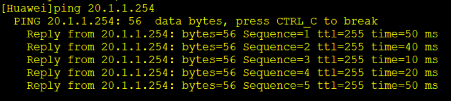
Now you can test the connectivity. It's best to test the connectivity after it is finished, so that you can check the error when there is a problem later.
Now configure ospf dynamic routing protocol
ar2 configuration
ospf 10 router-id 2.2.2.2
 default-route-advertise always
 area 0.0.0.0
  network 40.1.1.0 0.0.0.255
  network 50.1.1.0 0.0.0.255
  withdraw
  ip route-static 0.0.0.0 0.0.0.0 100.1.1.3 Default route
Configuration of lsw1
  ospf 10
 area 0.0.0.0
  network 40.1.1.0 0.0.0.255
  network 10.1.1.0 0.0.0.255
  network 20.1.1.0 0.0.0.255
lsw2 configuration
 ospf 10
 area 0.0.0.0
  network 50.1.1.0 0.0.0.255
  network 20.1.1.0 0.0.0.255
  network 10.1.1.0 0.0.0.255
Configure ar2 nat
ar2 Configuration of
acl number 2000
 rule 5 permit source 20.1.1.0 0.0.0.255
 rule 10 permit source 10.1.1.0 0.0.0.255
 rule 15 permit source 40.1.1.0 0.0.0.255
 rule 20 permit source 50.1.1.0 0.0.0.255
 interface GigabitEthernet0/0/2
 nat outbound 2000
 ip address dhcp-alloc
ar3 configuration
interface LoopBack0  // Configure private address
 ip address 8.8.8.8 255.255.255.255
dhcp configuring pc5 as server
First, call dhcp enable for all devices. / / the dhcp service is started
pc5 configuration
interface GigabitEthernet0/0/0
 ip address 10.1.1.5 255.255.255.0
 dhcp select global

 ip pool isp
 gateway-list 100.1.1.3
 network 100.1.1.0 mask 255.255.255.0
 dns-list 8.8.8.8

ip pool vlan111
 gateway-list 20.1.1.254
 network 20.1.1.0 mask 255.255.255.0
 dns-list 8.8.8.8

 ip pool vlan123
  gateway-list 10.1.1.254
 network 10.1.1.0 mask 255.255.255.0
 excluded-ip-address 10.1.1.252 10.1.1.253
 dns-list 8.8.8.8
 Default route
ip route-static 0.0.0.0 0 10.1.1.254
<Huawei>reset ip pool name vlan103 all //Reset address pool allocation
lsw1 configuration
interface Vlanif111
 dhcp select relay
 dhcp relay server-ip 10.1.1.5  // Meaning of relay
lsw2 configuration
  interface Vlanif111
 dhcp select relay
 dhcp relay server-ip 10.1.1.5
Configuration of r1
interface GigabitEthernet0/0/0
 ip address dhcp-alloc  // The method of obtaining ip address is dhcp
 Default route
 ip route-static 0.0.0.0 0.0.0.0 20.1.1.254
Advanced acl 3000
ar2 configuration
rule 5 deny icmp source 20.1.1.251 0 destination 100.1.1.3 0
 rule 10 deny icmp source 20.1.1.251 0 destination 8.8.8.8 0
 rule 15 deny tcp source 10.1.1.5 0 destination 8.8.8.8 0
 rule 20 deny tcp source 10.1.1.5 0 destination 100.1.1.3 0
You have to disable rules in the interface ar2 1 Port and 2 ports
acl traffic-filter inbound acl 3000
telnet remote login
aaa
local-user huawei password cipher 123456
local-user huawei service-type telnet
local-user huawei privilege level 15
 sign out aaa
user-interface vty 0 4
authentication-mode password
authentication-mode aaa
As required, ar1 cannot ping ar3, but ar3 can be logged in remotely
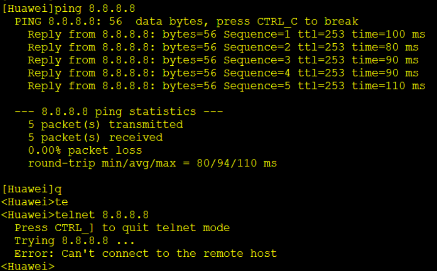
pc5 can ping 8.8.8.8, but not telnet ar3
If there is any error, please point it out. Thank you for browsing!!!