I Hardware scheme
This design is mainly divided into five functions: temperature measurement, humidity and PM2 5 and CO and send information and alarm. With the ingenious combination of these functions with home, we already know how to realize the five separate functions. Now we need to systematically feed back the five functions through single chip microcomputer, so as to achieve a smart home that can integrate the five functions.
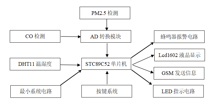
The main hardware involved in the design is: STC89C52RC single chip microcomputer, DHT11 temperature and humidity sensor, GSM module, CO sensor, PM2 5 sensor, key setting, LCD1602 liquid crystal display module, buzzer alarm circuit and over standard indication display module. As shown in the figure:
II Design function
(1) DHT11 temperature and humidity sensor is used to detect temperature and humidity, PM2 5 dust sensor detects air quality, MQ-2 (MQ Series replaceable) smoke sensor detects combustible gas or smoke concentration and sends it to ADC0832 analog-to-digital conversion chip, and 0832 converts analog quantity into digital quantity to single chip microcomputer.
(2) LCD1602 LCD screen is used to display temperature, humidity, smoke concentration and PM2 5 dust data and thresholds of various indicators.
(3) Four keys: key 1 setting, key 2 plus, key 3 minus and key 4 OK. The upper and lower limits of temperature and humidity, the upper limit of smoke and the upper limit of dust can be set by pressing the key. The set value can be stored in the EEPROM inside the single chip microcomputer (STC Series) to realize power down storage, and the set value will not be lost in power down.
(4) When the temperature and humidity value is lower than the lower limit or higher than the upper limit, or the smoke concentration is higher than the upper limit, or the dust data exceeds the upper limit, the corresponding indicator led lights up and the buzzer rings to realize audible and visual alarm.
(5) GSM module is used to send SMS. When any index of each index exceeds the threshold, GSM module will send SMS to mobile phone to remind attention that the sending content is the real-time collected data of each index.
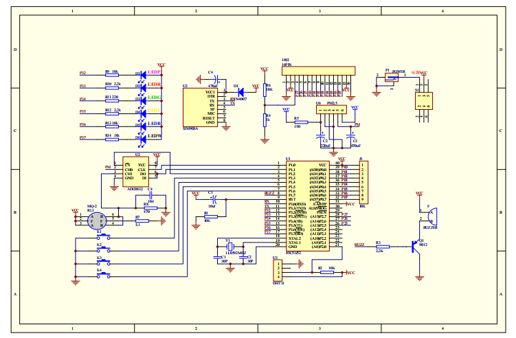
III Design schematic diagram
(1) The schematic diagram is mainly designed by AD software, as shown in the figure:
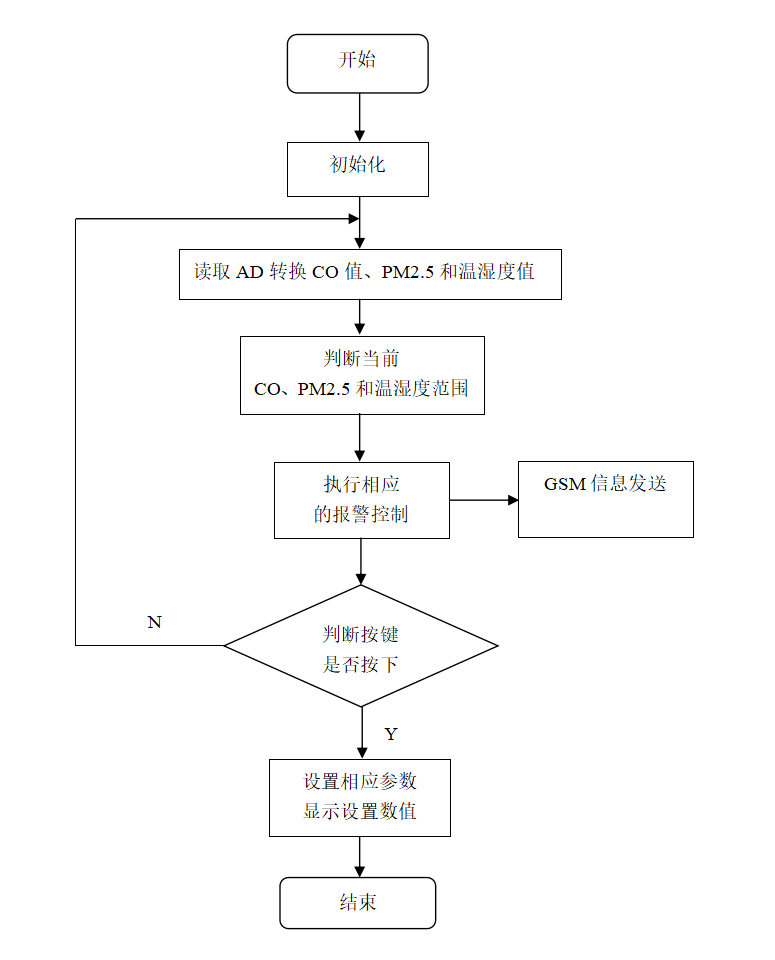
IV software design
(1) Program flow chart
(2) Main program source code
//T:23C P0.12mg/m3
//H:45% C:000mL/m3

/********************************************************************
* Name: Main()
* Function: main function
***********************************************************************/
void main()
{
    uint testnum;
	uchar ys;

    Uart_init();    //Serial port initialization
	RW=0;
  	init_eeprom();  //EEPROM initial drawing
	read_eeprom();    //Read the set value
	L1602_init();     //Initial picture of display screen
	for(ys=0;ys<10;ys++)
	{
		delayms_1000ms();
	}
	SendString("AT\r\n");    //GSM initialization instruction
	delayms_1000ms();
	delayms_1000ms();
	SendString("AT\r\n");
	delayms_1000ms();
	delayms_1000ms();
	SendString("ati\r\n");
	delayms_1000ms();
	delayms_1000ms();
	SendString("ati\r\n");
	delayms_1000ms();
	delayms_1000ms();
	SendString("ATH\r\n");
	delayms_1000ms();
	delayms_1000ms();
	SendString("AT+CMGF=1\r\n");
	delayms_1000ms();
	delayms_1000ms();
	SendString("AT+CNMI=2,1,0,0,0\r\n");
	delayms_1000ms();
	delayms_1000ms();
	SendString("ATH\r\n");
	delayms_1000ms();
	delayms_1000ms();
	SendString("AT+CSCS=");
	SendASC('"');
	SendString("UCS2");
	SendASC('"');
	SendString("\r\n");
	delayms_1000ms();
	write_1602com(0x80);
	write_string("T:  C P .  mg/m3");
	write_1602com(0xc0);
	write_string("H:  % M:   mL/m3");
//	Uart_init();
//	TH=30;TL=20;HH=80;HL=50;COH=100;PMH=100;
	while(1)
	{
		KEY();     //Key scan
		if(flag==0)
		{
			if(FlagStartRH==1)
			{
				testnum = RH();
				FlagStartRH = 0;
	//			TR0 = 1;
				humidity = U8RH_data_H;	 //Read out the temperature and humidity, taking only the integer part
				temperature = U8T_data_H;

				DA=sum/40;
				sum=0;
				PM=DA*(float)(DA/4);
				MQ=adc0832(1);
				display();
			}
			if(temperature>=TH)
			LED1=0;
			else
			LED1=1;
			if(temperature<=TL)
			LED2=0;
			else
			LED2=1;
			if(humidity>=HH)
			LED3=0;
			else
			LED3=1;
			if(humidity<=HL)
			LED4=0;
			else
			LED4=1;
			if(PM/10>=PMH)
			LED5=0;
			else
			LED5=1;
			if(MQ>=MQH)
			LED6=0;
			else
			LED6=1;
			if(temperature>=TH||temperature<=TL||humidity>=HH||humidity<=HL||PM/10>=PMH||MQ>=MQH)    //Judge the current detection value
			{
				Onealarm();
			}
			else
			alarm=1;
			if((temperature>=TH||temperature<=TL||humidity>=HH||humidity<=HL||PM/10>=PMH||MQ>=MQH)&&flag_ok==1)
			{
				TR0=0;
				TransmitText();
				flag_ok=0;
				TR0=1;
			}
		}
	}
}
If you need information, please pay attention to official account design of the single chip microcomputer.