Introduction: Using the mem32 function, for the problem of low PWM frequency accuracy in MM32 micro python, we can improve the PWM frequency accuracy by readjusting the ARR.
Key words: PWM, MM32, micropathon, mem32
§ 01 MM32 PWM output
Advantages and disadvantages of version 1.1
in Micro Python transplantation PWM on MindMotion MM32 single chip microcomputer It is given that SuYong, a smart company, has PWM in the micro Python version transplanted on MM32F3277. Compared with the version given on the official website of micropthon, the PWM advantages of this version are as follows:
- It gives eight channels of PWM output based on two timers (TIM3 and TIM4), so it allows two groups of PWM waveform output with different fundamental frequencies. Thus, the steering gear and DC motor control can be controlled respectively.
but its shortcomings are also obvious in the implementation process. During the implementation of SuYong, for the ARR fixed bit 999, the CNT range of the corresponding PWM is from 0 to 999. It can achieve 1 / 1000 output PWM accuracy. However, the accuracy of the corresponding output PWM frequency is limited.
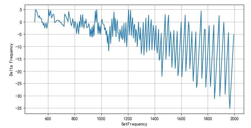
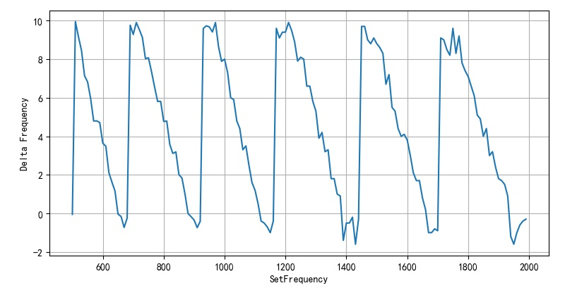
this is Limitations of using mm32 microphoton to generate dual audio signals Measurements were made. The following figure shows the absolute error of MM32 PWM frequency from 500 to 2000Hz.
1.2 error analysis
1.2.1 PWM frequency determination
it is assumed that the Time working frequency of MM32F3277 comes from the main frequency of MCU, corresponding to f o s c = 120 M H z f_{osc} = 120MHz fosc=120MHz . about A R R = 999 ARR = 999 ARR=999, the PWM frequency is determined by the pre distributor PSC of TIM3/TIM4.
f P W M = f o s c ( 1 + P S C ) ⋅ ( A R R + 1 ) f_{PWM} = {{f_{osc} } \over {\left( {1 + PSC} \right) \cdot \left( {ARR + 1} \right)}} fPWM=(1+PSC)⋅(ARR+1)fosc
since PSC must adopt integer, the corresponding output is f P W M f_{PWM} There will be some errors in fPWM.
1.2.2 error
the following is the error between the set frequency and the actual frequency in the range of 500 to 1000.
from headm import *

fset = range(500, 2000, 5)

def deltaf(f):
    fosc = 120e6
    psc = int(fosc/f/1000)-1
    freal = fosc/(1+psc)/1000

    return f-freal

fdel = [deltaf(f) for f in fset]

plt.plot(fset, fdel)

plt.xlabel("Set Frequency(Hz)")
plt.ylabel("Delta Frequency(Hz)")
plt.grid(True)
plt.tight_layout()
plt.show()
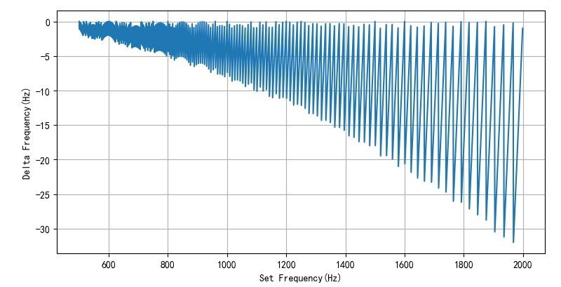
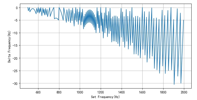
the following is the PWM frequency error calculated every 5Hz, which is different from that in Limitations of using mm32 microphoton to generate dual audio signals The actual measurement results are basically close.
1.3 how to improve PWM frequency error?
this problem mainly comes from the fact that during the realization of SuYong's PWM function, the fixed arr is 999, which makes it impossible to adjust the actual output PWM frequency. A calculation method is given below, so that the ARR can be adjusted according to the error before and after 999, so that the output frequency meets the set frequency.
1.3.1 modification method
the specific modification method is divided into two steps, which are given by the following function:
def deltaf(f):
    fosc = 120e6
    psc = int(fosc/f/1000)-1
    arr = int(fosc/(1+psc)/f) - 1

    freal = fosc/(1+psc)/(1+arr)

    return f-freal,arr
1.3.2 modification results
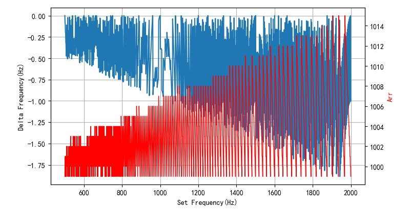
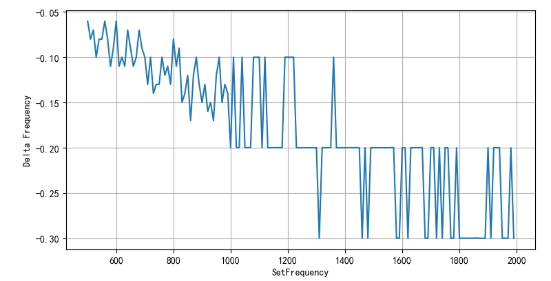
after modification in this way, the corresponding ARR floats around 1000. It can be seen that the corresponding frequency error is less than 1 / 1000
1.4 implementation in micro Python
according to Mm32f3277 micro Python mem function for MCU memory access Description: mem32 technology can be used to directly access the register of MM32F3277, so the PSC and ARR corresponding to the frequency corrected above can be adjusted by mem32. So as to improve the accuracy of PWM output frequency.
1.4.1 implementation code
#------------------------------------------------------------
from micropython            import const
APB1PERIPH_BASE = const(0x40000000)
TIM3_BASE       = const(APB1PERIPH_BASE + 0x0400)
TIM4_BASE       = const(APB1PERIPH_BASE + 0x0800)
TIM_TYPE_CR1    = const(0*4)
TIM_TYPE_CR2    = const(1*4)
TIM_TYPE_SR     = const(4*4)
TIM_TYPE_CNT    = const(9*4)
TIM_TYPE_PSC    = const(10*4)
TIM_TYPE_ARR    = const(11*4)
TIM_TYPE_CCR1   = const(13*4)
TIM_TYPE_CCR2   = const(14*4)
TIM_TYPE_CCR3   = const(15*4)
TIM_TYPE_CCR4   = const(16*4)

def pwmFreq(f, pwm):
    fosc = 96e6
    psc = int(fosc/f/1000) - 1
    arr = int(fosc/(1+psc)/f) - 1

    if pwm < 4: base = TIM3_BASE
    else: base = TIM4_BASE

    mem32[base+TIM_TYPE_PSC] = psc
    mem32[base+TIM_TYPE_ARR] = arr

    return arr

#------------------------------------------------------------
pwmFreq(697, 0)
pwmFreq(697, 4)
1.4.2 test results
the output frequency corresponding to the actual measurement is 697.32Hz.
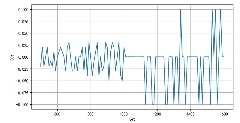
test the error between the set PWM frequency and the actual output frequency. Why this is the case can not be explained now.
the value of arr is adjusted and rounded. In addition, when the ARR is set to about 10000, it can be seen that the error frequency is about 1 / 10000.
※ general ※ conclusion ※
using the mem32 function, for the problem of low PWM frequency accuracy in MM32 micropathon, the PWM frequency accuracy can be improved by readjusting the ARR.
2.1 software code
2.1.1 micro Python program
from machine                import Pin,mem32,PWM
import utime

led = Pin('PB2', Pin.OUT_PUSHPULL)
f = 697
pwm0 = PWM(0, freq=f, duty=500)
pwm1 = PWM(4, freq=f, duty=500)

from micropython            import const
APB2PERIPH_BASE = const(0x40010000)
UART1_BASE    = const(APB2PERIPH_BASE + 0x3800)
UART1_RDR     = const(UART1_BASE + 1*4)
UART1_CSR     = const(UART1_BASE + 2*4)
REPLBUF_LENGTH = const(64)
replbuf = [0]*REPLBUF_LENGTH
replpoint = 0
def procREPL(f):
    global replbuf,replpoint
    if mem32[UART1_CSR] & 0x2:
        bc = mem32[UART1_RDR]
        if replpoint < REPLBUF_LENGTH-1:
            replbuf[replpoint] = bc
            replpoint += 1
        if bc == 13:
            f(bytes(replbuf[0:replpoint-1]))
            replpoint = 0

from micropython            import const
APB1PERIPH_BASE = const(0x40000000)
TIM3_BASE       = const(APB1PERIPH_BASE + 0x0400)
TIM4_BASE       = const(APB1PERIPH_BASE + 0x0800)
TIM_TYPE_CR1    = const(0*4)
TIM_TYPE_CR2    = const(1*4)
TIM_TYPE_SR     = const(4*4)
TIM_TYPE_CNT    = const(9*4)
TIM_TYPE_PSC    = const(10*4)
TIM_TYPE_ARR    = const(11*4)
TIM_TYPE_CCR1   = const(13*4)
TIM_TYPE_CCR2   = const(14*4)
TIM_TYPE_CCR3   = const(15*4)
TIM_TYPE_CCR4   = const(16*4)

def pwmFreq(f, pwm, duty):
    fosc = 96e6
    psc = int(fosc/f/10000) - 1
    arr = int(fosc/(1+psc)/f+0.5)

    if pwm < 4: base = TIM3_BASE
    else:
        base = TIM4_BASE
        pwm -= 4

    mem32[base+TIM_TYPE_PSC] = psc
    mem32[base+TIM_TYPE_ARR] = arr

    ccr = int(arr*duty)
    mem32[base+TIM_TYPE_CCR1+pwm*4]
    return arr

def f(s):
    global pwm0,pwm1
    frq= int(s)
    print(frq)

    pwmFreq(frq, 0, 0.5)
    pwmFreq(frq, 4, 0.5)

while True:
    procREPL(f)
2.1.2 test code
#!/usr/local/bin/python
# -*- coding: gbk -*-
#============================================================
# TEST3.PY                     -- by Dr. ZhuoQing 2022-02-05
#
# Note:
#============================================================
from headm import *                 # =
from tsmodule.tsstm32       import *
setf = range(500, 2000, 10)
outf = []
stm32cmd('SNDCD%d\r'%setf[0])
time.sleep(2)
for f in setf:
    stm32cmd('SNDCD%d\r'%f)
    time.sleep(2)
    meter = meterval()
    outf.append(meter[0])
    printff(f, meter[0])
    tspsave('measure', setf=setf, outf=outf)
delf = [f1-f2 for f1,f2 in zip(setf, outf)]
plt.plot(setf, delf)
plt.xlabel("SetFrequency")
plt.ylabel("Delta Frequency")
plt.grid(True)
plt.tight_layout()
plt.show()
printf('\a')
#------------------------------------------------------------
#        END OF FILE : TEST3.PY
#============================================================
2.1.3 mm32 code
from headm import *                 # =

caretpos = list(tspgetcaretpos())
headspaceself = '\r\n' +  ' '*caretpos[0] + 'self.'
headspace = '\r\n' +  ' '*caretpos[0]
headspaceonly = ' '*caretpos[0]
returnpos = 0

insertstr = ''

if len(sys.argv) > 1:
    if sys.argv[1] == 'repl':
        codestr = (
"from micropython   import const,mem32",
"APB2PERIPH_BASE = const(0x40010000)",
"UART1_BASE    = const(APB2PERIPH_BASE + 0x3800)",
"UART1_RDR     = const(UART1_BASE + 1*4)",
"UART1_CSR     = const(UART1_BASE + 2*4)",
"REPLBUF_LENGTH = const(64)",
"replbuf = [0]*REPLBUF_LENGTH",
"replpoint = 0",
"def procREPL(f):",
"    global replbuf,replpoint",
"    if mem32[UART1_CSR] & 0x2:",
"        bc = mem32[UART1_RDR]",
"        if replpoint < REPLBUF_LENGTH-1:",
"            replbuf[replpoint] = bc",
"            replpoint += 1",
"        if bc == 13:",
"            f(bytes(replbuf[0:replpoint-1]))",
"            replpoint = 0",
"def f(s):",
"    print(int(s))\r\n",
        )
        insertstr = headspace.join(codestr).rstrip(' ')

    elif sys.argv[1] == 'pwmf':
        codestr = (
"from micropython            import const",
"APB1PERIPH_BASE = const(0x40000000)",
"TIM3_BASE       = const(APB1PERIPH_BASE + 0x0400)",
"TIM4_BASE       = const(APB1PERIPH_BASE + 0x0800)",
"TIM_TYPE_CR1    = const(0*4)",
"TIM_TYPE_CR2    = const(1*4)",
"TIM_TYPE_SR     = const(4*4)",
"TIM_TYPE_CNT    = const(9*4)",
"TIM_TYPE_PSC    = const(10*4)",
"TIM_TYPE_ARR    = const(11*4)",
"TIM_TYPE_CCR1   = const(13*4)",
"TIM_TYPE_CCR2   = const(14*4)",
"TIM_TYPE_CCR3   = const(15*4)",
"TIM_TYPE_CCR4   = const(16*4)",
"def pwmFreq(f, pwm, duty):",
"    fosc = 96e6",
"    psc = int(fosc/f/10000) - 1",
"    arr = int(fosc/(1+psc)/f+0.5)",
"    if pwm < 4: base = TIM3_BASE",
"    else:",
"        base = TIM4_BASE",
"        pwm -= 4",
"    mem32[base+TIM_TYPE_PSC] = psc",
"    mem32[base+TIM_TYPE_ARR] = arr",
"    ccr = int(arr*duty)",
"    mem32[base+TIM_TYPE_CCR1+pwm*4]",
"    return arr\r\n",
        )
        insertstr = headspace.join(codestr).rstrip(' ')

    elif sys.argv[1] == 'xxxx':
        codestr = (
        )
        insertstr = headspace.join(codestr).rstrip(' ')

    else:
        printf("Unrecoginized argument.\a")
        exit()

if len(insertstr) > 0:
    clipboard.copy(insertstr)
    tsppasteclipboard()

    if returnpos > 0:
        tspsetcaretpos(caretpos[0], caretpos[1])

printf('\a')
■ links to relevant literature:
- Micro Python transplantation PWM on MindMotion MM32 single chip microcomputer
- Limitations of using mm32 microphoton to generate dual audio signals
- Mm32f3277 micro Python mem function for MCU memory access
● links to relevant charts:
- The error of PWM output frequency between 2000 and 500 Hz is 1.1
- Corresponding frequency error from 500 - 1000
- Figure 1.2.2 theoretical frequency error calculated every 5Hz between 500 ~ 2000Hz
- Corresponding frequency error and ARR value
- Figure 1.4.1 error between setting between 500 and 2000Hz and output frequency
- Figure 1.4.2 setting error of frequency between 500-2000Hz
- Figure 1.4.3 frequency error within 500 - 1600Hz