In the previous section, Arduino+ESP32 drives the GC9A01 circular LCD (one),
We've already ported the arduino GFX library, which includes sample programs for LVGL as well.
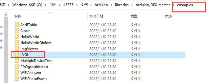
Porting lvgl in arduino is very convenient. Let's transplant one together and run the demo example of lvgl!
Since the Arduino project file in arduino's library path is read-only, it is not easy for us to compile the test sample program, so we copy a sample lvgl program to a folder on my desktop.
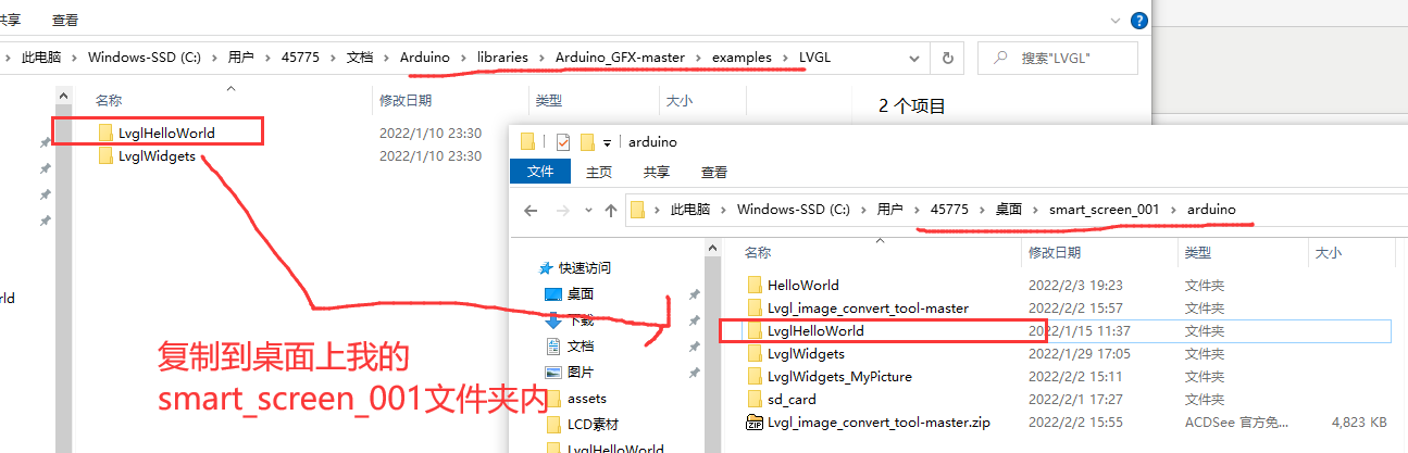
Open LvglHelloWorld.ino project file.
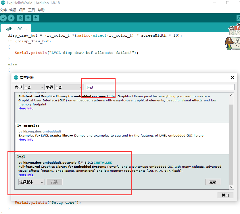
Tools->Management Library->Library Manager, search for LVGL and install it online. I have version 8.0.2 installed, and I recommend that you also install V8 version of LVGL, because the example programs for the arduino GFX library are based on V8 version.
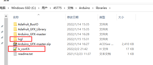
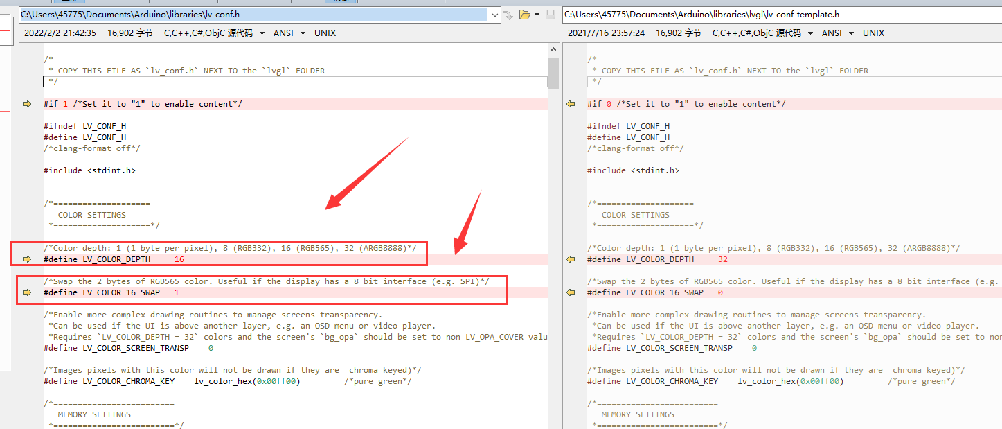
Once LVGL is installed, the lvgl folder appears under the library path. Copy lv_in the lvgl folder Conf_ Template. H, we rename it lv_conf.h, under the library path.
In order for lvgl to fit my hardware LCD, I modified several parameters. Most SPI s or IIC LCDs need to be modified in these places.
Where I modified it (the red arrow points to):
1. Sample program for LVGL running arduino GFX library, LvglHelloWorld
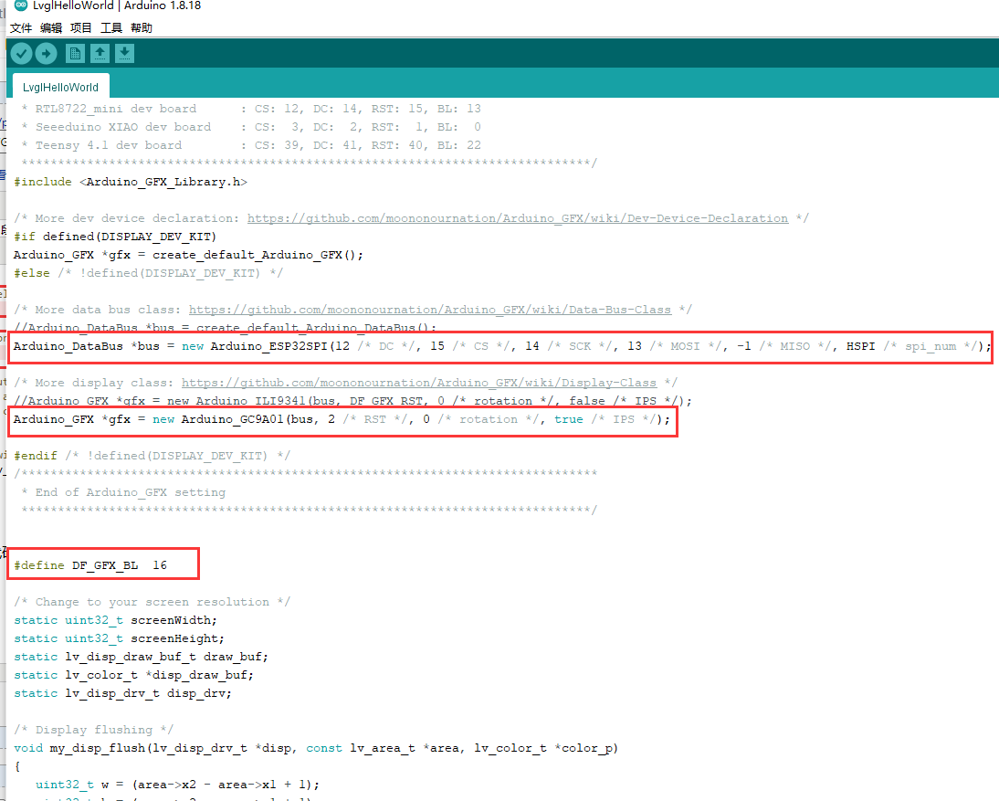
Modify LvglHelloWorld. Three codes for ino project files:
Code source file:
#include <lvgl.h>
/*******************************************************************************
* LVGL Hello World
* This is a simple examplle for LVGL - Light and Versatile Graphics Library
*
* Dependent libraries:
* LVGL: https://github.com/lvgl/lvgl.git
******************************************************************************/
/*******************************************************************************
* Start of Arduino_GFX setting
*
* Arduino_GFX try to find the settings depends on selected board in Arduino IDE
* Or you can define the display dev kit not in the board list
* Defalult pin list for non display dev kit:
* Arduino Nano, Micro and more: CS: 9, DC: 8, RST: 7, BL: 6
* ESP32 various dev board : CS: 5, DC: 27, RST: 33, BL: 22
* ESP32-C3 various dev board : CS: 7, DC: 2, RST: 1, BL: 3
* ESP32-S2 various dev board : CS: 34, DC: 26, RST: 33, BL: 21
* ESP8266 various dev board : CS: 15, DC: 4, RST: 2, BL: 5
* Raspberry Pi Pico dev board : CS: 17, DC: 27, RST: 26, BL: 28
* RTL8720 BW16 old patch core : CS: 18, DC: 17, RST: 2, BL: 23
* RTL8720_BW16 Official core : CS: 9, DC: 8, RST: 6, BL: 3
* RTL8722 dev board : CS: 18, DC: 17, RST: 22, BL: 23
* RTL8722_mini dev board : CS: 12, DC: 14, RST: 15, BL: 13
* Seeeduino XIAO dev board : CS: 3, DC: 2, RST: 1, BL: 0
* Teensy 4.1 dev board : CS: 39, DC: 41, RST: 40, BL: 22
******************************************************************************/
#include <Arduino_GFX_Library.h>
/* More dev device declaration: https://github.com/moononournation/Arduino_GFX/wiki/Dev-Device-Declaration */
#if defined(DISPLAY_DEV_KIT)
Arduino_GFX *gfx = create_default_Arduino_GFX();
#else /* !defined(DISPLAY_DEV_KIT) */
/* More data bus class: https://github.com/moononournation/Arduino_GFX/wiki/Data-Bus-Class */
//Arduino_DataBus *bus = create_default_Arduino_DataBus();
Arduino_DataBus *bus = new Arduino_ESP32SPI(12 /* DC */, 15 /* CS */, 14 /* SCK */, 13 /* MOSI */, -1 /* MISO */, HSPI /* spi_num */);
/* More display class: https://github.com/moononournation/Arduino_GFX/wiki/Display-Class */
//Arduino_GFX *gfx = new Arduino_ILI9341(bus, DF_GFX_RST, 0 /* rotation */, false /* IPS */);
Arduino_GFX *gfx = new Arduino_GC9A01(bus, 2 /* RST */, 0 /* rotation */, true /* IPS */);
#endif /* !defined(DISPLAY_DEV_KIT) */
/*******************************************************************************
* End of Arduino_GFX setting
******************************************************************************/
#define DF_GFX_BL 16
/* Change to your screen resolution */
static uint32_t screenWidth;
static uint32_t screenHeight;
static lv_disp_draw_buf_t draw_buf;
static lv_color_t *disp_draw_buf;
static lv_disp_drv_t disp_drv;
/* Display flushing */
void my_disp_flush(lv_disp_drv_t *disp, const lv_area_t *area, lv_color_t *color_p)
{
uint32_t w = (area->x2 - area->x1 + 1);
uint32_t h = (area->y2 - area->y1 + 1);
gfx->draw16bitBeRGBBitmap(area->x1, area->y1, (uint16_t *)&color_p->full, w, h);
lv_disp_flush_ready(disp);
}
void setup()
{
Serial.begin(115200);
// while (!Serial);
Serial.println("LVGL Hello World");
// Init Display
gfx->begin();
gfx->fillScreen(BLACK);
#ifdef DF_GFX_BL
pinMode(DF_GFX_BL, OUTPUT);
digitalWrite(DF_GFX_BL, HIGH);
delay(100);
#endif
lv_init();
screenWidth = gfx->width();
screenHeight = gfx->height();
disp_draw_buf = (lv_color_t *)malloc(sizeof(lv_color_t) * screenWidth * 10);
if (!disp_draw_buf)
{
Serial.println("LVGL disp_draw_buf allocate failed!");
}
else
{
lv_disp_draw_buf_init(&draw_buf, disp_draw_buf, NULL, screenWidth * 10);
/* Initialize the display */
lv_disp_drv_init(&disp_drv);
/* Change the following line to your display resolution */
disp_drv.hor_res = screenWidth;
disp_drv.ver_res = screenHeight;
disp_drv.flush_cb = my_disp_flush;
disp_drv.draw_buf = &draw_buf;
lv_disp_drv_register(&disp_drv);
/* Initialize the (dummy) input device driver */
static lv_indev_drv_t indev_drv;
lv_indev_drv_init(&indev_drv);
indev_drv.type = LV_INDEV_TYPE_POINTER;
lv_indev_drv_register(&indev_drv);
/* Create simple label */
lv_obj_t *label = lv_label_create(lv_scr_act());
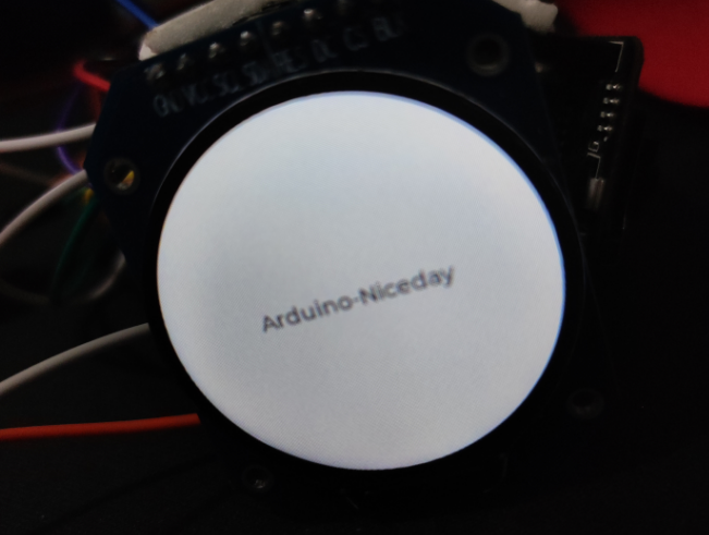
lv_label_set_text(label, "Arduino-Niceday");
lv_obj_align(label, LV_ALIGN_CENTER, 0, 0);
Serial.println("Setup done");
}
}
void loop()
{
lv_timer_handler(); /* let the GUI do its work */
delay(5);
}
Experimental results after burning code
2. Sample code provided by Run lvgl library itself
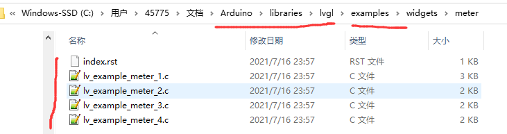
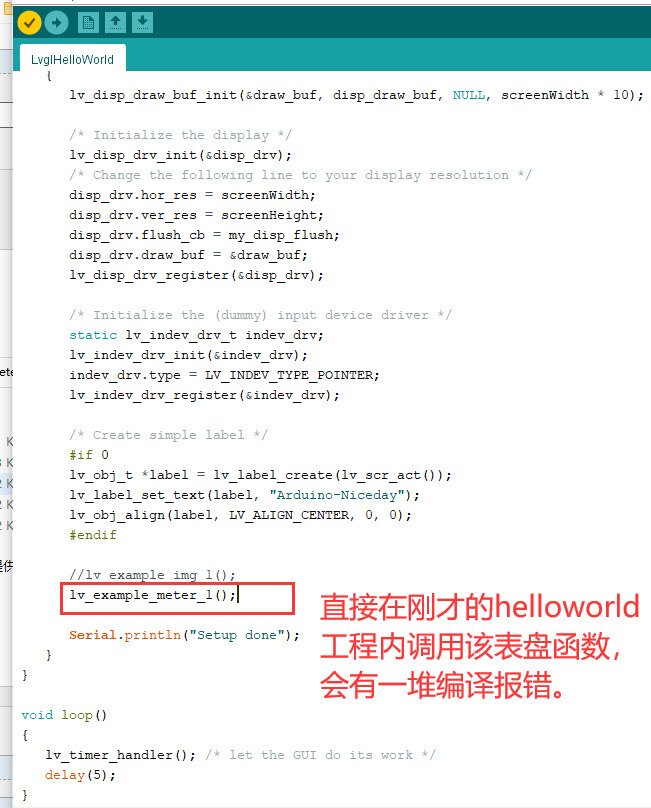
Lvgl itself provides many example s, which are much richer than the LVGL sample programs from arduino GFX library, so we need to run the sample programs provided by lvgl itself to learn lvgl better.
The figure above is an example program of a table.
Baidu found a similar solution

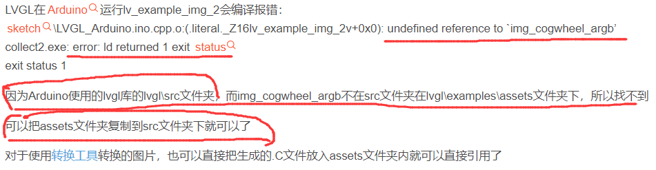
The answer is to copy the files or folders to the lvgl/src path and compile them.
This is a compilation problem, and modifying CMake will certainly solve it as well. Don't study it first. Use this simple way to move folders to get functions. Experience it first.
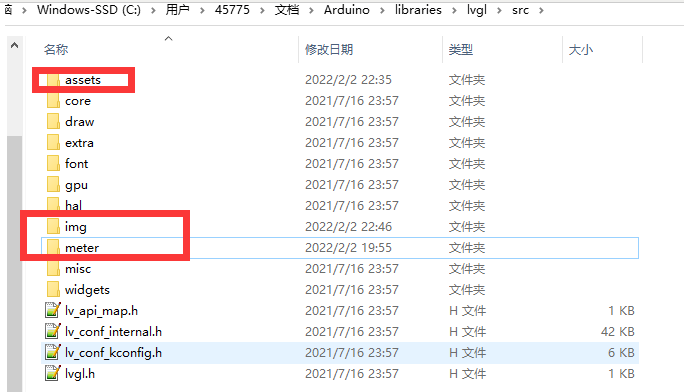
I copied the assets, meter, and img folders from the lvgl/examples folder.
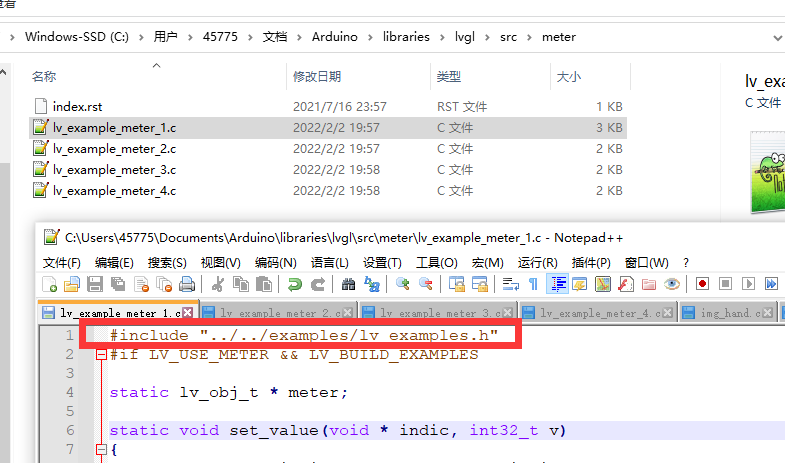
Encountered compilation errors, modified the header file contains to resolve,
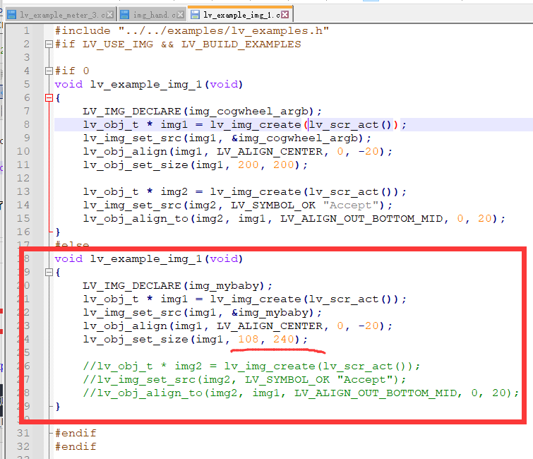
I deleted something in the img folder and modified its code to display my homemade pictures.
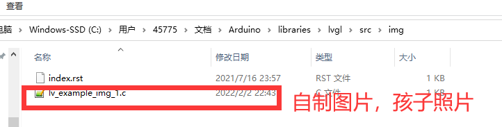
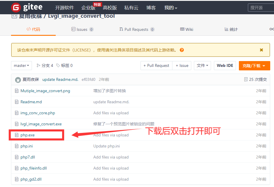
LVGL Picture to C File Tool=" https://gitee.com/gzmarkz/Lvgl_image_convert_tool (
Use Display:
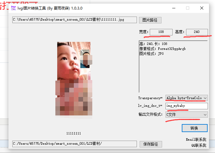
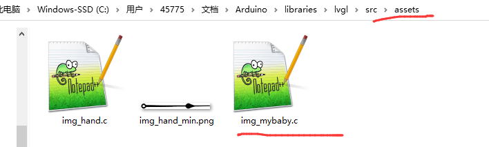
Place the converted C file in the asserts folder.
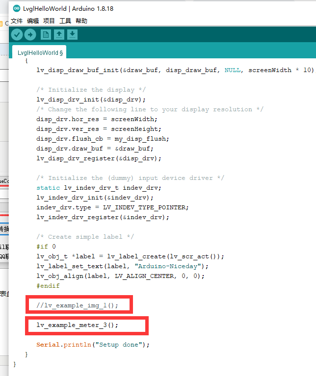
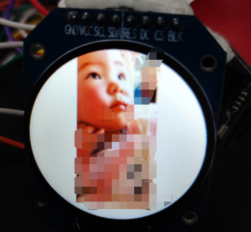
Calling both functions directly in the original project of this article will show different results. A display of my homemade picture, an example of a table showing lvgl.
Experimental results:
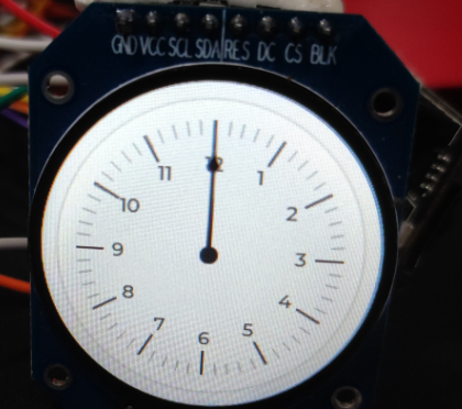
Questions, I see other people's dial example effect, there are two pointers, it will move, my pointer does not move.
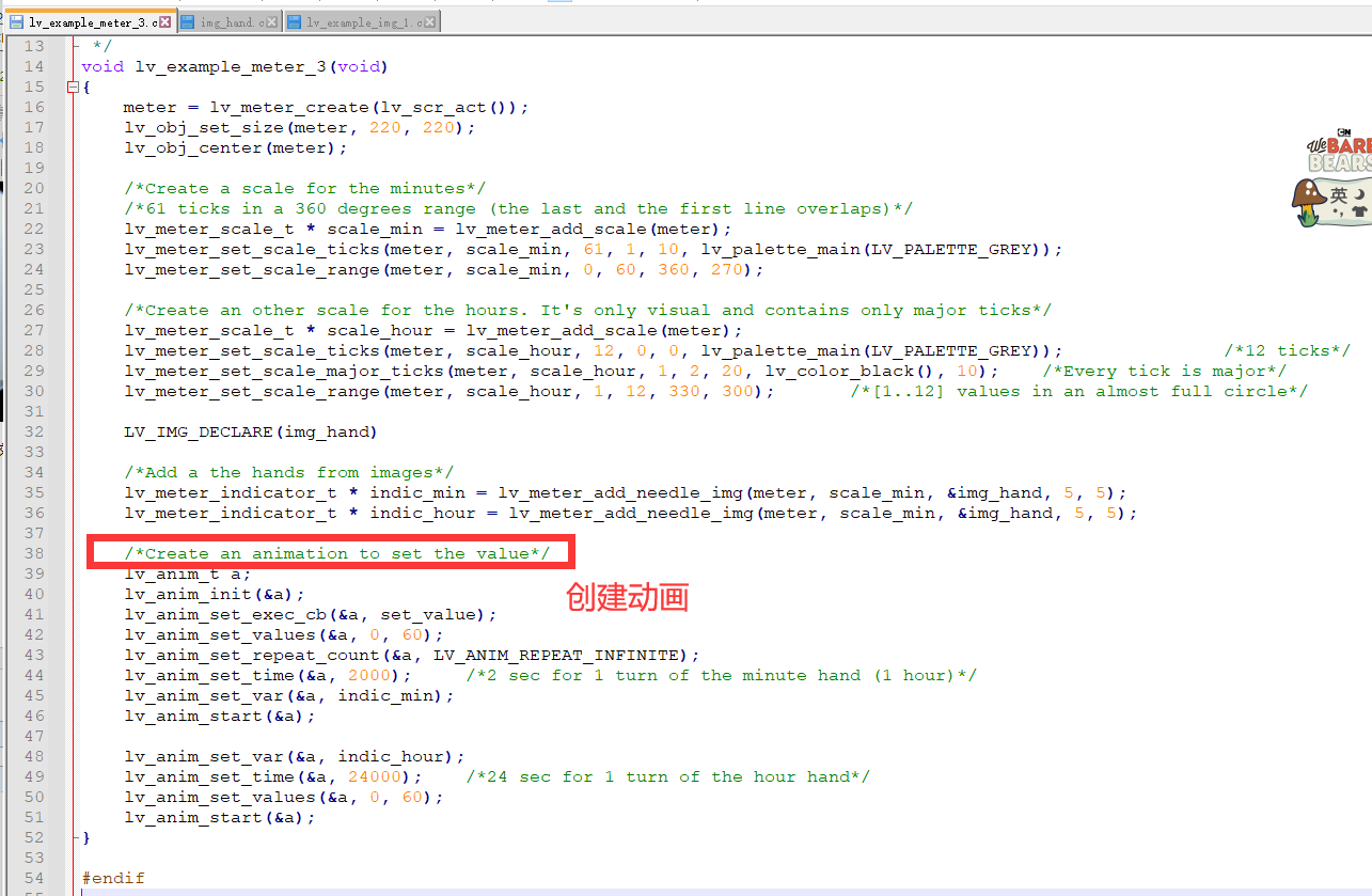
Look at the code, it should be that this part of the animation you created did not achieve the desired effect. Animation function, after LVGL transplantation, did not work properly.
.