Mixed use of various modules
(1) Measurement of temperature and humidity; DHT11
(2) Display of temperature, humidity and other parameters; LCD screen
(3) Setting of alarm data (key); EXIT interrupt service function
(4) Temperature and humidity control; fan, steering gear, heating plate module
(5) Data transmission (wireless communication transmission); ESP8266
(6) Audible and visual alarm reminder. LED, buzzer
Note: This paper has done some extra operations on the ESP8266 code of punctual atom to complete some functions, so as to better understand the application of these modules
Module 1: DHT11
DHT11 is a wet temperature integrated digital sensor. The sensor includes a resistive humidity measuring element and an NTC temperature measuring element, and is connected with a high-performance 8
Bit MCU is connected. Through the simple circuit connection of MCU and other microprocessors, the local humidity and temperature can be collected in real time. DHT11
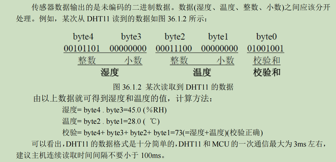
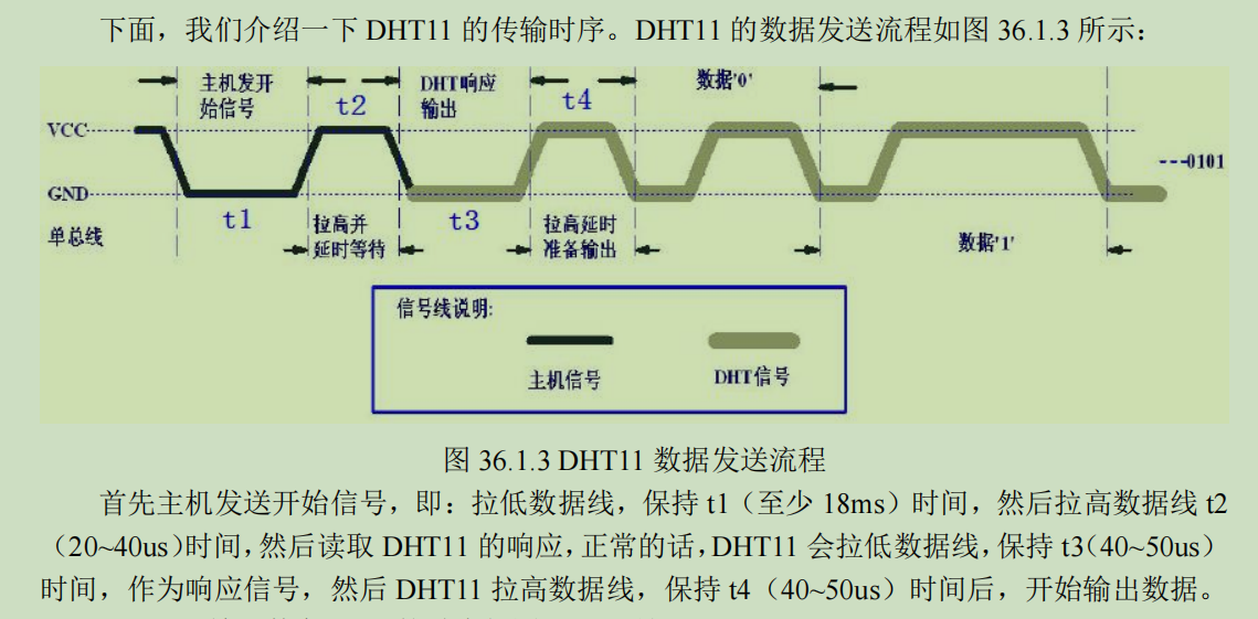
A simple single bus can be used to communicate with MCU, and only one I/O port is needed. Sensor internal humidity and temperature data 40Bit
The data is transmitted to the single chip microcomputer at one time, and the data is verified by checksum to effectively ensure the accuracy of data transmission. The power consumption of DHT11 is very low. Under 5V power supply voltage, the average maximum current of DHT11 works
0.5mA.
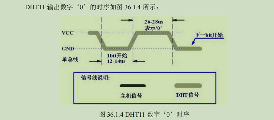
That is, if the high level is pulled up by 26-28us after the low level lasts for 12-14us, it means that this bit is 0.
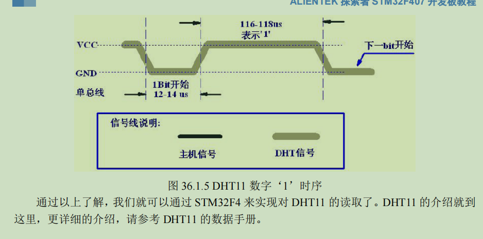
If the high level is pulled up 116-118us after the low level lasts for 12-14us, it means that this bit is 1.
The above is a brief introduction of DHT11. If there is no lack of DHT11 code on the network, it will not be posted. (punctual atom, eternal God)
Module 2: LCD display temperature and humidity
For the configuration of TFTLCD, the punctual atom has been configured for us (ESP8266 code has its own screen). To display the temperature, we must first obtain the temperature, and then display it on the screen through the function. The specific operation is as follows
sprintf((char*)p,"t%s%02dh%s%02dtr%s%02d%02dhr%s%02d%02d\r\n",CHARACTER[0],temperature_t,CHARACTER[0],humidity_t,CHARACTER[0],setval_l,setval_h,CHARACTER[0],setvall_l,setvall_h);//Test data CHARACTER[0] is a = sign
						Show_Str(30+54,100,400,12,p,12,0);
Module 3: setting of alarm value (key control)
We know that since we want to set an alarm for a value, it may exceed a certain value range. Therefore, we need to define the upper and lower limits, and the upper and lower limits can be adjusted, which requires four buttons on the board. So how to change the range by detecting the key? This requires the interrupt service function of the key.
Briefly, some peripherals of STM32 correspond to some interrupt lines. When you configure the IO ports corresponding to these interrupt lines, when these peripherals are detected to be triggered, they will trigger the interrupt service function and enter it to execute the corresponding code. After the code is completed, they will jump out of the service function and continue to execute the following code. It is this that makes it possible to continue to enter the interrupt service function without interfering with the normal operation of the program. The code is as follows:
#include "exti.h"
#include "delay.h"
#include "led.h"
#include "key.h"

//
//This program is only for learning and use, and cannot be used for any other purpose without the permission of the author
//ALIENTEK STM32F407 development board
//External interrupt driver code
//Punctual atom @ ALIENTEK
//Technical Forum: www.openedv.com com
//Created on: May 4, 2014
//Version: V1.0 0
//Copyright, piracy must be prosecuted.
//Copyright(C) Guangzhou Xingyi Electronic Technology Co., Ltd. 2014-2024
//All rights reserved
//

//External interrupt 0 service routine
extern u8 setval_h;
extern u8 setval_l;
extern u8 setvall_h;
extern u8 setvall_l;
void EXTI0_IRQHandler(void)
{
	delay_ms(10);	//Debounce
	if(WK_UP==1)
	{
setvall_h+=2;
	}
	 EXTI_ClearITPendingBit(EXTI_Line0); //Clear the interrupt flag bit on LINE0
}
//External interrupt 2 service program
void EXTI2_IRQHandler(void)
{
	delay_ms(10);	//Debounce
	if(KEY2==0)
	{
setvall_l-=2;
	}
	 EXTI_ClearITPendingBit(EXTI_Line2);//Clear the interrupt flag bit on LINE2
}
//External interrupt 3 service program
void EXTI3_IRQHandler(void)
{
	delay_ms(10);	//Debounce
	if(KEY1==0)
	{

	}
	 EXTI_ClearITPendingBit(EXTI_Line3);  //Clear the interrupt flag bit on LINE3
}
//External interrupt 4 service program
void EXTI4_IRQHandler(void)
{
	delay_ms(10);	//Debounce
	if(KEY0==0)
	{
setval_l+=2;
	}
	 EXTI_ClearITPendingBit(EXTI_Line4);//Clear the interrupt flag bit on LINE4
}

//External interrupt initialization program
//Initialize Pe2 ~ 4 and PA0 as interrupt input
void EXTIX_Init(void)
{
	NVIC_InitTypeDef   NVIC_InitStructure;
	EXTI_InitTypeDef   EXTI_InitStructure;

	KEY_Init(); //Initialization of IO port corresponding to key

	RCC_APB2PeriphClockCmd(RCC_APB2Periph_SYSCFG, ENABLE);//Enable SYSCFG clock


	SYSCFG_EXTILineConfig(EXTI_PortSourceGPIOE, EXTI_PinSource2);//PE2 is connected to interrupt line 2
	SYSCFG_EXTILineConfig(EXTI_PortSourceGPIOE, EXTI_PinSource3);//PE3 is connected to interrupt line 3
	SYSCFG_EXTILineConfig(EXTI_PortSourceGPIOE, EXTI_PinSource4);//PE4 is connected to interrupt line 4
	SYSCFG_EXTILineConfig(EXTI_PortSourceGPIOA, EXTI_PinSource0);//PA0 connected to interrupt line 0

  /* Configure EXTI_Line0 */
  EXTI_InitStructure.EXTI_Line = EXTI_Line0;//LINE0
  EXTI_InitStructure.EXTI_Mode = EXTI_Mode_Interrupt;//Interrupt event
  EXTI_InitStructure.EXTI_Trigger = EXTI_Trigger_Rising; //Rising edge trigger
  EXTI_InitStructure.EXTI_LineCmd = ENABLE;//Enable LINE0
  EXTI_Init(&EXTI_InitStructure);//to configure

	/* Configure EXTI_Line2,3,4 */
	EXTI_InitStructure.EXTI_Line = EXTI_Line2 | EXTI_Line3 | EXTI_Line4;
  EXTI_InitStructure.EXTI_Mode = EXTI_Mode_Interrupt;//Interrupt event
  EXTI_InitStructure.EXTI_Trigger = EXTI_Trigger_Falling; //Falling edge trigger
  EXTI_InitStructure.EXTI_LineCmd = ENABLE;//Interrupt line enable
  EXTI_Init(&EXTI_InitStructure);//to configure

	NVIC_InitStructure.NVIC_IRQChannel = EXTI0_IRQn;//External interrupt 0
  NVIC_InitStructure.NVIC_IRQChannelPreemptionPriority = 0x00;//Preemption priority 0
  NVIC_InitStructure.NVIC_IRQChannelSubPriority = 0x02;//Sub priority 2
  NVIC_InitStructure.NVIC_IRQChannelCmd = ENABLE;//Enable external interrupt channel
  NVIC_Init(&NVIC_InitStructure);//to configure

	NVIC_InitStructure.NVIC_IRQChannel = EXTI2_IRQn;//External interrupt 2
  NVIC_InitStructure.NVIC_IRQChannelPreemptionPriority = 0x03;//Preemption priority 3
  NVIC_InitStructure.NVIC_IRQChannelSubPriority = 0x02;//Sub priority 2
  NVIC_InitStructure.NVIC_IRQChannelCmd = ENABLE;//Enable external interrupt channel
  NVIC_Init(&NVIC_InitStructure);//to configure


	NVIC_InitStructure.NVIC_IRQChannel = EXTI3_IRQn;//External interrupt 3
  NVIC_InitStructure.NVIC_IRQChannelPreemptionPriority = 0x02;//Preemption priority 2
  NVIC_InitStructure.NVIC_IRQChannelSubPriority = 0x02;//Sub priority 2
  NVIC_InitStructure.NVIC_IRQChannelCmd = ENABLE;//Enable external interrupt channel
  NVIC_Init(&NVIC_InitStructure);//to configure


	NVIC_InitStructure.NVIC_IRQChannel = EXTI4_IRQn;//External interrupt 4
  NVIC_InitStructure.NVIC_IRQChannelPreemptionPriority = 0x01;//Preemption priority 1
  NVIC_InitStructure.NVIC_IRQChannelSubPriority = 0x02;//Sub priority 2
  NVIC_InitStructure.NVIC_IRQChannelCmd = ENABLE;//Enable external interrupt channel
  NVIC_Init(&NVIC_InitStructure);//to configure
}
Change the upper and lower temperature limits by detecting the key.
Module 4: temperature and humidity control
Use the fan to cool down, use the heating plate to heat up, and use the steering gear to squeeze the watering can to spray water for humidification.
The fan and heating plate are very simple. They start to work at a given level. The main thing is the configuration and use of the steering gear.
The steering gear receives PWM signal, which can generate a bias voltage in the internal circuit of the steering gear and trigger the motor to drive the potentiometer to move through the reduction gear. When the voltage difference is zero, the motor stops, so as to achieve the effect of servo.
That is, by providing a specific PWM signal to the steering gear, the steering gear can rotate to the specified position.
The frequency of PWM signal received by the steering gear is 50HZ, that is, the period is 20ms. When the pulse width of high level is between 0.5ms-2.5ms, the steering gear can rotate to different angles.
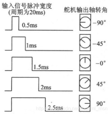
In order to better understand its signal and write code, the PWM key points are converted as follows:
PWM signal cycle: 20000us
At 0 degrees, the high current duration: 500us
At 180 degrees, high level length: 2500us
For every 1 ° increase, it is necessary to increase the high level length: (2500-500) ÷ 180 = 11.1us
For A certain angle value A, the total high-level duration required: (A x11.1 +500)us
Special note: all ms values are converted to us values to facilitate code writing and understanding
--------
Original link: https://blog.csdn.net/zhouml_msn/article/details/116142124
#include "PWM.h"
#include "led.h"

void TIM1_PWM_Init(u32 arr,u32 psc)
{

	GPIO_InitTypeDef GPIO_InitStructure;
	TIM_TimeBaseInitTypeDef  TIM_TimeBaseStructure;
	TIM_OCInitTypeDef  TIM_OCInitStructure;

	RCC_APB2PeriphClockCmd(RCC_APB2Periph_TIM1,ENABLE);  	//TIM1????
	RCC_AHB1PeriphClockCmd(RCC_AHB1Periph_GPIOA, ENABLE); 	//??PORT??

	GPIO_PinAFConfig(GPIOA,GPIO_PinSource8,GPIO_AF_TIM1); //GPIOA8??????1

	GPIO_InitStructure.GPIO_Pin = GPIO_Pin_8|GPIO_Pin_11;           //GPIOF9
	GPIO_InitStructure.GPIO_Mode = GPIO_Mode_AF;        //????
	GPIO_InitStructure.GPIO_Speed = GPIO_Speed_50MHz;	//??100MHz
	GPIO_InitStructure.GPIO_OType = GPIO_OType_PP;      //??????
	GPIO_InitStructure.GPIO_PuPd = GPIO_PuPd_UP;        //??
	GPIO_Init(GPIOA,&GPIO_InitStructure);              //???PA

  TIM_TimeBaseStructure.TIM_Period=arr;   //??????
	TIM_TimeBaseStructure.TIM_Prescaler=psc;  //?????
	TIM_TimeBaseStructure.TIM_CounterMode=TIM_CounterMode_Up; //??????
	TIM_TimeBaseStructure.TIM_ClockDivision=0;  //TIM_CKD_DIV1;
	TIM_TimeBaseInit(TIM1,&TIM_TimeBaseStructure);//??????1

	//???TIM14 Channel1 PWM??
	TIM_OCInitStructure.TIM_OCMode = TIM_OCMode_PWM1; //???????:TIM????????2
 	TIM_OCInitStructure.TIM_OutputState = TIM_OutputState_Enable; //??????
	TIM_OCInitStructure.TIM_OCPolarity = TIM_OCPolarity_Low; //????:TIM???????
	TIM_OC1Init(TIM1, &TIM_OCInitStructure);//??T??????????TIM1 4OC1
	TIM_OC4Init(TIM1, &TIM_OCInitStructure);
	TIM_CtrlPWMOutputs(TIM1,ENABLE);
	TIM_OC1PreloadConfig(TIM1, TIM_OCPreload_Enable);  //??TIM1?CCR1????????
	TIM_OC4PreloadConfig(TIM1, TIM_OCPreload_Enable);

  TIM_ARRPreloadConfig(TIM1,ENABLE);//ARPE??

	TIM_Cmd(TIM1, ENABLE);  //??TIM1
	int main()
	{
TIM1_PWM_Init(200-1,8400-1);	//84M/84=1Mhz counting frequency, reloading value 500, so PWM frequency is
1M/2000=50hz.
}

				TIM_SetCompare1(TIM1,190);           //??0?
                delay_ms(500);
			    TIM_SetCompare1(TIM1,185);           //????45?    (???)
                delay_ms(500);
                TIM_SetCompare1(TIM1,180);           //????90?
                delay_ms(500);
                TIM_SetCompare1(TIM1,175);           //????135?
                delay_ms(500);
                TIM_SetCompare1(TIM1,170);           //????180?
                delay_ms(500);
}
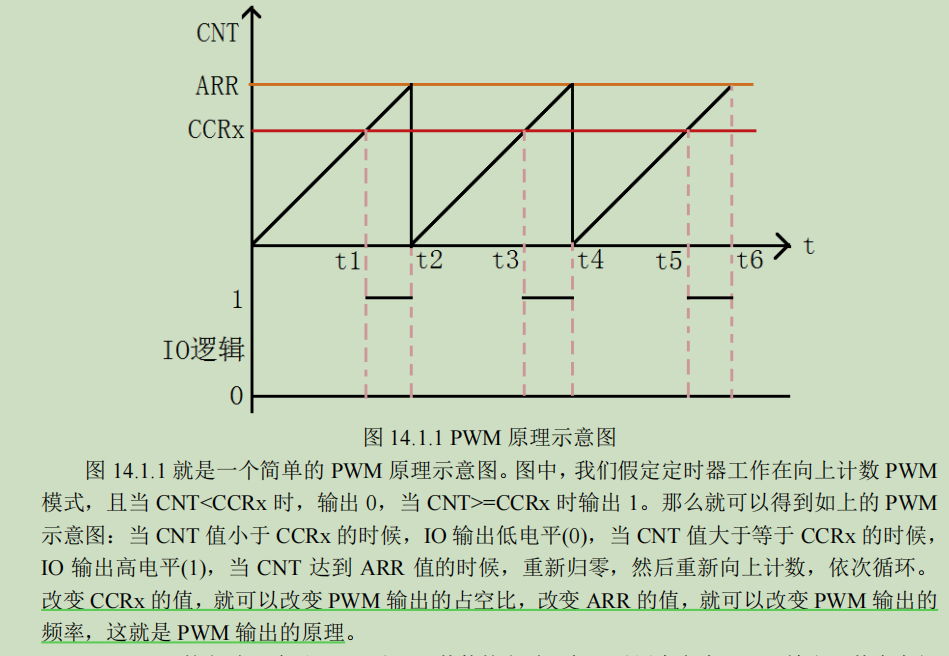
PSC: frequency division coefficient of TIM clock: after the internal clock is divided by PSC value, it is transmitted to CNT counter for use;
CNT: counter, the pulse duration of each CNT count is: 1 ÷ (CLK ÷ PSC)
ARR: automatic reload value: the CNT counter starts counting again after how many pulses. This value can be used to control the required PWM signal period
CCR: used to control the duration of high level in the cycle. When CNT < CCR, it is the effective level The effective level is set through CCER register, and the default effective level is high level Through TIM_SetCompare settings
After knowing the above, suppose we set CCRx to 190 and low-level output, then the low-level time is 190/200*20ms=19ms and the high-level time is 1s. This is the basic configuration of the steering gear.
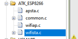
Module 5: ESP8266 WIFI module
I chose to use STA WIFI mode, so we entered the corresponding code section
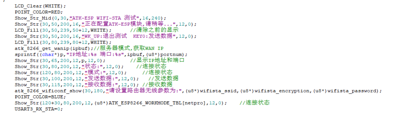
By modifying the code below this code, you can control the corresponding peripherals by sending instructions to the upper computer.
	while(1)
					{
					if(timex==0)    //TCP Server
					{
						DHT11_Read_Data(&temperature_t,&humidity_t);		//Read the temperature and humidity value
						if(setval_l<temperature_t<setval_h||setvall_l<humidity_t<setvall_h)  // 20
						{
						GPIO_ResetBits(GPIOF,GPIO_Pin_9|GPIO_Pin_10);
						//GPIO_SetBits(GPIOF,GPIO_Pin_8);// Buzzer call
							//delay_ms(2000);
							//GPIO_SetBits(GPIOF,GPIO_Pin_8);// Light up
						GPIO_SetBits(GPIOF,GPIO_Pin_8);//  Control buzzer
						}
						//	BEEP_Init();
						//GPIO_ResetBits(GPIOF,GPIO_Pin_8); // The corresponding pin GPIOF8 of buzzer is pulled down,
						//GPIO_ResetBits(GPIOF,GPIO_Pin_9|GPIO_Pin_10);
						sprintf((char*)p,"t%s%02dh%s%02dtr%s%02d%02dhr%s%02d%02d\r\n",CHARACTER[0],temperature_t,CHARACTER[0],humidity_t,CHARACTER[0],setval_l,setval_h,CHARACTER[0],setvall_l,setvall_h);//test data
						Show_Str(30+54,100,400,12,p,12,0);
						atk_8266_send_cmd("AT+CIPSEND=0,25","OK",200);  //Length of data sent
						delay_ms(200);
						atk_8266_send_data(p,"OK",100);  //Send data of specified length
						timex=1000;
						time=0;

					}
				//else
				//	time=time+1;
				if(timex)timex--;
				if(timex==1)LCD_Fill(30+54,100,239,112,WHITE);
				t++;
				delay_ms(10);
				if(USART3_RX_STA&0X8000)		//Received data once
				{
					rlen=USART3_RX_STA&0X7FFF;	//Get the length of the data received this time
					USART3_RX_BUF[rlen]=0;		//Add Terminator
					printf("%s",USART3_RX_BUF);	//Send to serial port
					sprintf((char*)p,"received%d byte,The contents are as follows",rlen);//Bytes received
					LCD_Fill(30+54,115,239,130,WHITE);
					POINT_COLOR=BRED;
					Show_Str(30+54,115,156,12,p,12,0); 			//Displays the length of the received data
					POINT_COLOR=BLUE;
					LCD_Fill(30,130,239,319,WHITE);
					Show_Str(30,130,180,190,USART3_RX_BUF,12,0);//Display received data
					//if(strcmp((const char*)(USART3_RX_BUF+11),"0")==0)LED1=0;  	       // Open LED1
          //if(strcmp((const char*)(USART3_RX_BUF+11),"1")==0)LED1=1;        // Close LED1
					//if(strcmp((const char*)(USART3_RX_BUF+11),"2")==0)LED1=0;        // Open LED1
         // if(strcmp((const char*)(USART3_RX_BUF+11),"1")==0)LED1=1;        // Close LED1
					if(USART3_RX_BUF[11]==0)  //0
					{
					LED0=0; //Light up
					GPIO_SetBits(GPIOF,GPIO_Pin_1);//Gpiof9 and F10 are set high, the light is off and the fan is on

					}
					else if(USART3_RX_BUF[11]==1)  //1
					{
					LED0=1;		//Lights out
					GPIO_ResetBits(GPIOF,GPIO_Pin_1);//Gpiof9 and F10 are set high and the light is off
					}
					else if(USART3_RX_BUF[11]==2)
					{
					LED1=0;
					GPIO_ResetBits(GPIOF,GPIO_Pin_3);//When gpiof9 and F10 are set high, the lamp is off and the heater is turned on
					}
					else if(USART3_RX_BUF[11]==3)
					{
					LED1=1;
					GPIO_SetBits(GPIOF,GPIO_Pin_3);//Gpiof9 and F10 are set high and the light is off
					}
					else if(USART3_RX_BUF[11]==4)			//Equal to 4 water spray
					{		 TIM_SetCompare1(TIM1,190);           //??0?
                delay_ms(500);
								TIM_SetCompare1(TIM1,185);           //????45?    (???)
                delay_ms(500);
                TIM_SetCompare1(TIM1,180);           //????90?
                delay_ms(500);
                TIM_SetCompare1(TIM1,175);           //????135?
                delay_ms(500);
                TIM_SetCompare1(TIM1,170);           //????180?
                delay_ms(500);
                TIM_SetCompare1(TIM1,175);           //????45?,??135????
                delay_ms(500);
                TIM_SetCompare1(TIM1,180);           //?????90????
                delay_ms(500);
                TIM_SetCompare1(TIM1,185);           //??45?
                delay_ms(500);
                TIM_SetCompare1(TIM1,190);           //??0?
                delay_ms(500);
					}
					else;
					USART3_RX_STA=0;
					if(constate!='+')t=1000;		//If the status is not connected, update the connection status immediately
					else t=0;                   //The status is connected. Check again in 10 seconds
				}
				if(t==1000)//No data is received for 10 seconds. Check whether the connection still exists
				{
//			//		LCD_Fill(30+54,125,239,130,WHITE);
//					LCD_Fill(60,80,120,92,WHITE);
					constate=atk_8266_consta_check();//Get connection status
					if(constate=='+')Show_Str(30+30,80,200,12,"Connection successful",12,0);  //Connection status
					else Show_Str(30+30,80,200,12,"connection failed",12,0);
					t=0;
				}
				//if((t%20)==0)LED0=!LED0;
				atk_8266_at_response(1);
			}
Module 6: audible and visual alarm (buzzer, LED)
The configuration of buzzer and LED light is too simple. Just give a level.
Summary:
The above is the whole content. This article only provides some ideas about the nested use of modules. The content is simple. I hope it can be helpful to you.