Binocular stereo vision has always been the development hotspot and difficulty in the field of machine vision research. "Hot" is because binocular stereo vision has its broad application prospects, and with the continuous development of optics, computer science and other disciplines, binocular stereo technology will continue to progress until it is applied to all aspects of human life. "Difficult" is due to the limitations of cameras, lenses and other hardware equipment and some related algorithms. The research of binocular stereo vision and how to better apply it to production practice still need to be broken through.
I brief introduction
Binocular stereo vision is an important branch of machine vision. Since its inception in the mid-1960s, after decades of development, binocular stereo vision is now widely used in robot vision, aerial mapping, military and medical imaging, and industrial detection. Binocular stereo vision is based on the principle of parallax and uses imaging equipment to obtain the left and right images of the measured object from different positions, and then calculates the position deviation of spatial points in the two-dimensional image according to the principle of triangulation, Finally, the position deviation is used for three-dimensional reconstruction to obtain the three-dimensional geometric information of the measured object (the mathematical principle of binocular stereo vision is not introduced in detail in this paper).
II Principle and code implementation of three basic algorithms of binocular stereo vision (based on opencv)
The commonly used region based local matching criteria in binocular stereo vision mainly include SAD (sum of absolute differences), SSD (sum of square differences) and semi global matching algorithm SGM (semi global matching).
2.1 principle of sad (sum of absolute differences)
The basic idea of the matching algorithm SAD is to sum the absolute value of the corresponding pixel difference of the corresponding pixel block of the left and right view image after row alignment.
The mathematical formula is as follows:
The basic flow of SAD matching algorithm is as follows:
① Input two left image and right image that have been corrected to achieve row alignment.
② Scan the left image in the left view, select an anchor point and construct a small window similar to convolution kernel.
③ Use this small window to cover the left image, and select all pixels in the small window coverage area
④ Also use this small window to cover right image, and select all pixels in the small window coverage area.
⑤ Subtract the pixels of the right image coverage area from the pixels of the left image coverage area, and calculate the sum of the absolute values of the differences of all pixels.
⑥ Move the small window of right image and repeat the operations ④ - ⑤ (note that a search range will be set here, and if it exceeds this range, it will jump out)
⑦ Find the small window with the smallest SAD value in this range, and then find the pixel block that best matches the left image anchor.
2.1.1 C + + code implementation of sad (sum of absolute differences) based on opencv
First, define a header file of SAD algorithm (SAD_Algorithm.h):
#include"iostream"
#include"opencv2/opencv.hpp"
#include"iomanip"
using namespace std;
using namespace cv;
class SAD
{
public:
SAD() :winSize(7), DSR(30) {}
SAD(int _winSize, int _DSR) :winSize(_winSize), DSR(_DSR) {}
Mat computerSAD(Mat &L, Mat &R); //Calculate SAD
private:
int winSize; //Size of convolution kernel
int DSR; //Parallax search range
};
Mat SAD::computerSAD(Mat &L, Mat &R)
{
int Height = L.rows;
int Width = L.cols;
Mat Kernel_L(Size(winSize, winSize), CV_8U, Scalar::all(0));
Mat Kernel_R(Size(winSize, winSize), CV_8U, Scalar::all(0));
Mat Disparity(Height, Width, CV_8U, Scalar(0)); //Parallax map
for (int i = 0; i<Width - winSize; i++) //The left figure starts from DSR
{
for (int j = 0; j<Height - winSize; j++)
{
Kernel_L = L(Rect(i, j, winSize, winSize));
Mat MM(1, DSR, CV_32F, Scalar(0));
for (int k = 0; k<DSR; k++)
{
int x = i - k;
if (x >= 0)
{
Kernel_R = R(Rect(x, j, winSize, winSize));
Mat Dif;
absdiff(Kernel_L, Kernel_R, Dif);//Sum of absolute values of difference
Scalar ADD = sum(Dif);
float a = ADD[0];
MM.at<float>(k) = a;
}
}
Point minLoc;
minMaxLoc(MM, NULL, NULL, &minLoc, NULL);
int loc = minLoc.x;
//int loc=DSR-loc;
Disparity.at<char>(j, i) = loc * 16;
}
double rate = double(i) / (Width);
cout << "Completed" << setprecision(2) << rate * 100 << "%" << endl; //Display processing progress
}
return Disparity;
}
Call example:
#include"SAD_Algorithm.h"
int main(int argc, char* argv[])
{
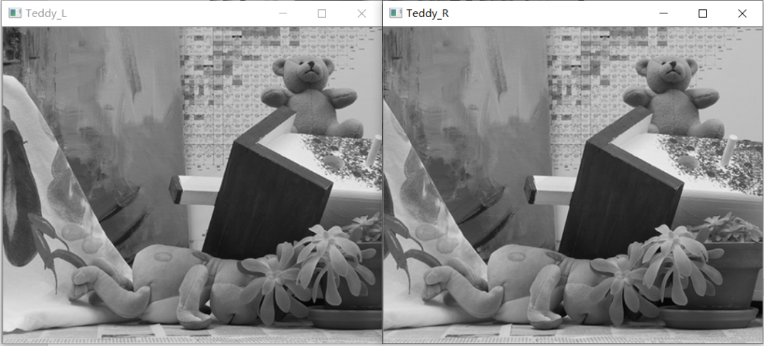
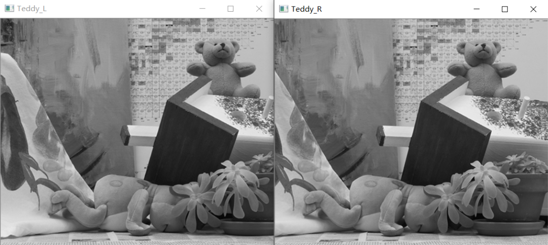
Mat Img_L = imread("Teddy_L.png", 0); //The image called here has been placed in the project folder
Mat Img_R = imread("Teddy_R.png", 0);
Mat Disparity; //Create parallax map
SAD mySAD(7, 30); //Give the parameters of SAD
Disparity = mySAD.computerSAD(Img_L, Img_R);
imshow("Teddy_L", Img_L);
imshow("Teddy_R", Img_R);
imshow("Disparity", Disparity); //Display parallax map
waitKey();
system("pause"); //press any key to exit
return 0;
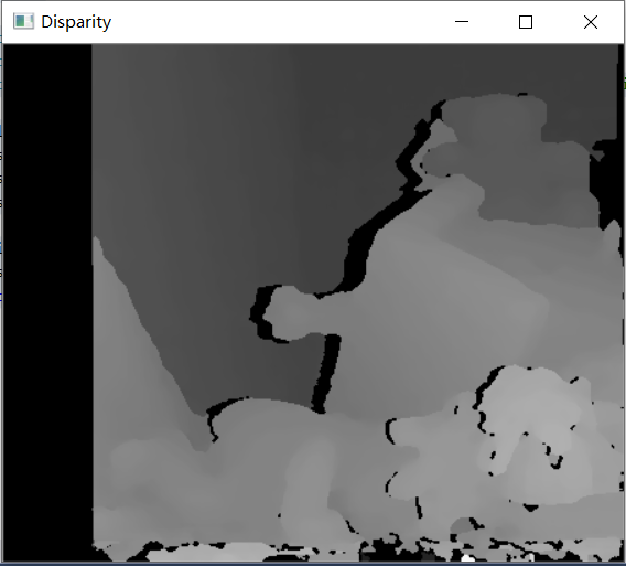
}2.1.2 running effect of sad algorithm
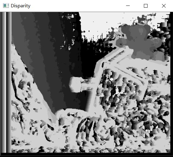
It can be seen that SAD algorithm runs faster, but the effect is poor.
2.2 principle of SSD (sum of squared differences)
SSD (sum of squared differences) algorithm is roughly similar to SAD (sum of absolute differences).
The mathematical formula is as follows:
Because the process and code implementation of SSD matching algorithm are similar to that of SAD matching algorithm, considering the length of space, the basic process and code implementation of SSD algorithm are not repeated in this paper, and readers can implement it by themselves.
2.3 principle of sgbm (semi global block matching)
SGM (semi global matching) is a semi global matching algorithm used to calculate the disparity in binocular stereo vision. Its implementation in opencv is SGBM (semi global block matching).
Principle of SGBM: set a global energy function related to the difference map (composed of the difference of each pixel) to minimize this energy function.
Original document: Heiko hirschmuller Stereo processing by semiglobal matching and mutual information. Pattern Analysis and Machine Intelligence, IEEE Transactions on, 30(2):328–341, 2008.
Its energy function is as follows:
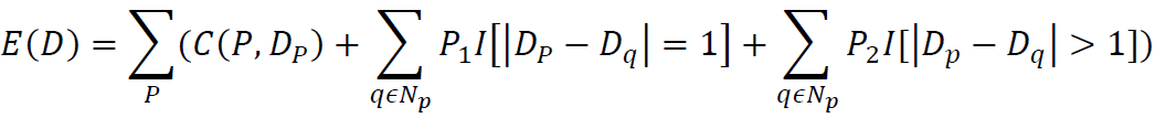
D -- disparity map
p. q - a pixel in the image
Np - pixel point Pd adjacent pixel point (generally considered as 8-connected)
C (P,Dp) -- the cost of the current pixel when its disparity is Dp
P1, P2 - penalty coefficient, which is applicable to when the difference between the difference value between the adjacent pixels of pixel P and the difference value of P is 1 and greater than 1, respectively
I [] - Return 1 when the parameter in [] is true, otherwise return 0
The basic flow of SGBM algorithm is as follows:
① Preprocessing: use sobel operator to process the source image, map the image processed by sobel operator into a new image, and obtain the gradient information of the image for subsequent calculation.
② Cost calculation: use the sampling method to calculate the gradient cost for the preprocessed image gradient information, and use the sampling method to calculate the SAD cost for the source image.
③ Dynamic planning: four paths are selected by default, and the parameters P1 and P2 of path planning are set (including the settings of P1, P2, cn (number of image channels) and SAD window size).
④ Post processing: including uniqueness detection, sub-pixel interpolation, left-right consistency detection and connected area detection.
2.3.1 C + + code implementation of sgbm (semi global block matching) based on opencv
First, define a header file of SGBM algorithm (SGBM_Algorithm.h):
See the code and its notes for specific parameters (if the reader needs to optimize, it can be adjusted by himself), which will not be repeated
enum { STEREO_BM = 0, STEREO_SGBM = 1, STEREO_HH = 2, STEREO_VAR = 3, STEREO_3WAY = 4 };
#include"iostream"
#include"opencv2/opencv.hpp"
using namespace std;
using namespace cv;

void calDispWithSGBM(Mat Img_L, Mat Img_R, Mat &imgDisparity8U)
{
  Size imgSize = Img_L.size();
  int numberOfDisparities = ((imgSize.width / 8) + 15) & -16;
  Ptr<StereoSGBM> sgbm = StereoSGBM::create(0, 16, 3);

  int cn = Img_L.channels();                        //Number of channels for left image
  int SADWindowSize = 9;
  int sgbmWinSize = SADWindowSize > 0 ? SADWindowSize : 3;

  sgbm->setMinDisparity(0);                         //The minimum parallax of minDisparity is 0 by default;

  sgbm->setNumDisparities(numberOfDisparities);     //Numdiscrimination parallax search range, whose value must be an integer multiple of 16;

  sgbm->setP1(8 * cn*sgbmWinSize*sgbmWinSize);
  sgbm->setP2(32 * cn*sgbmWinSize*sgbmWinSize);     //It is generally recommended that the penalty coefficients P1 and P2 take these two values, and P1 and P2 control the smoothness of the parallax map
                                                    //The larger P2, the smoother the parallax map

  sgbm->setDisp12MaxDiff(1);                        //Maximum allowable error threshold of left-right consistency detection

  sgbm->setPreFilterCap(31);                        //The cut-off value of the preprocessing filter, and the output value of the preprocessing is reserved only
                                                    //Values within [- preFilterCap, preFilterCap], parameter range: 1 - 31

  sgbm->setUniquenessRatio(10);                     //Parallax uniqueness percentage: when the lowest cost within the parallax window is (1 + uniquenessRatio/100) times of the second lowest cost
                                                    //The parallax value corresponding to the lowest cost is the parallax of the pixel. Otherwise, the parallax of the pixel is 0 and cannot be negative. Generally, it is 5-15

  sgbm->setSpeckleWindowSize(100);                  //Number of pixels in parallax connected area: for each parallax point, when the number of pixels in its connected area is less than
                                                    //When speckleWindowSize, it is considered that the parallax value is invalid and is noise.

  sgbm->setSpeckleRange(32);                        //Parallax connectivity condition: when calculating the connectivity area of a parallax point, the absolute value of parallax change of the next pixel is greater than
                                                    //speckleRange considers that the next parallax pixel and the current parallax pixel are not connected.

  sgbm->setMode(0);                                 //Mode selection

  sgbm->setBlockSize(sgbmWinSize);                  //Set the SAD cost calculation window, which is generally between 3 * 3 and 21 * 21
                                                    //The smaller the blockSize(SADWindowSize), that is, the smaller the window of matching cost calculation, the greater the parallax noise;
                                                    //The larger the blockSize, the smoother the parallax map;
                                                    //Too large size is easy to lead to over smoothing and more mismatches, which is reflected in the increase of holes in the parallax map

//Three modes (HH, SGBM, 3WAY)
  int algorithm = STEREO_SGBM;

  if (algorithm == STEREO_HH)
    sgbm->setMode(StereoSGBM::MODE_HH);
  else if (algorithm == STEREO_SGBM)
    sgbm->setMode(StereoSGBM::MODE_SGBM);
  else if (algorithm == STEREO_3WAY)
    sgbm->setMode(StereoSGBM::MODE_SGBM_3WAY);

  Mat imgDisparity16S = Mat(Img_L.rows, Img_L.cols, CV_16S);

  sgbm->compute(Img_L, Img_R, imgDisparity16S);

  //--Display it as a CV_8UC1 image: 16 bit signed to 8-bit unsigned
  imgDisparity16S.convertTo(imgDisparity8U, CV_8U, 255 / (numberOfDisparities*16.));
}

Call example:
#include"SGBM_Algorithm.h"
int main()
{
  Mat Img_L = imread("Teddy_L.png", 0);
  Mat Img_R = imread("Teddy_R.png", 0);
  Mat Disparity8U = Mat(Img_L.rows, Img_R.cols, CV_8UC1);//Create a Disparity image

  calDispWithSGBM(Img_L, Img_R, Disparity8U);
  imshow("Teddy_L", Img_L);
  imshow("Teddy_R", Img_R);
  imshow("Disparity", Disparity8U);

  waitKey();
  system("pause");  //press any key to exit
  return 0;
}
2.3.2 operation effect of sgbm algorithm
By the way, I also adjusted the size of SADWindowsize to discuss and show readers the impact of setting different SADWindowsize sizes on the Disparity effect. The results are as follows (all in MODE_SGBM mode):
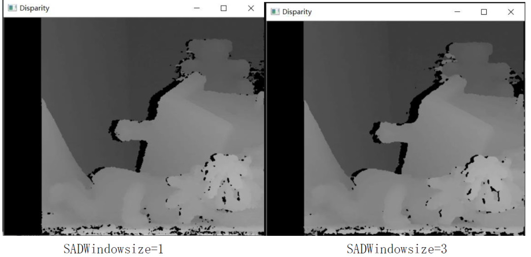
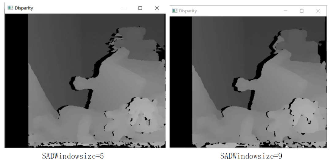
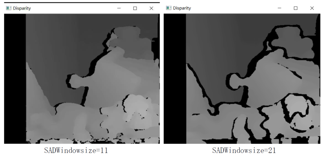
By comparing the above effect pictures with different SADWindowsize settings (other parameters remain unchanged), we can know the following conclusions:
When the SADWindowsize is too small, there is more noise in the parallax map; With the increase of SADWindowsize, the view is smoother, but when the SADWindowsize is too large, the hole phenomenon in the parallax map will increase; Therefore, when selecting the size of SADWindowsize, you should select the appropriate size (it is recommended to select SADWindowsize=9).
III Development status of binocular stereo vision
At present, in foreign countries, binocular stereo vision technology has been widely used in production and life, but in China, binocular stereo vision technology is still in its infancy, and you still need to work hard and strive for innovation.
3.1 development direction of binocular stereo vision
As for the development status and development goal of binocular stereo vision (to achieve universal binocular stereo vision similar to human eyes), it is still a long way to go. I think the further development direction can be summarized as follows:
① Explore new and more universal computing theory and matching algorithm structure to solve the problems of gray distortion, noise interference and geometric distortion.
② Improve the performance of the algorithm, optimize the algorithm and promote the real-time effect as much as possible.
③ Establishing a more effective binocular stereo model can more fully reflect the essential attributes of stereo vision uncertainty, provide more constraint information for matching and reduce the difficulty of stereo matching.
④ Emphasize the constraints of scene and task, and establish the standards and methods of binocular stereo vision system suitable for different scenes and tasks.
3.2 development trends of binocular stereo vision at home and abroad
At present, binocular stereo vision is mainly used in four fields: robot navigation, parameter detection of micromanipulation system, three-dimensional measurement and virtual reality.
At present, in foreign countries, the adaptive Mechanical System Research Institute of Osaka University in Japan has developed an adaptive binocular visual servo system, which uses the principle of binocular stereo vision, such as taking three relatively stationary signs in each image as a reference, calculates the Jacobian short array of the target image in real time, so as to predict the next movement direction of the target, The adaptive tracking of targets with unknown moving mode is realized. The system only requires static reference marks in both images without camera parameters.
The school of information science, Nara University of science and technology, Japan, proposed an augmented reality system (ar) registration method based on binocular stereo vision, which improves the registration accuracy by dynamically modifying the position of feature points.
The University of Tokyo in Japan integrates real-time binocular stereo vision and the overall attitude information of the robot, and develops a dynamic navigation system of the simulation robot, which establishes a real-time map for the robot according to the real-time situation, so as to realize obstacle detection.
Okayama University in Japan has developed a visual feedback system using a stereo microscope to control the micromanipulator using a stereo microscope, two ccd cameras and a micromanipulator, which is used to operate cells, gene injection and micro assembly of clocks.
MIT computer system proposes a new sensor fusion method for intelligent transportation. The radar system provides the approximate range of target depth, uses binocular stereo vision to provide rough target depth information, and combines with the improved image segmentation algorithm to segment the target position in the video image in the high-speed environment.
The University of Washington, in cooperation with Microsoft, has developed a wide baseline stereo vision system for the Mars satellite "Explorer", which enables the "Explorer" to accurately locate and navigate the terrain within thousands of meters on Mars.
The method is suitable for the accurate extraction of three-dimensional image from the mechanical perspective system, especially in the case of mechanical perspective, which only needs less dynamic information, and only uses the principle of two degree of freedom.
Using binocular ccd camera, Weishi image company provides detailed mathematical model and algorithm interface from the aspects of industrial camera internal parameter calibration, lens distortion calibration, stereo matching, feature point segmentation and so on. ccas, its dual target determination software, adopts Zhang Zhengyou plane calibration method, which can realize the applications of robot navigation, parameter detection of micro operation system, three-dimensional measurement and virtual reality.
Based on binocular stereo vision, the Department of electronic engineering of Southeast University proposed a new stereo matching method to minimize the absolute value of gray correlation multi peak parallax, which can accurately measure the three-dimensional spatial coordinates of three-dimensional irregular objects (deflection coils).
Harbin Institute of technology has realized the navigation of fully autonomous soccer robot by using heterogeneous binocular activity vision system. A fixed camera and a camera that can rotate horizontally are installed on the top and middle and lower parts of the robot respectively, which can monitor different azimuth viewpoints at the same time, reflecting the advantage over human vision. Even in the actual game, when other sensors fail, the navigation of fully autonomous soccer robot can still be realized only by binocular coordination.
The Mars 863 project "non-contact measurement of human body's three-dimensional dimension" adopts the principle of "two viewpoint projection grating three-dimensional measurement". The image pair is obtained by two cameras, and the image data is processed by computer. It can not only obtain the feature size required by clothing design, but also obtain the three-dimensional coordinates of any point on the human body image as needed.
IV The author summarizes
Starting from the three most basic matching algorithms of binocular stereo vision, this paper describes its basic principle, steps and opencv code implementation, and summarizes the development trend and current situation of binocular stereo vision, which can be used as a reference for readers. If there are mistakes, please forgive me!