(please keep it - > Author: Luo Bing https://blog.csdn.net/luobing4365)
After introducing all the background knowledge, we can finally enter the substantive embedded programming.
This paper plans to use YIE002 development board to make a USB HID device, which supports three communication modes to correspond to the three host computer communication discussed in UEFI development exploration 73 and 74.
This series of blogs mainly focus on the exploration of UEFI programming. I don't want to discuss too much about embedded programming. For the embedded development of YIE002, please move to my other column "embedded development", in which I opened a new pit to explore the programming of YIE002.
1. USB programming of yie002-stm32
The main chip of this development board is STM32F103C8T6, which is the version I most often take on business trips. For example, the developed chip series of F1 is applicable to all the main boards.
According to the official data of Italy and France, STM32 MCU has the following USB IP:
- USB IP can be used as a full speed USB device and exists in STM32F102 and STM32F103;
- USB+ IP can be used as a full speed USB device and exists in STM32F0x2;
- FS OTG IP can be used as full speed and low-speed USB host and full speed USB device, and exists in STM32F105, STM32F107, STM32F2 and STM32F4;
- HS OTG IP can be used as a high-speed, full speed and low-speed USB host, as a high-speed and full speed USB device, and exists in STM32F2 and STM32F4.
The official also provides different USB libraries to meet the development needs. For example, for USB IP and USB+ IP, the library provided is shown in Figure 1.
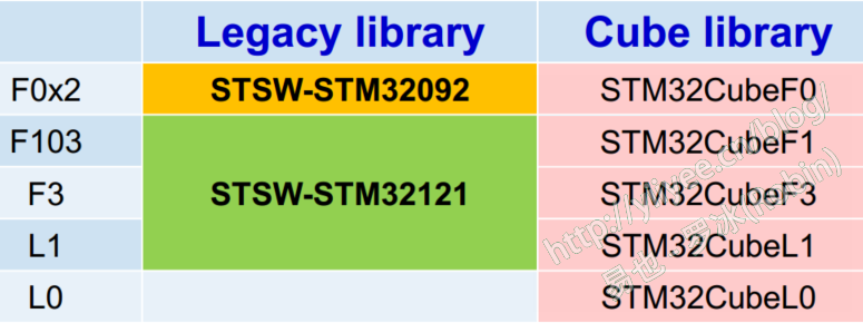
Figure 1 USB library corresponding to USB (+) IP
Therefore, for F103 Series MCU, Legacy library or Cube library can be selected for development.
The development of this article is based on the example project custom of Legacy library_ Hid modification. For the development method of Cube library, you can refer to the column of embedded development in the blog.
2 adjustment example project Custom_HID
I usually develop embedded products, mainly using MDK Keil tool. The example project provided in Legacy library (stsw-stm3211) supports various compilation tools. Of course, it also brings a lot of redundant code I don't need. In addition, due to the sharing of various files of peripheral library and evaluation board, Legacy library organizes a good code structure, but it is cumbersome for me. I can't modify it under the folder of the library every time.
Therefore, I have custom for the example project_ Hid has been adjusted, many unnecessary codes have been deleted, and the code structure has been reorganized.
As shown in Figure 2, it is the adjusted code structure.

Figure 2 adjusted code structure
Another thing to note is the path of the header file, as shown in Figure 3.
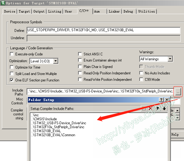
Figure 3 header file contains path
In addition, when selecting equipment, select STM32F103C8 and compile the generated file for YIE002-STM32 development board.
For other details, please compare the project provided by this blog with the original Custom_HID engineering, you can understand.
3 modify code
The process of modifying code mainly includes:
- Prepare various descriptors, including device descriptors, configuration descriptors and report descriptors;
- Realize the code support of three communication modes;
The detailed process is as follows.
3.1 preparation descriptor
The descriptor is mainly in the USB file_ Modified in desc.c. The configuration descriptor is relatively simple. It mainly modifies the manufacturer ID and product ID to the values you need. The main modification is in the configuration descriptor. It should be noted that the endpoint descriptor and interface descriptor are in the same array as the configuration descriptor.
Example 1 configuration descriptor
const uint8_t CustomHID_ConfigDescriptor[CUSTOMHID_SIZ_CONFIG_DESC] =
{
......//Front strategy
/******************** Descriptor of Custom HID endpoints ******************/
    /* 27 */
    0x07,          /* bLength: Endpoint Descriptor size */
    USB_ENDPOINT_DESCRIPTOR_TYPE, /* bDescriptorType: */

    0x81,          /* bEndpointAddress: Endpoint Address (IN) */
    0x03,          /* bmAttributes: Interrupt endpoint */
    0x40,          /* wMaxPacketSize: 64 Bytes max */
    0x00,
    0x20,          /* bInterval: Polling Interval (32 ms) */
    /* 34 */

    0x07,	/* bLength: Endpoint Descriptor size */
    USB_ENDPOINT_DESCRIPTOR_TYPE,	/* bDescriptorType: */
			/*	Endpoint descriptor type */
    0x01,	/* bEndpointAddress: */
			/*	Endpoint Address (OUT) */
    0x03,	/* bmAttributes: Interrupt endpoint */
    0x40,	/* wMaxPacketSize: 64 Bytes max  */
    0x00,
0x20,	/* bInterval: Polling Interval (20 ms) */
}
As can be seen from example 1, the endpoint number for communication is 1, which can be input and output. Two endpoint numbers are used, including the default endpoint 0, so bNumEndpoints must be 2 in the interface descriptor (not listed in example 1).
The report descriptor sets a 16 byte channel, as shown in example 2.
Example 2 report descriptor
const uint8_t CustomHID_ReportDescriptor[CUSTOMHID_SIZ_REPORT_DESC] =
{
	0x05, 0x01, // USAGE_PAGE (Generic Desktop)
	0x09, 0x00, // USAGE (0)
	0xa1, 0x01, // COLLECTION (Application)
	0x15, 0x00, //     LOGICAL_MINIMUM (0)
	0x25, 0xff, //     LOGICAL_MAXIMUM (255)
	0x19, 0x01, //     USAGE_MINIMUM (1)
	0x29, 0x10, //     USAGE_MAXIMUM (16)
	0x95, 0x10, //     REPORT_COUNT (16)
	0x75, 0x08, //     REPORT_SIZE (8)
	0x81, 0x02, //     INPUT (Data,Var,Abs)
	0x19, 0x01, //     USAGE_MINIMUM (1)
	0x29, 0x10, //     USAGE_MAXIMUM (16)
	0x91, 0x02, //   OUTPUT (Data,Var,Abs)
	0x19, 0x01, //     USAGE_MINIMUM (1)
	0x29, 0x10, //     USAGE_MAXIMUM (16)
	0xB1, 0x02, // Feature(Data, Variable, Absolute)
	0xc0        // END_COLLECTION
}; /* CustomHID_ReportDescriptor */
It can be seen that in the constructed channel, the Input report, Output report and Feature report are all 16 bytes long.
3.2 code supporting ReadFile() and WriteFile() methods
USB in source file_ prop. C, modify the communication capability of the endpoint:
  SetEPTxCount(ENDP1, 0x40);   //robin: modified to 64 bytes
  SetEPRxCount(ENDP1, 0x40);   //robin: modified to 64 bytes
Modify the communication function in the source file usb_endp.c, the code is as follows:
uint8_t Receive_Buffer[0xff];
void EP1_OUT_Callback(void)
{
//  BitAction Led_State;
  uint32_t DataLength = 0;
  /* Read received data (2 bytes) */
  DataLength=USB_SIL_Read(EP1_OUT, Receive_Buffer); //Read the data from the endpoint
  SetEPRxStatus(ENDP1, EP_RX_VALID);

  if (Receive_Buffer[0] == 0xA0)//Change the second byte to 1 and return, indicating that it is sent by the endpoint
	{
		Receive_Buffer[1]=0x1;
	}
  USB_SIL_Write(EP1_IN,Receive_Buffer,DataLength);
  SetEPTxStatus(ENDP1,EP_TX_VALID);
}
Other codes do not need to be moved, and USB_ prop. Void customhid under c_ Status_ Comment out all contents in the in (void) function.
So far, the writing of this communication mode has been completed.
3.3 ways to support Input report and Output report, and code of Feature report
In order to support these two communication modes, set needs to be implemented_ Report and Get_Report class command. There are three types of reports: Feature report, Feature report and Output report. The Input report and Output report communicate as Input and Output, and the corresponding upper layer function is HidD_GetInputReport() and HidD_SetOutputReport(); The function corresponding to the upper layer of the Feature report is HidD_GetFeature() and HidD_SetFeature().
All three reports use Set_Report and get_ The report command transmits data only through the wValue in the class command to distinguish the report type: 1 is the Input report, 2 is the Output report, and 3 is the Feature report.
It should be noted that in USB communication, the communication process is viewed from the perspective of the host, and all commands are initiated by the host. Set_ For the device, report is to receive data; Get_ For devices, report is to send data.
The modification process is as follows:
3.3.1 prepare signs and buffers for communication
uint8_t Report_Buf[16];     //Robin: the report length is 16. See the report descriptor
uint8_t Report_InOut_Flag=0; //Robin: Input report and Output report flags
uint8_t Report_Feature_Flag=0;//Robin: Feature report flag
3.3.2 modify RESULT CustomHID_Data_Setup(uint8_t RequestNo)
......
/*** GET_PROTOCOL, GET_REPORT, SET_REPORT ***/
  else if ( (Type_Recipient == (CLASS_REQUEST | INTERFACE_RECIPIENT)) )
  {
    switch( RequestNo )
    {
    case GET_PROTOCOL:
      CopyRoutine = CustomHID_GetProtocolValue;
      break;
    case SET_REPORT:
      CopyRoutine = CustomHID_SetReport_Feature;
      Request = SET_REPORT;
      break;
    //robin add for get_report
    case GET_REPORT:
      if((Report_InOut_Flag==0)&&(Report_Feature_Flag==0))
        return USB_NOT_READY;   //Robin: Inform the host that the data is not ready
      CopyRoutine = CustomHID_GetReport_Feature;
      Request = GET_REPORT;
      break;
    default:
      break;
    }
  }

  if (CopyRoutine == NULL)
  {
    return USB_UNSUPPORT;
  }

  pInformation->Ctrl_Info.CopyData = CopyRoutine;
  pInformation->Ctrl_Info.Usb_wOffset = 0;
  (*CopyRoutine)(0);
  return USB_SUCCESS;
}
That is, get is added_ Report and Set_Report processing function.
3.3.3 modify Get_Report and Set_Report processing function
/*******************************************************************************
* Function Name  : CustomHID_SetReport_Feature
* Description    : Set Feature request handling
* Input          : Length.
* Output         : None.
* Return         : Buffer
*******************************************************************************/
uint8_t *CustomHID_SetReport_Feature(uint16_t Length)
{
  if(pInformation->USBwValues.bw.bb1 == OUT_REPORT)
    Report_InOut_Flag=1;
  else if(pInformation->USBwValues.bw.bb1 == FEATURE_REPORT)
    Report_Feature_Flag=1;

  if (Length == 0)
  {
    pInformation->Ctrl_Info.Usb_wLength = 16;//2; //robin
    return NULL;
  }
  else
  {
//    return Report_Buf;
    return &Report_Buf[pInformation->Ctrl_Info.Usb_wOffset];
  }
}
/*************************************************************************
* Function Name  : CustomHID_GetReport_Feature
* Description    : Set Feature request handling
* Input          : Length.
* Output         : None.
* Return         : Buffer
*************************************************************************/
uint8_t *CustomHID_GetReport_Feature(uint16_t Length)
{
  if(pInformation->USBwValues.bw.bb1 == IN_REPORT)
    Report_InOut_Flag=0;
  else if(pInformation->USBwValues.bw.bb1 == FEATURE_REPORT)
    Report_Feature_Flag=0;

  if (Length == 0) //The length to be sent is reported here
  {
    pInformation->Ctrl_Info.Usb_wLength = 16;//2; //robin
    return NULL;
//    return (uint8_t *)16;
  }
  else  //The data to be processed is returned here
  {
    if(pInformation->USBwValues.bw.bb1 == FEATURE_REPORT)
    {
      if(Report_Buf[0] == 0xA0)
        Report_Buf[1]=0x3;
    }
    else
    {
      if(Report_Buf[0] == 0xA0)
        Report_Buf[1]=0x2;
    }
    return Report_Buf;
  }
}
It is easy to see that different functions are processed for different reports. In order to facilitate the upper computer test, the received data is simply modified locally, and then returned.
4 test
Compile the firmware code, download it to the YIE002 development board, and test it with the upper computer tool, as shown in Figure 4.
Figure 4 testing HID equipment with UsbHID tool
According to the firmware code of HID device and different communication modes, when the first byte is 0xA0, the second byte returned is 0x1, 0x2 and 0x3 respectively. As can be seen from Figure 3, it works normally according to the logic set by the code.
So far, we have completed the writing of USB HID device. Starting from the next article, the HID device will be accessed in the UEFI environment.
Gitee address: https://gitee.com/luobing4365/uefi-exolorer
The project code is located under: / 84 YIE2HID