
This article was originally released by RT thread user @ chengjili and is used to participate in the n32g457 RT thread design competition jointly launched by RT thread and national technology. The original text: https://club.rt-thread.org/as...
This design is used to participate in the innovation "core" engine - national technology n32g457 RT thread design competition. The original intention is that because military products are required to be made domestically, we have been testing the performance, development convenience and most important stability of 32 chips from different domestic manufacturers recently. I have been developing with RTT before. When browsing the official website and finding this competition, I'll take part in it by the way. As for what to do, I can't do anything in my work. All military products are confidential. Can only think of some simple. Just think of the usual test, especially the out test, which is often distressed because of the power problem. So I want to be a simple adjustable voltage source. In this way, I only need to bring a charging treasure to output a voltage of 1~35V, and the peak current can basically reach more than 5A. You can drive most devices. Of course, devices with high power consumption need a large power bank to work for a long time, but at least the problem of power supply voltage mismatch is solved and can be used in emergency.
Since this competition requires the development of the core board given by the official, it is planned to simply realize the main functions first. Later, we will make a specific board to realize the overall function. The test hardware is shown in the figure below. The minimum system board of N32 is added with a board for other tests. This board only uses part of the circuit of LTC3780.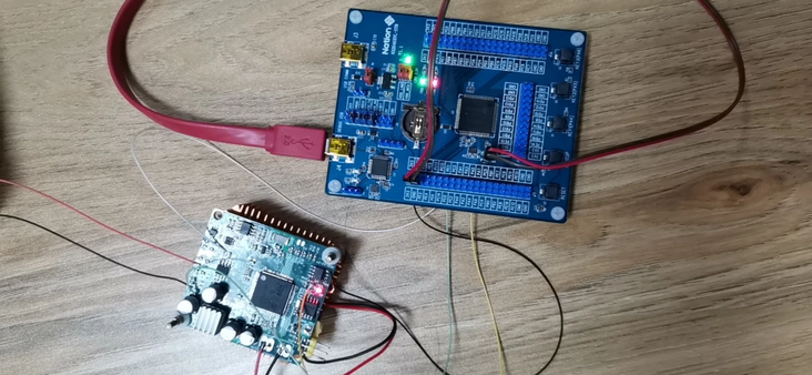
The specific circuit is shown as follows: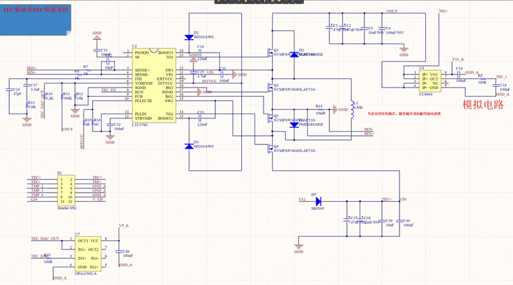
Among them, TEC ground is the final power output interface, TEC_DAC is the output voltage adjustment port, which is connected to PA4 pin of N32 board. TEC_i is the output current detection port, connected to PC1 pin of N32 board. A voltage dividing resistor of 110K and 10K is flying from the power output to the ground, and the voltage dividing short point is connected to the PC0 pin of N32 board to measure the output voltage value (the measured voltage is not calibrated temporarily).
There is no display interface in the beta version (I don't want to connect the fly wire to the screen) 🤣). Instead, the shell interface. The shell command is also used to set the voltage and current values. Later, when making the circuit, it is changed to the interaction between the display screen and the keys and the encoder knob. The test interface is as follows: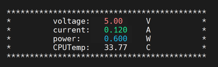
The shell command is implemented to modify the voltage value and current value. ADC acquisition of output voltage and current feedback. Display the current output power in real time. PID control output voltage value. When the current exceeds the current setting value, the current limiting protection is triggered to reduce the voltage. For the function of outputting voltage according to specific waveform, only sinusoidal signal is temporarily. This function needs to be extended to other signals in the future.
In terms of program, I think some drivers of RTT are not very efficient and are only suitable for simple use in specific occasions, or provide a demo. To achieve specific functions, it is recommended to rewrite the underlying driver. For example, the shell underlying serial driver framework and ADC driver framework are used this time. In my daily use, most of them use other system boards to configure the operating parameters of the current board through shell commands. In this way, the amount of data transmitted is much higher than that of manually entering commands. If the bottom processing efficiency is low, there will be the problem of high CPU occupancy when losing data, instructions and serial port configuration parameters. Therefore, to adapt to this situation, I have to rewrite the bottom driver and add the transceiver FIFO. Reading and writing are only for the FIFO interface of the software, without waiting for the real sending and receiving of the hardware, which improves the efficiency of code execution. However, the test functions this time are all manual input of shell commands, so I didn't change this part of the driver, so I used the original one, which is enough for this test demand. But to participate in the competition, you always have to make some contribution to the code, so this time the main change is the underlying driver of ADC, adding some immature understanding of ADC use in your work, hoping to help friends in need. The following is a detailed description:
The following are the official driver, enable ADC channel and the code for reading ADC data:
static rt_err_t n32_adc_enabled(struct rt_adc_device *device, rt_uint32_t channel, rt_bool_t enabled)
{
ADC_Module *n32_adc_handler;
ADC_InitType ADC_InitStructure;
RT_ASSERT(device != RT_NULL);
n32_adc_handler = device->parent.user_data;

n32_msp_adc_init(n32_adc_handler);

ADC_InitStruct(&ADC_InitStructure);
ADC_InitStructure.WorkMode              = ADC_WORKMODE_INDEPENDENT;
ADC_InitStructure.MultiChEn             = DISABLE;
ADC_InitStructure.ContinueConvEn        = DISABLE;
ADC_InitStructure.ExtTrigSelect         = ADC_EXT_TRIGCONV_NONE;
ADC_InitStructure.DatAlign              = ADC_DAT_ALIGN_R;
ADC_InitStructure.ChsNumber             = 1;
ADC_Init(n32_adc_handler, &ADC_InitStructure);

/* ADCx regular channels configuration */
ADC_ConfigRegularChannel(n32_adc_handler, n32_adc_get_channel(channel), 1, ADC_SAMP_TIME_28CYCLES5);

if (((n32_adc_handler == ADC2) || (n32_adc_handler == ADC2))
    && ((n32_adc_get_channel(channel) == ADC_CH_16) || (n32_adc_get_channel(channel) == ADC_CH_18)))
{
    ADC_EnableTempSensorVrefint(ENABLE);
}

/* Enable ADCx */
ADC_Enable(n32_adc_handler, ENABLE);

/* Start ADCx calibration */
ADC_StartCalibration(n32_adc_handler);
/* Check the end of ADCx calibration */
while(ADC_GetCalibrationStatus(n32_adc_handler));

if (enabled)
{
    /* Enable ADC1 */
    ADC_Enable(n32_adc_handler, ENABLE);
}
else
{
    /* Enable ADCx */
    ADC_Enable(n32_adc_handler, DISABLE);
}

return RT_EOK;
}
static rt_err_t n32_get_adc_value(struct rt_adc_device *device, rt_uint32_t channel, rt_uint32_t *value)
{
ADC_Module *n32_adc_handler;

RT_ASSERT(device != RT_NULL);
RT_ASSERT(value != RT_NULL);

n32_adc_handler = device->parent.user_data;

/* Start ADCx Software Conversion */
ADC_EnableSoftwareStartConv(n32_adc_handler, ENABLE);

/* Wait for the ADC to convert */
while(ADC_GetFlagStatus(n32_adc_handler, ADC_FLAG_ENDC) == RESET);

/* get ADC value */
*value = ADC_GetDat(n32_adc_handler);

return RT_EOK;
}
First of all, the initialization ADC in enable has been written to death, the multi-channel acquisition has been turned off, and the continuous conversion has been turned off. Only one channel can be added to the rule group. Therefore, only one channel can be enabled at a time, and the next channel can be enabled after the conversion. Each reading should enable the software to trigger the conversion, and then wait for the conversion to complete, and then read the conversion result and return. This is not an efficient method at present. while waiting, the CPU can't do anything, nor can it schedule to execute the tasks of other threads. It is only suitable for accidentally reading ADC data. Most of the ADC data reading is basically to read a large amount of data, do some smoothing filtering or median filtering, and finally get some stable data. However, it is difficult for this framework to realize this function. Even if one thread is forced to read ADC data frequently to realize this function, it is estimated that the powerful 32 chip can basically do nothing else. The dominant frequency of 144M is not high, but it is not low. There are fpus that can execute some floating-point instructions in parallel. With good use, many things can be completed. It seems that the official ADC driver framework is basically limited to simple demo. So ADC added its own driver as follows:
#define ADC1_BUF1_UPDATE_EVENT      0x00000001
#define ADC1_BUF2_UPDATE_EVENT      0x00000002

#define ADC_VREFINT_VAL             1497.89

#ifdef  BSP_USING_USER_ADC1
 user_adc_config adc1_config =
 {
     .ADC_Handler = ADC1,
     .name        = "user_adc1",
     .RCC_APB2_PERIPH_GPIOX = RCC_APB2_PERIPH_GPIOC,
     .regular_channels = {
             {ADC_CH_18, RT_NULL, RT_NULL},      //rank1 Vrefint
             {ADC_CH_16, RT_NULL, RT_NULL},      //rank2 temp_cup
             {ADC_CH_6, GPIOC, GPIO_PIN_0},      //rank3 out_voltage
             {ADC_CH_7, GPIOC, GPIO_PIN_1}       //rank4 out_current
     }
 };
 uint16_t user_adc1_val_buf[2][USER_ADC1_AVE_N * USER_ADC1_REGULAR_CH];
 float adc1_ave_buf[USER_ADC1_REGULAR_CH-1];
 rt_thread_t adc_data_handle_thread;
 rt_event_t adc_update_event;
#endif

#ifdef  BSP_USING_USER_ADC2
 user_adc_config adc2_config =
 {
     .ADC_Handler = ADC2,
     .name        = "user_adc2",
 };
#endif

void AdcDataHandleEntry(void *parameter);


rt_err_t user_adc_init(rt_device_t dev)
{
 GPIO_InitType GPIO_InitCtlStruct;
 GPIO_InitStruct(&GPIO_InitCtlStruct);
 RT_ASSERT(dev != RT_NULL);
 ADC_Module *ADCx = (ADC_Module *)dev->user_data;
 ADC_InitType ADC_InitStructure;

 adc_update_event = rt_event_create("adc_update", RT_IPC_FLAG_PRIO);

 if(adc_update_event != RT_NULL)
 {
     adc_data_handle_thread = rt_thread_create("adc_data_handle", AdcDataHandleEntry, RT_NULL, 2048, 1, 10);
     if(adc_data_handle_thread != RT_NULL)
         rt_thread_startup(adc_data_handle_thread);
 }

 #ifdef BSP_USING_USER_ADC1
 DMA_InitType ADC1_DMA_InitStructure;
 if(ADCx == ADC1)
 {
      /* ADC1 & GPIO clock enable */
      RCC_EnableAHBPeriphClk(RCC_AHB_PERIPH_ADC1 | RCC_AHB_PERIPH_DMA1, ENABLE);
      ADC_ConfigClk(ADC_CTRL3_CKMOD_AHB,RCC_ADCHCLK_DIV8);
      RCC_EnableAPB2PeriphClk(adc1_config.RCC_APB2_PERIPH_GPIOX, ENABLE);

      ADC_InitStruct(&ADC_InitStructure);
      ADC_InitStructure.WorkMode              = ADC_WORKMODE_INDEPENDENT;
      ADC_InitStructure.MultiChEn             = ENABLE;
      ADC_InitStructure.ContinueConvEn        = ENABLE;
      ADC_InitStructure.ExtTrigSelect         = ADC_EXT_TRIGCONV_NONE;
      ADC_InitStructure.DatAlign              = ADC_DAT_ALIGN_R;
      ADC_InitStructure.ChsNumber             = USER_ADC1_REGULAR_CH;
      ADC_Init(ADCx, &ADC_InitStructure);

      /* Configure ADC Channel as analog input */
      for(int i=0; i<USER_ADC1_REGULAR_CH; i++)
      {
          if(adc1_config.regular_channels[i].channel <= ADC_CH_11)
          {
              GPIO_InitCtlStruct.Pin = adc1_config.regular_channels[i].GPIO_Pin;
              GPIO_InitCtlStruct.GPIO_Speed = GPIO_Speed_2MHz;
              GPIO_InitCtlStruct.GPIO_Mode = GPIO_Mode_AIN;
              GPIO_InitPeripheral(adc1_config.regular_channels[i].GPIOX, &GPIO_InitCtlStruct);
          }
          /* ADCx regular channels configuration */
          ADC_ConfigRegularChannel(ADCx, adc1_config.regular_channels[i].channel, i+1, ADC_SAMP_TIME_239CYCLES5);

          if ((adc1_config.regular_channels[i].channel == ADC_CH_16) || (adc1_config.regular_channels[i].channel == ADC_CH_18))
          {
              ADC_EnableTempSensorVrefint(ENABLE);
          }
      }

      /* Enable ADCx */
      ADC_Enable(ADCx, ENABLE);

      /* Start ADCx calibration */
      ADC_StartCalibration(ADCx);
      /* Check the end of ADCx calibration */
      while(ADC_GetCalibrationStatus(ADCx));

      ADC_Enable(ADCx, ENABLE);

      ADC1_DMA_InitStructure.BufSize = USER_ADC1_AVE_N * USER_ADC1_REGULAR_CH * 2;
      ADC1_DMA_InitStructure.CircularMode = DMA_MODE_CIRCULAR;
      ADC1_DMA_InitStructure.DMA_MemoryInc = DMA_MEM_INC_ENABLE;
      ADC1_DMA_InitStructure.Direction = DMA_DIR_PERIPH_SRC;
      ADC1_DMA_InitStructure.Mem2Mem = DMA_M2M_DISABLE;
      ADC1_DMA_InitStructure.MemAddr = (uint32_t)user_adc1_val_buf;
      ADC1_DMA_InitStructure.MemDataSize = DMA_MemoryDataSize_HalfWord;
      ADC1_DMA_InitStructure.PeriphAddr = &(ADCx->DAT);
      ADC1_DMA_InitStructure.PeriphDataSize = DMA_PERIPH_DATA_SIZE_HALFWORD;
      ADC1_DMA_InitStructure.PeriphInc = DMA_PERIPH_INC_DISABLE;
      ADC1_DMA_InitStructure.Priority = DMA_PRIORITY_MEDIUM;
      DMA_Init(DMA1_CH1, &ADC1_DMA_InitStructure);

      DMA_ConfigInt(DMA1_CH1, DMA_INT_HTX | DMA_INT_TXC, ENABLE);

      ADC_EnableDMA(ADCx, ENABLE);

      DMA_EnableChannel(DMA1_CH1, ENABLE);

      NVIC_SetPriorityGrouping(4);
      NVIC_EnableIRQ(DMA1_Channel1_IRQn);

      ADC_EnableSoftwareStartConv(ADCx, ENABLE);

 }
 #endif

 #ifdef BSP_USING_USER_ADC2
 if(ADCx == ADC2)
 {
      /* ADC2 & GPIO clock enable */
      RCC_EnableAHBPeriphClk(RCC_AHB_PERIPH_ADC2, ENABLE);
      ADC_ConfigClk(ADC_CTRL3_CKMOD_AHB,RCC_ADCHCLK_DIV8);
      RCC_EnableAPB2PeriphClk(RCC_APB2_PERIPH_GPIOC, ENABLE);

      /* Configure ADC Channel as analog input */
      GPIO_InitCtlStruct.Pin = GPIO_PIN_1;
      GPIO_InitCtlStruct.GPIO_Speed = GPIO_Speed_2MHz;
      GPIO_InitCtlStruct.GPIO_Mode = GPIO_Mode_AIN;
      GPIO_InitPeripheral(GPIOC, &GPIO_InitCtlStruct);
 }
 #endif
 return RT_EOK;
}


rt_err_t user_adc_close(rt_device_t dev)
{
 ADC_Module *ADCx = (ADC_Module *)(dev->user_data);
 ADC_Enable(ADCx, DISABLE);
 if(ADCx == ADC1)
 {
     DMA_EnableChannel(DMA1_CH1, DISABLE);
     NVIC_DisableIRQ(DMA1_Channel1_IRQn);
     RCC_EnableAHBPeriphClk(RCC_AHB_PERIPH_ADC1 | RCC_AHB_PERIPH_DMA1, DISABLE);
 }
 rt_thread_delete(adc_data_handle_thread);
 rt_event_delete(adc_update_event);
 dev->flag &= ~(RT_DEVICE_FLAG_ACTIVATED);
 return RT_EOK;
}

static rt_size_t user_adc_read(rt_device_t dev, rt_off_t pos, void *buffer, rt_size_t size)
{
 rt_size_t i;
 user_adc_device_t adc = (user_adc_device_t)dev;
 float *value = (float *)buffer;

 for (i = 0; i < size; i++)
 {
     if(pos+i < USER_ADC1_REGULAR_CH-1)
     {
         value[pos+i] = adc1_ave_buf[pos+i];
     }
     else {
         break;
     }
 }

 return i;
}

static rt_err_t user_adc_control(rt_device_t dev, int cmd, void *args)
{
 rt_err_t result = RT_EOK;
 user_adc_device_t adc = (user_adc_device_t)dev;


 return result;
}

rt_err_t user_hw_adc_register(user_adc_device_t device, const char *name, const void *user_data)
{
 rt_err_t result = RT_EOK;

 device->parent.type = RT_Device_Class_Miscellaneous;
 device->parent.rx_indicate = RT_NULL;
 device->parent.tx_complete = RT_NULL;

 device->parent.init        = user_adc_init;
 device->parent.open        = RT_NULL;
 device->parent.close       = user_adc_close;
 device->parent.read        = user_adc_read;
 device->parent.write       = RT_NULL;
 device->parent.control     = user_adc_control;

 device->parent.user_data = (void *)user_data;

 result = rt_device_register(&device->parent, name, RT_DEVICE_FLAG_RDONLY);

 return result;
}

static int user_hw_adc_init(void)
{
 int result = RT_EOK;
 /* register ADC device */
#ifdef  BSP_USING_USER_ADC1
 if (user_hw_adc_register(&adc1_config.n32_adc_device, adc1_config.name, adc1_config.ADC_Handler) == RT_EOK)
 {
     LOG_D("%s register success", adc1_config.name);
 }
 else
 {
     LOG_E("%s register failed", adc1_config.name);
     result = -RT_ERROR;
 }
#endif

#ifdef  BSP_USING_USER_ADC2
 if (user_hw_adc_register(&adc2_config.n32_adc_device, adc2_config.name, adc2_config.ADC_Handler) == RT_EOK)
 {
     LOG_D("%s register success", adc2_config.name);
 }
 else
 {
     LOG_E("%s register failed", adc2_config.name);
     result = -RT_ERROR;
 }
#endif

 return result;
}
INIT_COMPONENT_EXPORT(user_hw_adc_init);


void DMA1_Channel1_IRQHandler()
{
 if(DMA_GetIntStatus(DMA1_INT_HTX1,DMA1) == SET)
 {
     rt_event_send(adc_update_event, ADC1_BUF1_UPDATE_EVENT);
     DMA_ClrIntPendingBit(DMA1_INT_HTX1, DMA1);
 }
 if(DMA_GetIntStatus(DMA1_INT_TXC1,DMA1) == SET)
 {
     rt_event_send(adc_update_event, ADC1_BUF2_UPDATE_EVENT);
     DMA_ClrIntPendingBit(DMA1_INT_TXC1, DMA1);
 }
}

void GetAdcDataAverage(float *ave_buf, uint16_t *adc_buf)
{
 for(int i=0; i<USER_ADC1_REGULAR_CH-1; i++)
 {
     float adc_sum=0;
     for(int j=0; j<USER_ADC1_AVE_N; j++)
     {
         adc_sum += ADC_VREFINT_VAL * adc_buf[j*USER_ADC1_REGULAR_CH+i+1] / adc_buf[j*USER_ADC1_REGULAR_CH];
     }
     ave_buf[i] = adc_sum / USER_ADC1_AVE_N;
 }
}

void AdcDataHandleEntry(void *parameter)
{
 rt_uint32_t recved_event;
 while(1)
 {
     if(RT_EOK == rt_event_recv(adc_update_event, ADC1_BUF1_UPDATE_EVENT | ADC1_BUF2_UPDATE_EVENT, RT_EVENT_FLAG_OR | RT_EVENT_FLAG_CLEAR, -1, &recved_event))
     {
         if(recved_event & ADC1_BUF1_UPDATE_EVENT)
         {
             GetAdcDataAverage(adc1_ave_buf, user_adc1_val_buf[0]);
         }
         if(recved_event & ADC1_BUF2_UPDATE_EVENT)
         {
             GetAdcDataAverage(adc1_ave_buf, user_adc1_val_buf[1]);
         }
     }
 }
}
The general idea of the code is to call RT_ device_ When the open function opens the device, initialize the ADC through the Init function here and start the DMA. The amount of ADC data acquisition per channel used here is 100. After half of the data transmission is completed by using the DMA interrupt function, half of the data transmission is completed. In this way, data processing and DMA transmission can be performed in parallel. Send the corresponding event in DMA interrupt. Start a high priority thread, block the event waiting for DMA transmission completion, and process the corresponding data respectively. There is no median filter here, only a simple average filter. After testing, the frequency of collecting ADC data is about 142 frames / S. That is, a set of filtered ADC data is generated in about 7ms. You can modify the sampling time and average points according to your needs. I plan to use 10ms for the PID thread for output voltage regulation, so it is controlled within 10ms. Ensure that there are new data for each PID operation.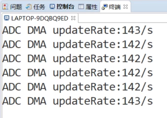
The ADC rule group I use adds four channels. The first channel is CH18, viz. Vreint. The second channel is CH16. The CPU temperature is measured. Finally, the temperature of the whole circuit board is measured. According to the circuit board temperature, the cooling fan is driven to control the cooling. Finally, whether to use CPU temperature control or lay a thermistor next to the heating device will be determined later. Here, because the minimum system board and the power board are separated, the CPU temperature can not measure the temperature of the heating device. So it's just a simple acquisition and display. The third channel is PC0 pin, which is used to collect the feedback of voltage output. The fourth channel is PC1 pin, which is used to collect current feedback. There is no sampling resistance on the test board, but a Hall sensor with a range of ± 10A is used. So the accuracy is a little poor. In the end, there is no need to use this chip. It is planned to use the sampling resistor for the final board. N32 has its own operational amplifier, which can directly amplify the input to ADC for acquisition.
The specific ADC data processing is to compensate the 4-channel data collected in each cycle according to the internal reference voltage according to the theory that the power ripple has little difference in a short time. In this way, the voltage calculated according to ADC data is accurate. The measured data here are as follows: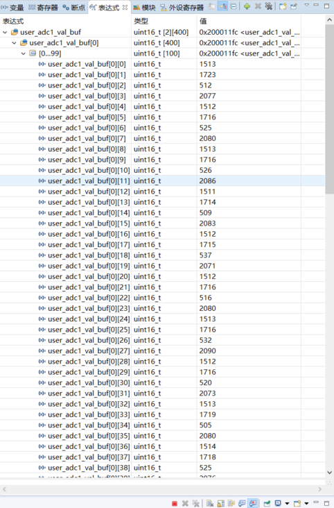
0,4,8,12 of the array It is the saved ADC data of vreint collected in real time, and the power supply voltage of VrefP at this time is 3.265V. It can be calculated that the actual voltage of vreint is 1.2068. The figure below shows the voltage range of vreint officially given.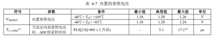
According to the actual vreint, it can be calculated that the ADC conversion value of vreint is 1497.89 when the VrefP power supply voltage is the standard 3.3V power supply. I think the default configuration has enabled FPU, so floating point numbers are directly used here to improve the accuracy.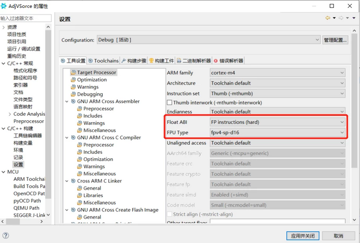
The following is main C implementation of the specific application code. Relatively simple, a voltage control thread is created. Since the voltage regulation has almost no lag for the control cycle of 10ms, the PID control here actually uses only PI.
#define LED1_PIN    90
#define LED2_PIN    91
#define LED3_PIN    67

#define CPU_Avg_Slope   -4.1
#define CPU_V25         1.33

uint16_t test_val=0;
uint8_t print_buf[128];

float read_adc_buf[USER_ADC1_REGULAR_CH-1];

rt_device_t OpenADCDevice(char *name);
rt_device_t adc1_dev=RT_NULL;
rt_device_t dac_dev=RT_NULL;

rt_tick_t shell_getchr_tick;
rt_thread_t voltage_ctrl_thread;
void VoltageCtrlEntry(void *parameter);

void plot_ui()
{
    rt_kprintf("\033[2J");
    rt_kprintf("\033[10;0H");
    rt_kprintf("    *******************************************\r\n");
    rt_kprintf("    *         voltage:");
    rt_kprintf("\033[1;40;31m%s\033[0m","   00.00");
    rt_kprintf("    V           *\r\n");
    rt_kprintf("    *         current:");
    rt_kprintf("\033[1;40;32m%s\033[0m","   0.000");
    rt_kprintf("    A           *\r\n");
    rt_kprintf("    *         power:  ");
    rt_kprintf("\033[1;40;34m%s\033[0m","   00.00");
    rt_kprintf("    W           *\r\n");
    rt_kprintf("    *         CPUTemp:   00.00    C           *\r\n");
    rt_kprintf("    *******************************************\r\n");
    rt_kprintf("\033[20;0H");
}

int main(void)
{
    rt_err_t result;
    uint32_t Speed = 500;
    /* set LED1 pin mode to output */
    rt_pin_mode(LED1_PIN, PIN_MODE_OUTPUT);
    rt_pin_mode(LED2_PIN, PIN_MODE_OUTPUT);
    rt_pin_mode(LED3_PIN, PIN_MODE_OUTPUT);


    adc1_dev = OpenADCDevice("user_adc1");

    voltage_ctrl_thread = rt_thread_create("VoltageCtrl", VoltageCtrlEntry, RT_NULL, 2048, 5, 10);
    if(voltage_ctrl_thread != RT_NULL)
        rt_thread_startup(voltage_ctrl_thread);

    plot_ui();


    while (1)
    {
        rt_pin_write(LED1_PIN, PIN_LOW);
        rt_pin_write(LED2_PIN, PIN_LOW);
        rt_pin_write(LED3_PIN, PIN_LOW);
        rt_thread_mdelay(Speed);
        rt_pin_write(LED1_PIN, PIN_HIGH);
        rt_pin_write(LED2_PIN, PIN_HIGH);
        rt_pin_write(LED3_PIN, PIN_HIGH);
        rt_thread_mdelay(Speed);


    }
}

rt_device_t OpenADCDevice(char *name)
{
    rt_err_t result;
    rt_device_t adc_dev = rt_device_find(name);
    if(adc_dev != RT_NULL)
    {
        if(adc_dev->open_flag == RT_DEVICE_OFLAG_CLOSE)
        {
            result = rt_device_open(adc_dev, RT_DEVICE_OFLAG_RDONLY);
            if(result == RT_EOK)
            {
                rt_kprintf("%s opened!\r\n",name);
            }
            else {
                rt_kprintf("%s open err:%d!\r\n",name,result);
            }
        }
        else {
            rt_kprintf("%s is already opened!\r\n",name);
        }
    }
    else {
        rt_kprintf("not find %s device!\r\n",name);
    }
    return adc_dev;
}
void OpenADC1Device()
{
    adc1_dev = OpenADCDevice("user_adc1");
}
MSH_CMD_EXPORT(OpenADC1Device, open adc1 device and start adc1 conversion);

rt_err_t CloseADCDevice(char *name)
{
    rt_err_t result;
    rt_device_t adc_dev = rt_device_find(name);
    if(adc_dev != RT_NULL)
    {
        result = rt_device_close(adc_dev);
        if(result == RT_EOK)
        {
            rt_kprintf("%s closed!\r\n",name);
        }
        else {
            rt_kprintf("%s close err:%d!\r\n",name,result);
        }
    }
    else {
        rt_kprintf("not find %s device!\r\n",name);
    }
    return result;
}
void CloseADC1Device()
{
    CloseADCDevice("user_adc1");
}
MSH_CMD_EXPORT(CloseADC1Device, close adc1 device and stop adc1 conversion);

void ReadADC1Val()
{
    if(adc1_dev != RT_NULL && adc1_dev->open_flag != RT_DEVICE_OFLAG_CLOSE)
    {
        rt_device_read(adc1_dev, 0, read_adc_buf, USER_ADC1_REGULAR_CH-1);

        sprintf(print_buf, "ADC:%f,%f,%f,%f\r\n", read_adc_buf[0], read_adc_buf[1], read_adc_buf[2], read_adc_buf[3]);
        rt_kprintf(print_buf);
    }
    else {
        rt_kprintf("user_adc1 dev not opened!\r\n");
    }
}
MSH_CMD_EXPORT(ReadADC1Val, read adc1 all channel val);


void get_shell_getchr_tick()
{
    shell_getchr_tick = rt_tick_get();
}

float SetVoltageVal = 5.0;      //V

float SetCurrentVal = 3.0;         //A

float VoltagePID_P = 100;
float VoltagePID_I = 50;

float user_atof(char *str)
{
    float val;
    char *ch_p=RT_NULL;
    do{
        if(*str == 0)
            return 0;
        if(*str == ' ')
        {
            str++;
        }
        else {
            break;
        }
    }
    while(1);
    ch_p = strchr(str , '.');
    int valH = atoi(str);
    float valL=0;
    if(ch_p > 0)
        valL = atoi(ch_p+1);
    do{
        if(valL >= 1)
        {
            valL /= 10;
        }
        else {
            break;
        }
    }while(1);
    val = valH + valL;
    return val;
}

float Sin_vpp=0, Sin_offset=0, Sin_cycle=0, Singal_Cycle_step=0;
void EnSinOut(int argc, char **argv)
{
    if(argc >= 2)
    {
        if(*argv[1] == '?')
        {
            sprintf(print_buf,"Vpp:%f, Offset:%f, Cycle:%f\r\n", Sin_vpp, Sin_offset, Sin_cycle);
            rt_kprintf(print_buf);
        }
        else if(argc >= 4)
        {
            float val = user_atof(argv[1]);
            if(val >=0 && val <=35)
            {
                Sin_vpp = val;
            }
            else {
                sprintf(print_buf,"Error:Out range[0,35]! Vpp:%fV\r\n", Sin_vpp);
                rt_kprintf(print_buf);
            }
            val = user_atof(argv[2]);
            if(val >=0 && val <=35)
            {
                Sin_offset = val;
            }
            else {
                sprintf(print_buf,"Error:Out range[0,35]! Offset:%fV\r\n", Sin_offset);
                rt_kprintf(print_buf);
            }
            val = user_atof(argv[3]);
            if(val >=1 && val <=100)
            {
                Sin_cycle = val;
                Singal_Cycle_step = 2*3.1415926/100/Sin_cycle;
            }
            else {
                sprintf(print_buf,"Error:Out range[1,100]! Cycle:%fS\r\n", Sin_cycle);
                rt_kprintf(print_buf);
            }
            sprintf(print_buf,"Vpp:%fV, Offset:%fV, Cycle:%fS\r\n", Sin_vpp, Sin_offset, Sin_cycle);
            rt_kprintf(print_buf);
        }
        else {
            rt_kprintf("EnSinOut [vpp offset cycle]\r\n");
        }
    }
    else {
        rt_kprintf("EnSinOut [vpp offset cycle]\r\n");
    }
}
MSH_CMD_EXPORT(EnSinOut, enable sinusoidal signal out);

void SetVoltage(int argc, char **argv)
{
    if(argc >= 2)
    {
        if(*argv[1] == '?')
        {
            sprintf(print_buf,"SetVoltageVal:%f\r\n", SetVoltageVal);
            rt_kprintf(print_buf);
        }
        else {
            float val = user_atof(argv[1]);
            if(val >=0 && val <=35)
            {
                Sin_vpp = 0;
                SetVoltageVal = val;
                sprintf(print_buf,"SetVoltageVal:%f\r\n", SetVoltageVal);
                rt_kprintf(print_buf);
            }
            else {
                sprintf(print_buf,"Error:Out range[0,35]! SetVoltageVal:%f\r\n", SetVoltageVal);
                rt_kprintf(print_buf);
            }
        }
    }
    else {
        rt_kprintf("SetVoltage [val]\r\n");
    }
}
MSH_CMD_EXPORT(SetVoltage, set voltage val);

void SetCurrent(int argc, char **argv)
{
    if(argc >= 2)
    {
        if(*argv[1] == '?')
        {
            sprintf(print_buf,"SetCurrentVal:%f\r\n", SetCurrentVal);
            rt_kprintf(print_buf);
        }
        else {
            float val = user_atof(argv[1]);
            if(val >=0 && val <=5)
            {
                SetCurrentVal = val;
                sprintf(print_buf,"SetCurrentVal:%f\r\n", SetCurrentVal);
                rt_kprintf(print_buf);
            }
            else {
                sprintf(print_buf,"Error:Out range[0,5]! SetCurrentVal:%f\r\n", SetCurrentVal);
                rt_kprintf(print_buf);
            }
        }
    }
    else {
        rt_kprintf("SetCurrent [val]\r\n");
    }
}
MSH_CMD_EXPORT(SetCurrent, set current val);


void VoltageCtrlEntry(void *parameter)
{
    uint8_t wait_i=0, replot_flag=0, overcurrent_flag=0;
    float cpu_temp_ave=0, voltage_ave=0, current_ave=0;
    dac_dev = rt_device_find("dac");
    uint32_t ch = 1;
    int32_t dac_val = 4095;
    rt_device_control(dac_dev, RT_DAC_CMD_ENABLE, &ch);
    rt_device_open(dac_dev, RT_DEVICE_OFLAG_RDWR);
    rt_device_write(dac_dev, ch, &dac_val, 1);

    float Voltage_err=0, Voltage_err_old=0, Voltage_err_sum=0;

    float CtrlVoltage=0;

    float Singal_Cycle_i=0;

    rt_thread_sleep(100);
    while(1)
    {
        if(adc1_dev != RT_NULL && adc1_dev->open_flag != RT_DEVICE_OFLAG_CLOSE)
        {
            rt_device_read(adc1_dev, 0, read_adc_buf, USER_ADC1_REGULAR_CH-1);
            float cpu_temp = (CPU_V25 - read_adc_buf[0] * 3.3 / 4096) * 1000 / CPU_Avg_Slope + 25;
            float voltage = read_adc_buf[1] * 3.3 / 4096 * 12;
            float current = -(read_adc_buf[2] * 3.3 / 4096 - 1.65)/0.132;
            if(current < 0)
                current = 0;

            if(Sin_vpp > 0.0001)        //Enable sinusoidal signal output
            {
                Singal_Cycle_i = fmod(Singal_Cycle_i + Singal_Cycle_step, 2*3.1415926);
                SetVoltageVal = Sin_offset + Sin_vpp / 2 * sin(Singal_Cycle_i);
            }

            if(current <= SetCurrentVal)
            {
                if(overcurrent_flag)
                {
                    if(CtrlVoltage < SetVoltageVal-0.1)
                    {
                        CtrlVoltage += 0.1;
                    }
                    else if(CtrlVoltage > SetVoltageVal+0.1)
                    {
                        CtrlVoltage -= 0.1;
                    }
                    else {
                        CtrlVoltage = SetVoltageVal;
                        overcurrent_flag = 0;
                    }
                }
                else {
                    CtrlVoltage = SetVoltageVal;
                }
            }
            else {
                overcurrent_flag = 1;
                CtrlVoltage -= 0.1;
            }

            Voltage_err = voltage - CtrlVoltage;
            if(Voltage_err < 0.1 && Voltage_err > -0.1)
            {
                Voltage_err_sum += Voltage_err;
            }

            if(Voltage_err_old * Voltage_err < 0)
            {
                Voltage_err_sum = 0;
            }

            if(Voltage_err_sum > 2)
            {
                Voltage_err_sum = 2;
            }
            else if(Voltage_err_sum < -2)
            {
                Voltage_err_sum = -2;
            }

            Voltage_err_old = Voltage_err;

            dac_val += VoltagePID_P * Voltage_err + VoltagePID_I * Voltage_err_sum;
            if(dac_val < 0)
            {
                dac_val = 0;
            }
            else if(dac_val > 4095)
            {
                dac_val = 4095;
            }
            rt_device_write(dac_dev, ch, &dac_val, 1);

            cpu_temp_ave += cpu_temp;
            voltage_ave += voltage;
            current_ave += current;

            if(wait_i++ >= 100)
            {
                if(rt_tick_get() - shell_getchr_tick > 5000)
                {
                    if(replot_flag)
                    {
                        plot_ui();
                        replot_flag = 0;
                    }
                    sprintf(print_buf,"%.2f ",voltage_ave / 101);
                    rt_kprintf("\033[11;26H");
                    rt_kprintf("\033[1;40;31m%s\033[0m",print_buf);

                    sprintf(print_buf,"%.3f ",current_ave / 101);
                    rt_kprintf("\033[12;26H");
                    rt_kprintf("\033[1;40;32m%s\033[0m",print_buf);

                    sprintf(print_buf,"%.3f ",voltage_ave / 101 * current_ave / 101);
                    rt_kprintf("\033[13;26H");
                    rt_kprintf("\033[1;40;34m%s\033[0m",print_buf);

                    sprintf(print_buf,"%.2f",cpu_temp_ave / 101);
                    rt_kprintf("\033[14;26H");
                    rt_kprintf(print_buf);
                    rt_kprintf("\033[20;0H");
                }
                else {
                    replot_flag = 1;
                }
                wait_i = 0;
                cpu_temp_ave = 0;
                voltage_ave = 0;
                current_ave = 0;
            }
        }
        rt_thread_sleep(RT_TICK_PER_SECOND/100);
    }
}
Specific code, interested friends can have a look. I won't introduce and analyze it a little. For testing, the code is written casually, and there are no comments. Hope to help friends in need. You can also continue to optimize and improve the code on this basis. After uploading the demo video, attach the video address. I wish you all a happy work and study.