Experimental report of City College of Zhejiang University
File download: https://download.csdn.net/download/OwemShu/83598798
1, Experimental purpose
1. Master the configuration method of static route;
2. Understand the function and principle of routing table.
2, Experimental equipment
Cisco router 2911; PC.
Routing module, serial port line and twisted pair.
3, Experimental configuration
1. Experimental configuration I
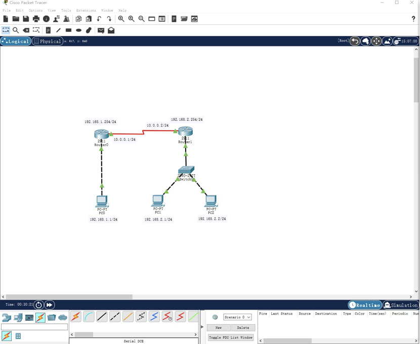
According to the diagram, the connection topology is as follows:
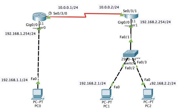
According to the above figure, connect the router with each host. The name of router Router1 is changed to your initials. Please your topology diagram:
1.1 configure the name of the router as R0, set the privileged password and telnet login password
Configure command and response messages
Router>en
Router#conf t
Enter configuration commands, one per line. End with CNTL/Z.
Router(config)#hostname R0
R0(config)#enable password 123456
R0(config)#line vty 0 4
R0(config-line)#password 123456
R0(config-line)#login
R0(config-line)#exit
1.2 configure the ip address of port g0/0 and open the port
Configure Loopback address as 1.1.1.1/32
R0(config)#int loopback 0

R0(config-if)#
%LINK-5-CHANGED: Interface Loopback0, changed state to up

%LINEPROTO-5-UPDOWN: Line protocol on Interface Loopback0, changed state to up

R0(config-if)#ip address 1.1.1.1 255.255.255.255
R0(config-if)#no shutdown
R0(config-if)#exit
R0(config)#int g0/0
R0(config-if)#ip address 192.168.1.254 255.255.255.0
R0(config-if)#no shutdown

R0(config-if)#
%LINK-5-CHANGED: Interface GigabitEthernet0/0, changed state to up

%LINEPROTO-5-UPDOWN: Line protocol on Interface GigabitEthernet0/0, changed state to up

R0(config-if)#
R0#
%SYS-5-CONFIG_I: Configured from console by console
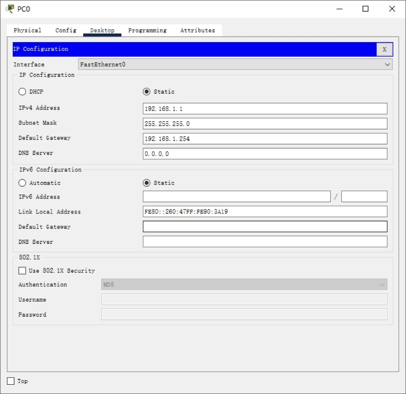
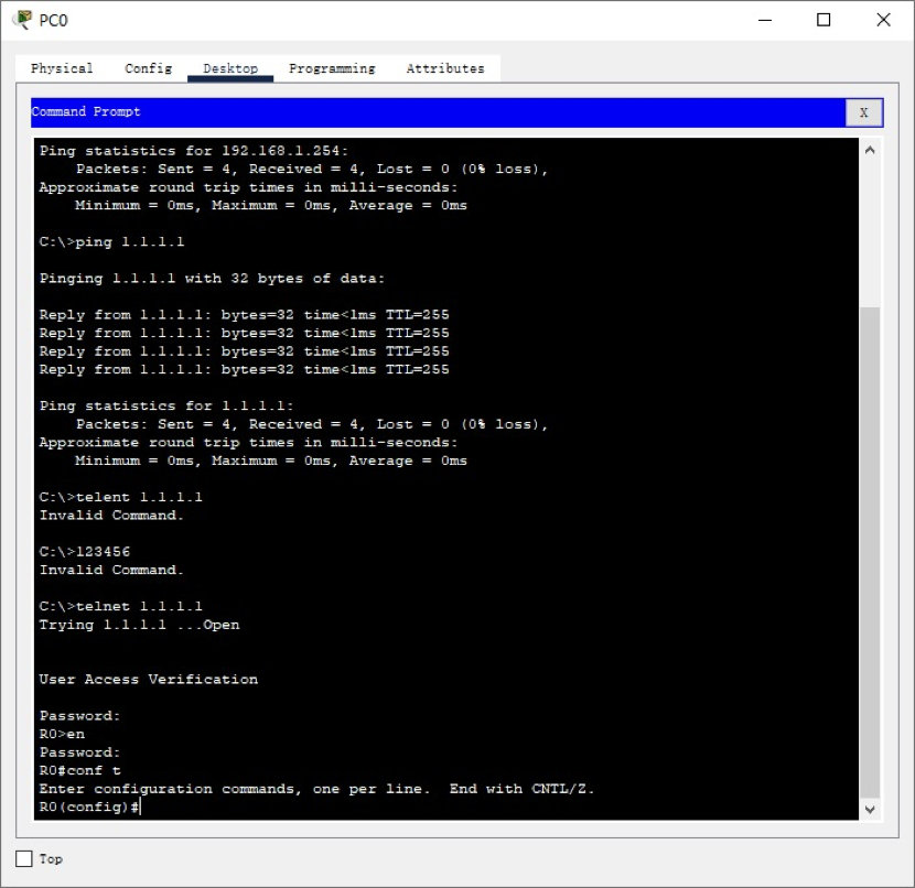
1.3 connect the complete topology, configure the IP address, mask and gateway of PC0, log in to the Loopback address 1.1.1.1 of R0 by telnet, and configure the IP address of serial port s0/3/0 as 10.0.0.1/24 The screenshot is as follows:
1.4 configure router Router1. The router name is your initials, and configure ports S0/3/1 and G0/0
Configure command and response messages
Router>en
Router#conf t
Enter configuration commands, one per line. End with CNTL/Z.
Router(config)#int s0/3/1
Router(config-if)#ip address 10.0.0.2 255.255.255.0
Router(config-if)#no shutdown

Router(config-if)#
%LINK-5-CHANGED: Interface Serial0/3/1, changed state to up

%LINEPROTO-5-UPDOWN: Line protocol on Interface Serial0/3/1, changed state to up

Router(config-if)#exit
Router(config)#hostname SHX
SHX(config)#
SHX(config)#int g0/0
SHX(config-if)#ip address 192.168.2.254 255.255.255.0
SHX(config-if)#no shutdown

SHX(config-if)#
%LINK-5-CHANGED: Interface GigabitEthernet0/0, changed state to up

%LINEPROTO-5-UPDOWN: Line protocol on Interface GigabitEthernet0/0, changed state to up
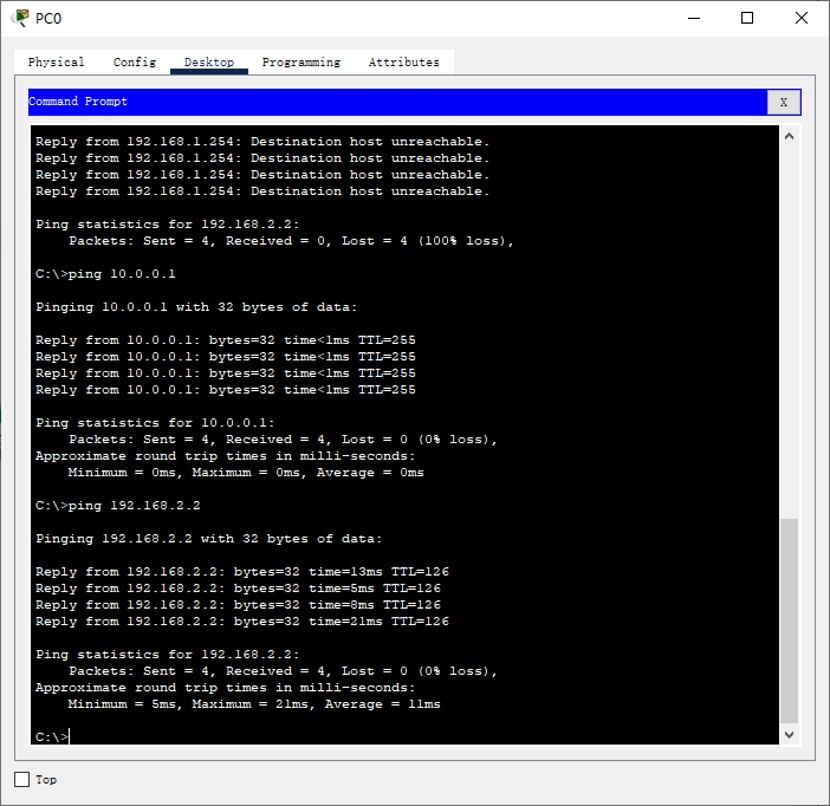
1.5. Check the communication between hosts:
PC0 - > PC2, the screenshot is as follows:
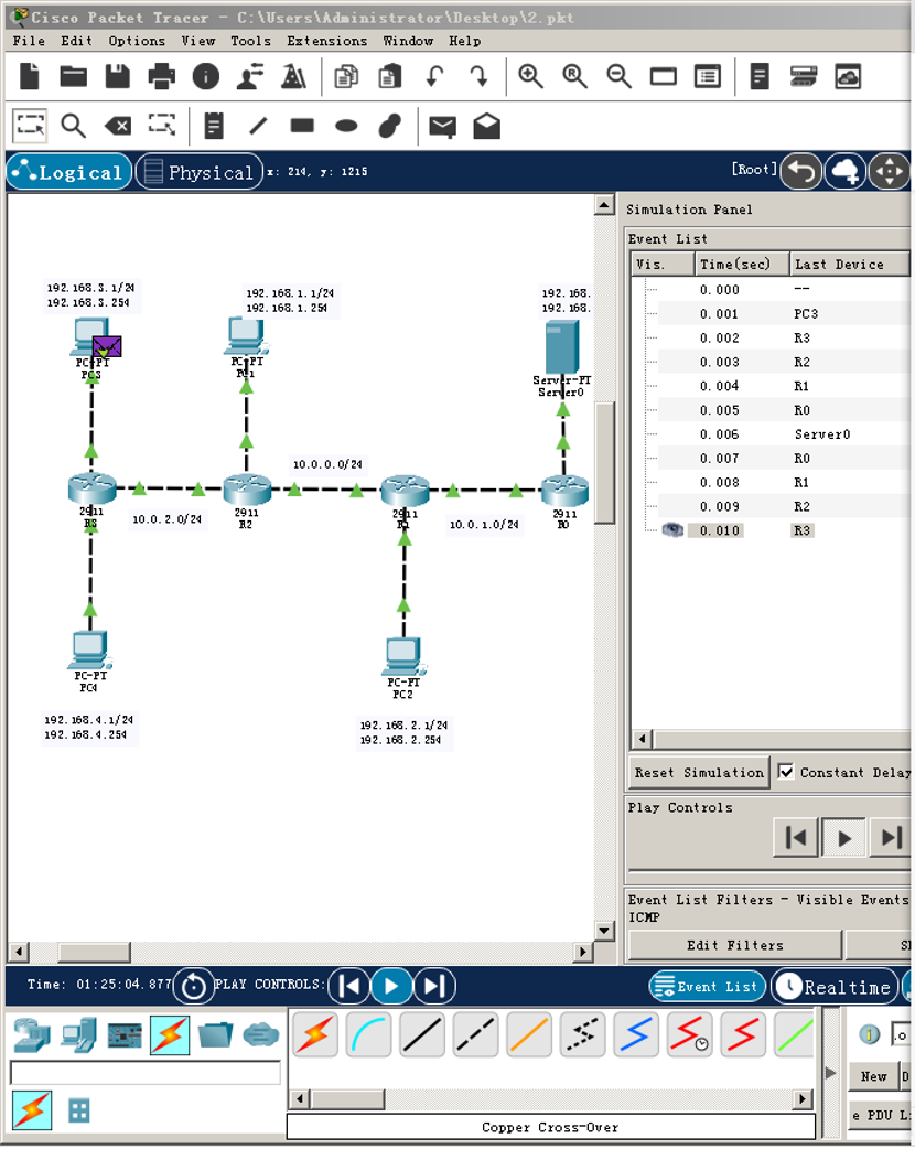
2 experimental configuration II
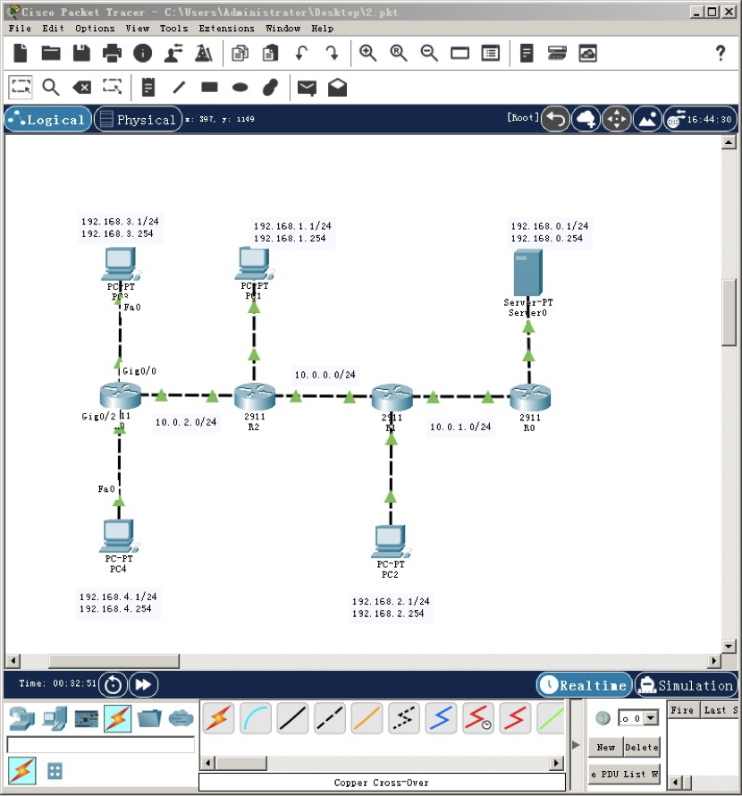
(please note the difference between the router and host numbers in the topology of the experimental job and the topology on the example video)
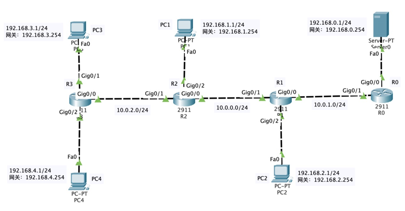
According to the above figure, connect the router and each host through the Gigabit Ethernet interface, and mark the name of router Router1 as your initials. Please put your topology map nearby:
2.1 configure the router name and the IP address of each interface
Basic interface configuration of R0
Router>en
Router#conf t
Enter configuration commands, one per line. End with CNTL/Z.
Router(config)#hostname R0
R0(config)#int g0/0
R0(config-if)#ip address 192.168.0.254 255.255.255.0
R0(config-if)#no shutdown

R0(config-if)#
%LINK-5-CHANGED: Interface GigabitEthernet0/0, changed state to up

%LINEPROTO-5-UPDOWN: Line protocol on Interface GigabitEthernet0/0, changed state to up

R0(config-if)#int g0/1
R0(config-if)#ip address 10.0.1.2 255.255.255.0
R0(config-if)#no shutdown

R0(config-if)#
%LINK-5-CHANGED: Interface GigabitEthernet0/1, changed state to up

%LINEPROTO-5-UPDOWN: Line protocol on Interface GigabitEthernet0/1, changed state to up
Basic interface configuration of R1 (the name of router Router1 is modified to your initials)
Router>en
Router#conf t
Enter configuration commands, one per line. End with CNTL/Z.
Router(config)#hostname SHX
SHX(config)#int g0/0
SHX(config-if)#ip address 10.0.1.1 255.255.255.0
SHX(config-if)#no shutdown

SHX(config-if)#
%LINK-5-CHANGED: Interface GigabitEthernet0/0, changed state to up

SHX(config-if)#int g0/1
SHX(config-if)#ip address 10.0.0.2 255.255.255.0
SHX(config-if)#no shutdown

SHX(config-if)#
%LINK-5-CHANGED: Interface GigabitEthernet0/1, changed state to up

%LINEPROTO-5-UPDOWN: Line protocol on Interface GigabitEthernet0/1, changed state to up

SHX(config-if)#int g0/2
SHX(config-if)#ip address 192.168.2.254 255.255.255.0
SHX(config-if)#no shutdown

SHX(config-if)#
%LINK-5-CHANGED: Interface GigabitEthernet0/2, changed state to up

%LINEPROTO-5-UPDOWN: Line protocol on Interface GigabitEthernet0/2, changed state to up
Basic interface configuration of R2
Router>en
Router#conf t
Enter configuration commands, one per line. End with CNTL/Z.
Router(config)#hostname R2
R2(config)#int g0/0
R2(config-if)#ip address 10.0.0.1 255.255.255.0
R2(config-if)#no shutdown

R2(config-if)#
%LINK-5-CHANGED: Interface GigabitEthernet0/0, changed state to up

R2(config-if)#int g0/1
R2(config-if)#ip address 10.0.2.2 255.255.255.0
R2(config-if)#no shutdown

R2(config-if)#
%LINK-5-CHANGED: Interface GigabitEthernet0/1, changed state to up

%LINEPROTO-5-UPDOWN: Line protocol on Interface GigabitEthernet0/1, changed state to up

R2(config-if)#int g0/2
R2(config-if)#ip address 192.168.1.254 255.255.255.0
R2(config-if)#no shutdown

R2(config-if)#
%LINK-5-CHANGED: Interface GigabitEthernet0/2, changed state to up

%LINEPROTO-5-UPDOWN: Line protocol on Interface GigabitEthernet0/2, changed state to ups
Basic interface configuration of R3
R3>en
R3#conf t
Enter configuration commands, one per line. End with CNTL/Z.
R3(config)#int gi
R3(config)#int gigabitEthernet 0/1
R3(config-if)#ip address 10.0.2.1 255.255.255.0
Bad mask /24 for address 10.0.2.0
R3(config-if)#no shutdown

R3(config-if)#
%LINK-5-CHANGED: Interface GigabitEthernet0/2, changed state to up

%LINEPROTO-5-UPDOWN: Line protocol on Interface GigabitEthernet0/2, changed state to up

R3(config-if)#int gigabitEthernet 0/0
R3(config-if)#ip address 192.168.3.254 255.255.255.0
R3(config-if)#no shutdown

R3(config-if)#
%LINK-5-CHANGED: Interface GigabitEthernet0/0, changed state to up

%LINEPROTO-5-UPDOWN: Line protocol on Interface GigabitEthernet0/0, changed state to up

R3(config-if)#int gigabitEthernet 0/2
R3(config-if)#ip address 192.168.4.254 255.255.255.0
R3(config-if)#no shutdown

R3(config-if)#
%LINK-5-CHANGED: Interface GigabitEthernet0/2, changed state to up

%LINEPROTO-5-UPDOWN: Line protocol on Interface GigabitEthernet0/2, changed state to up
2.2 configure the host address, subnet mask and gateway
| IP address | Subnet mask | Default gateway | Connected router | Port number | |
|---|---|---|---|---|---|
| PC0 | 192.168.1.1 | 255.255.255.0 | 192.168.1.254 | R2 | G0/2 |
| PC1 | 192.168.2.1 | 255.255.255.0 | 192.168.2.254 | R1 | G0/2 |
| PC2 | 192.168.3.1 | 255.255.255.0 | 192.168.3.254 | R3 | G0/0 |
| PC3 | 192.168.4.1 | 255.255.255.0 | 192.168.4.254 | R3 | G0/2 |
| SERVER | 192.168.0.1 | 255.255.255.0 | 192.168.0.254 | R0 | G0/0 |
2.3 view the routing information of each router
View the routing information, commands and feedback of router R0
R0#show ip route
Codes: L - local, C - connected, S - static, R - RIP, M - mobile, B - BGP
D - EIGRP, EX - EIGRP external, O - OSPF, IA - OSPF inter area
N1 - OSPF NSSA external type 1, N2 - OSPF NSSA external type 2
E1 - OSPF external type 1, E2 - OSPF external type 2, E - EGP
i - IS-IS, L1 - IS-IS level-1, L2 - IS-IS level-2, ia - IS-IS inter area
* - candidate default, U - per-user static route, o - ODR
P - periodic downloaded static route

Gateway of last resort is not set

10.0.0.0/8 is variably subnetted, 2 subnets, 2 masks
C 10.0.1.0/24 is directly connected, GigabitEthernet0/1
L 10.0.1.2/32 is directly connected, GigabitEthernet0/1
192.168.0.0/24 is variably subnetted, 2 subnets, 2 masks
C 192.168.0.0/24 is directly connected, GigabitEthernet0/0
L 192.168.0.254/32 is directly connected, GigabitEthernet0/0
Direct network number information of each router
| Router | R0 | R1 | R2 | R3 |
|---|---|---|---|---|
| Direct network number | 192.168.0.0/24 10.0.1.0/24 | 192.168.2.0/24 10.0.0.0/24 10.0.1.0/24 | 192.168.1.0/24 10.0.2.0/24 10.0.0.0/24 | 192.168.3.0/24 192.168.4.0/24 10.0.2.0/24 |
2.4 static routing table items to be configured for each router
| Router | R0 | R1 | R2 | R3 |
|---|---|---|---|---|
| network number | 192.168.3.0/24 192.168.4.0/24 192.168.1.0/24 192.168.2.0/24 10.0.2.0/24 10.0.0.0/24 | 192.168.3.0/24 192.168.4.0/24 192.168.1.0/24 192.168.0.0/24 10.0.2.0/24 | 192.168.3.0/24 192.168.4.0/24 10.0.1.0/24 192.168.2.0/24 192.168.0.0/24 | 10.0.0.0/24 10.0.1.0/24 192.168.1.0/24 192.168.2.0/24 192.168.0.0/24 |
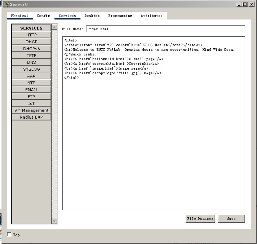
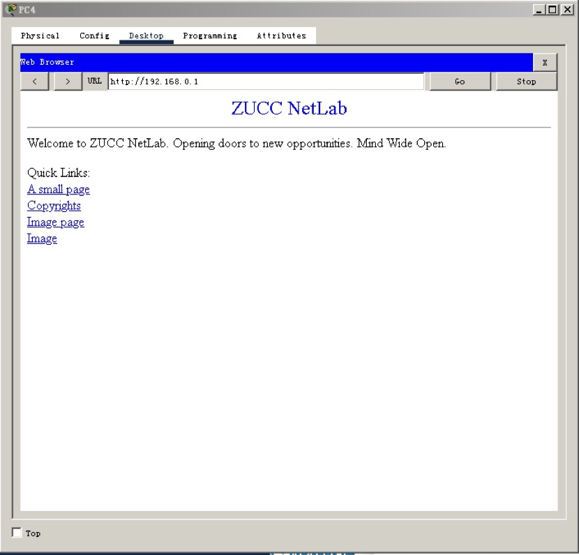
2.5 configure HTTP server and modify index HTML, add ZUCC NetLab and other information, and the screenshot is as follows:
2.6 verify connectivity
Add a simple PDU between PC3 and HTTP Server for verification. The screenshot is as follows:
Use the Web browser of PC4 to access the page of HTTP server. The screenshot is as follows:
4, Harvest feeling:
Through this experiment, I understand the basic configuration method of static routing and the role of routing table, and deepen my understanding of the role of router, which will benefit me a lot in the future theoretical courses.