preface
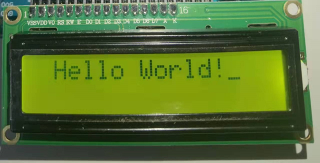
Display unit is the most important output device in embedded engineering and electronic products. 16x2 LCD is one of the most commonly used display units. 1602 LCD indicates that there are two lines, each line can display 16 characters, and each character occupies 5X7 matrix space on the LCD.
In this paper, we connect 1602 LCD module to AT89S52 MCU. AT89S52 MCU access to LCD may seem quite complex for novices, but after understanding this concept, it becomes very simple. This process takes some time, because you need to understand the 16 pins of LCD and connect them to MCU.
Understanding 1602 LCD
1602 pin description
Let's first understand the 16 pins of the LCD module.
We can divide them into five categories: power pin, comparison pin, control pin, data pin and backlight pin.
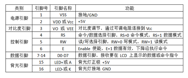
Except for the control pin, the name and function of all pins are clear at a glance. It is necessary to make some instructions for the control pin:
Rs: RS is the register selection pin. If we want to send some data to be displayed on the LCD, we need to set it to 1. If we set some commands to hexadecimal (e.g. 01), we will clear the screen.
RW: This is the read / write pin. If we want to write some data on the LCD, we set it to 0. If we read from the LCD module, set it to 1. It is generally set to 0 because we don't need to read data from LCD.
E: Enable control is essentially equivalent to the clock pin. Write data and command to LCD. After sending the data or command to the data line, the e pin receives a falling edge before sending the data and command to 1602.
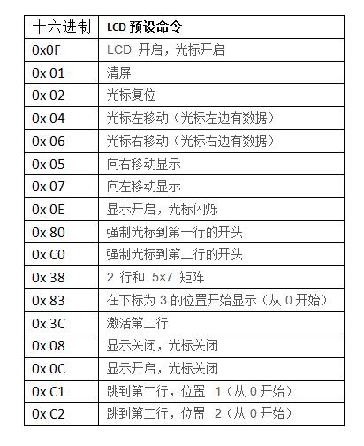
1602 preset command
There are some preset commands in 1602 LCD # and we use them in the following program to prepare LCD (in lcd_init() function). Some important command descriptions are given below:
Test circuit diagram and description
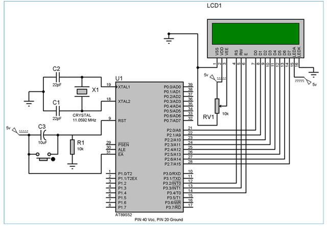
The circuit diagram of the interface between LCD and 8051 single chip microcomputer is shown in the above figure.
We connect the data pin (D0-D7) of LCD to port 2 (P2_0 – P2_7) of MCU. The control pins RS, RW and E are respectively connected to pins 12, 13 and 14 of the MCU (pins 2, 3 and 4 of port 3).
PIN 2 (VDD) and PIN 15 (backlight power supply) of LCD are connected to power supply (5v), PIN 1 (VSS) and PIN 16 (backlight ground) are grounded.
PIN 3 (VEE) is connected to the voltage (Vcc) through a 10k variable resistor to adjust the contrast of the LCD. The middle pin of the variable resistor is connected to PIN 3, and the other two legs are connected to power supply and ground respectively.
Test procedure
As described above about command mode and data mode, you can see:
When sending a command (function lcd_cmd), set to
RS=0 (RS=0 command mode, RS=1 data mode)
RW=0 (RW=0 write mode, RW=1 read mode),
And by setting e to 1 and then 0, the high to low pulse (falling edge) is supplied to E
In addition, when sending data (function lcd_data) to LCD, it is set to
RS=1,RW=0
And high to low pulses (falling edge) are supplied to E by setting E to 1 to 0.
The delay function msdelay() delays in milliseconds and is frequently called in the program. The delay function is called to give the LCD module enough time to execute internal operations and commands.
while loop print string, calling LCD every time_ Data function to print a character until the last character (null Terminator - '\ 0').
lcd_ The init() function initializes the LCD with preset commands, as described above.
//1602 LCD and 8051 microcontroller (AT89S52) interface program

#include<reg51.h>

#define display_port P2 / / the data pin is connected to port 2 on the microcontroller

sbit rs = P3^2; //The RS # pin is connected to pin # 2 of port # 3

sbit rw = P3^3; // The RW # pin is connected to pin # 3 of port # 3

sbit e = P3^4; //The E pin is connected to pin 4 of port 3

void msdelay(unsigned int time) //Delay function in milliseconds.

{
    unsigned i,j ;
    for(i=0;i<time;i++)
    for(j=0;j<1275;j++);
}

void lcd_cmd(unsigned char command) //Function to send command to LCD
{
    display_port = command;
    rs = 0;
    rw=0;
    e=1;
    msdelay(1);
    e=0;
}

void lcd_data(unsigned char disp_data) //Function to send display data to LCD
{
    display_port = disp_data;
    rs = 1;
    rw=0;
    e=1;
    msdelay(1);
    e=0;
}

void lcd_init() //Initialize LCD
{

    lcd_cmd(0x38); //LCD for use with # 2 # rows and # 5X7 # matrix

    msdelay(10);

    lcd_cmd(0x0F); //When the display is turned on, the cursor flashes

    msdelay(10);
    lcd_cmd(0x01); //Clear screen
    msdelay(10);
    lcd_cmd(0x81); //Move the cursor to line # 1 # 1
    msdelay(10);
}

void main()
{
    unsigned char a[15]="Hello World!"; // A 14 # character string with a null terminator.
    int i=0;
    lcd_init();
    while(a[i] != '\0') //Until the null terminator in the string
    {
        lcd_data(a[i]);
        i++;
        msdelay(50);
    }

    while(1);

}